Technical Specifications and Product IDs

This appendix lists specifications for the following routers:

Cisco ASR 9000v Satellite Shelf

This section contains product names, product IDs, and hardware specifications for the Cisco ASR 9000v satellite shelf.

Cisco ASR 9000v Satellite Shelf Product IDs

Table 1. Cisco ASR 9000v Satellite Shelf System Product IDs

Product ID

Description

ASR-9000v-AC

44-Port GE + 4-Port 10-GE ASR 9000v, AC Power

ASR-9000v-24-A

44-Port GE + 4-Port 10-GE ASR 9000v, +24 V DC Power ANSI Chassis

ASR-9000v-DC-A

44-Port GE + 4-Port 10-GE ASR 9000v, DC Power ANSI Chassis

ASR-9000v-DC-E

44-Port GE + 4-Port 10-GE ASR 9000v, DC Power ETSI Chassis

A9KV-V2-AC

44-Port GE + 4-Port 10-GE ASR 9000v Version 2, AC Power

A9KV-V2-DC-A

44-Port GE + 4-Port 10-GE ASR 9000v Version 2, DC Power ANSI Chassis

A9KV-V2-DC-E

44-Port GE + 4-Port 10-GE ASR 9000v Version 2, DC Power ETSI Chassis

A9K-NVSAT1-LIC(=)

ASR-9000 nV Host License for up to 1 nV Clients

A9K-NVSAT5-LIC(=)

ASR-9000 nV Host License for up to 5 nV Clients

A9K-NVSAT20-LIC(=)

ASR-9000 nV Host License for up to 20 nV Clients

ASR-9000v-FAN

ASR-9000v Fan Tray with Filter

A9KV-V2-FAN

ASR-9000v Version 2 Fan Tray with Filter

Cisco ASR 9000v Satellite Shelf System Specifications

This section provides the specifications for timing, power, and environmental specifications, and shelf dimensions of the Cisco ASR 9000v satellite shelf system.

The GPS (Global Positioning System) interface (1-PPS and 10-MHz) specifications are listed in this table.

Table 2. GPS (Global Positioning System) Interface (1PPS and 10MHz) of the Cisco ASR 9000v Satellite Shelf System

10-MHz Specification

1-PPS Specification

Waveform

Sine wave

Pulse

Frequency

10 MHz

1 PPS

Amplitude

> 1 V LVTTL Compatible

> 1 V LVTTL Compatible

Impedance

50 Ohms

50 Ohms

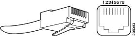
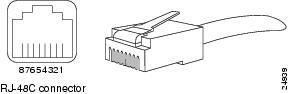
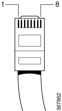
The pinout of the TOD (Time of Day) RJ-45 port is listed in the tale below.

Table 3. TOD/1PPS RS422 Interface— RJ-45 Pinout of the Cisco ASR 9000v Satellite Shelf System

Pin

Signal Name

Description

1

1PPS_N

1PPS RS422 output signal

2

1PPS_P

1PPS RS422 output signal

3

NC

No Connect

4

GND

5

GND

6

NC

No Connect

7

TOD_P

Time of Day RS422 output

8

TOD_N

Time of Day RS422 output

System Power for the Cisco ASR 9000v Satellite Shelf

Cisco ASR 9000v Fan Tray

Table 4. Cisco ASR 9000v Satellite Shelf Fan Tray Power Specifications

Shelf

Input Voltage

Power Consumption

Power Terminals

Fuse Rating

Cisco ASR 9000v satellite shelf with AC power module for ANSI and ETSI standards

100V to 240V AC depending on the standards in various countries; 50/60 Hz nominal (range: 47 to 63 Hz)

100 VAC 2.4 A; 240 VAC 1A

One AC single phase with 3- pole (line L, Neutral N, and Protective Earth PE) input connector.

Must not exceed 10 A or 15 A, depending on the standards in various countries.

Cisco ASR 9000v satellite shelf with 24V DC power module for ANSI standard

Voltages –20 VDC and –28.3 VDC are, respectively, the minimum and maximum voltages required to power the chassis. The nominal steady state voltage is –24 VDC.

24 VDC 10A

Single terminal block with four poles— –24V and RET for power terminals A and B.

Must not exceed 15 A.

Cisco ASR 9000v satellite shelf with 48 V DC power module for ANSI standard

Voltages –40.5 VDC and –57.6 VDC are, respectively, the minimum and maximum voltages required to power the chassis. The nominal steady state voltage is –48 VDC. Functionality is guaranteed at –40 VDC input voltage, according to GR-1089, Issue 5.

48 VDC 5 A

Single terminal block with four poles— –48V and RET for power terminals A and B.

Must not exceed 10 A.

Cisco ASR 9000v satellite shelf with 48 V DC power module for ETSI standard

Voltages –40.5 VDC and –57.6 VDC are, respectively, the minimum and maximum voltages required to power the chassis. The nominal steady state voltage is –48 VDC.

48 VDC 5 A

DSUB 2 poles.

Must not exceed 10 A.

Table 5. Fan Tray Power Requirements

Fan Tray

Watts

Amps

12 V supplied by the Cisco ASR 9000v satellite shelf

36

3

Cisco ASR 9000v Satellite Shelf Physical Dimensions

Table 6. Physical Dimensions of the Cisco ASR 9000v Satellite Shelf System

Shelf

Physical Dimensions

Measurement in inches

Measurement in mm

Height

Width

Depth

Weight in Kg

Height

Width

Depth

Weight in Kg

Cisco ASR 9000v Satellite Shelf

1.7

19 or 23 with mounting ears attached for ANSI rack configuration

21 with mounting ears attached for ETSI rack configuration

9.1

With AC power module: 4.06 kg

With DC power module: 4.22 kg

43.1

482.6 or 584.2 with mounting ears attached for ANSI rack configuration

533.4 mm with mounting ears attached for ETSI rack configuration

231.1

With AC power module: 4.06 kg

With DC power module: 4.22 kg

Cisco ASR 9000v Satellite Shelf Operating Temperature and Humidity

  • Operating Temperature: –5 to 55 degrees Celsius for AC power supply; –40 to 65 degrees Celsius for DC power supply.

  • Operating Humidity: 5 to 85 percent, noncondensing; functionality is guaranteed up to 5 to 95 percent, noncondensing.

Cisco ASR 9000v Satellite Shelf Switching Capacity

Table 7. Switching Capacity of the Cisco ASR 9000v Satellite Shelf System

Shelf

Interface

Switching Capacity

Cisco ASR 9000v Satellite Shelf

44 GE 10/100/1000 Mbps SFP ports

44 GB

4 10-GE SFP+ ports

Cisco ASR 901 as a Satellite Shelf

This section contains hardware specifications for the Cisco ASR 901 as a satellite shelf.

Cisco ASR 901 System Specifications

Table 8. Cisco ASR 901 Router System Specifications

Description

Specification

Dimensions (H x W x D)

1.7 x 17.4 x 8.25 in. (4.37 x 44.2 x 21.0 cm) 1 RU (rack unit) in a 19-in (48.3-cm) rack

Weight

7 lb (3.1 kg)

Console and Auxiliary Ports

RJ-45 connector

Operating Temperature

Operating temperature range is –40 to +65°C (–40 to 149°F)

Non-Operational Temperature

Temperature: –40 to 70 °C (–40 to 21.1°F)

Operating Humidity

10 to 90% RH (non-condensing)

Non-Operational Humidity

Up to 93% RH

Operating Altitude

13,800 ft (4206 m)

Operating Vibration

0.15 G, 10 to 500 Hz/100 minutes per axis

Non-Operational Vibration

0.8 G, 10 to 500 Hz/30 minutes per axis

Operating Acoustics

60 dB

Airflow

Side to side

Cisco ASR 901 Power Specifications

This table lists the DC power supply specifications for the Cisco ASR 901 router.

Table 9. Cisco ASR 901 Router Power Supply Specifications

Specification

Value

DC power supply input voltage

–24/–72 VDC

Maximum input current

3 A

Wire gauge for DC input power connections

16 AWG

Power dissipation

60 W

The Cisco ASR 901 router uses two 3-pin connectors (part number 27-2030-01) for input to the power supply. The terminal block is part of the accessory kit (part number 53-3085-01/53-3295-0), which ships with the Cisco ASR 901 router.

The ground wire connects to a 2-hole lug, which connects to the corresponding mounting point.

With the connector installed in the chassis, the pins numbered from top to bottom are 1, 2, and 3, respectively.

This table lists the pinout configurations for the connector, based on the power source.

Table 10. Power Supply Connector Pinouts (–24/–72 VDC Application)

Pin

Connector A

1

VDC (–24 to –72)

2

RTN

3

Chassis Ground

Pin

Connector B

1

VDC (–24 to –72)

2

RTN

3

Chassis Ground

You can use connector A or B or both.

Cisco ASR 901 Environmental Monitoring Temperature Sensor

The Cisco ASR 901 router has a temperature sensor to detect overtemperature conditions inside the chassis. The overtemperature detection trips at 70°C. This condition is reported to the processor as an interrupt, and the software generates the appropriate alarms. If the router reaches a temperature of 85°C, the power supply cycles itself to prevent the router from exceeding the maximum temperature while being powered up.

Cisco ASR 901 Router Interface Numbering

Each network interface on a Cisco ASR 901 router is identified by a slot number and a port number, explained in this sequence:

  • Logical slot numbers starts from 0 for all built-in interfaces. The numbering format is interface type Slot number/interface number . Interface (port) numbers begin at logical 0 for each interface type.
  • Logical interface numbering for the built-in Ethernet ports runs from g0/0 through g0/3, the combo ports run from g0/4 to g0/7, and the SFP ports run from g0/8 through g0/11. The GE ports are numbered bottom to top, left to right.
Table 11. Cisco ASR 901 Router Interface Labels

Interface

Number

Location

Label

RJ-45 jacks for copper Ethernet ports

8

Onboard

100/1000 ETHERNET

SFP connector for optical GE ports

8

Onboard

Fiber ETHERNET

RJ-45 connector for the console

1

Onboard

CON/AUX

RJ-45 jack for the BITS interface

1

Onboard

BITS

RJ-45 jack for the Time-of-Day interface

1

Onboard

TOD

1-PPS mini-coax timing connector

1

Onboard

1PPS

10-MHz mini-coax timing connector

1

Onboard

10MHZ

Power connector

1

Onboard

Power Connector

Cisco ASR 901 Cable Specifications

If you prefer to build your own cables, this section provides cable specifications for the Cisco ASR 901 router.

Gigabit Ethernet Connector Pinouts

This section illustrates the Gigabit Ethernet RJ-45 connector and lists its pinout and signal descriptions. Note that the RJ-45 ports are capable of operating in both 100BaseT and 1000BaseT modes.

This figure shows the RJ-45 connector and port, and the RJ-45 Connector Pinouts table lists the connector pinouts and signals.

Figure 1. RJ-45 Connector and Port
Table 12. RJ-45 Connector Pinouts

Pin

FE Signal

GE Signal

1

TX data+

TX A+

2

TX data–

TX A–

3

RX data+

RX B+

4

Not used

TX C+

5

Not used

TX C–

6

RX data–

RX B–

7

Not used

RX D+

8

Not used

RX D–

SFP Port Pinouts and Cable Specifications

For information about SFP modules supported by the Cisco ASR 901 router, including pinouts, see the Cisco Interfaces and Modules support section on Cisco.com.


Note


Pins not listed in the tables in this appendix are not connected.

T1/E1 Port Pinouts

This figure shows the RJ-48C connector used by the T1/E1 ports on the TDM interface module on the Cisco ASR 901 router.

Figure 2. RJ-48C Connector

This figure shows the RJ-48C connector wiring for the T1/E1 cable.

Figure 3. RJ-48-to-RJ-48 T1/E1 Cable Wiring

Note


We recommend using a shielded cable for RJ-48C connectors.

This table shows the pinout configuration for the RJ-48C connectors on the Cisco ASR 901 router for both the shielded and unsaddled cables for either T1 or E1. This table shows the pinout configuration for the RJ-45 connectors on the TDM interface module on the Cisco ASR 901 router.

Table 13. T1/E1 Port Pinout for the Cisco ASR 901 Router

Pin

Signal Name

Direction

Description

1

RX Tip

Input

Receive Tip

2

RX Ring

Input

Receive Ring

3

Not Used

4

TX Tip

Output

Transmit Tip

5

TX Ring

Output

Transmit Ring

6

Not Used

7

Not Used

8

Not Used

Console Port Signals and Pinouts

The Cisco ASR 901 router ships with a console cable kit, which contains the cable and adapters to connect a console terminal (an ASCII terminal or PC running terminal emulation software). The console cable kit includes the following items:

  • RJ-45-to-RJ-45 rollover cable

  • RJ-45-to-DB-9 female DTE adapter (labeled TERMINAL)

  • RJ-45-to-DB-25 female DTE adapter (labeled TERMINAL)

To connect a modem, you need to order an auxiliary cable.

Use the thin, flat, RJ-45-to-RJ-45 rollover cable and the RJ-45-to-DB-9 female DTE adapter (labeled TERMINAL) to connect the console port to a PC running terminal emulation software. This figure shows how to connect the console port to a PC. The Console Port Pinouts table lists the pinouts for the asynchronous serial console port, the RJ-45-to-RJ-45 rollover cable, and the RJ-45-to-DB-9 female DTE adapter (labeled TERMINAL).

Figure 4. Connecting the Console Port to a PC

This table lists the Console port pinouts for the Cisco ASR 901 router.

Table 14. Console Port Pinouts

Pin

Signal Name

HP Pins

Direction

Description

1

RTS

UART_RTS1

Output

Request to send

2

DTR

NC

3

TXD

UART_SOUT1

Output

Transmit data

4

RI

GND

Ring indicator

5

GND

GND

6

RXD

UART_SIN1

Input

Receive data

7

DSR/DCD

NC

Input

Data set ready/data carrier detect

8

CTS

UART_CTS1

Input

Clear to send

This table describes the pinouts RJ-45-to-RJ-45 and RJ-45-to-DB-9 rollover cables.

Table 15. Console Port Signaling and Cabling Using a DB-9 Adapter

Console

Port (DTE)

RJ-45-to-RJ-45 Rollover Cable

RJ-45-to-DB-9

Terminal Adapter

(Connected to

Rollover Cable)

Console

Device

Signal

RJ-45 Pin

RJ-45 Pin

DB-9 Pin

Signal

RTS

11

8

8

CTS

DTR

2

7

6

DSR/DCD

TxD

3

6

2

RxD

GND/RI

4

5

5

GND

GND

5

4

5

GND/RI

RxD

6

3

3

TxD

DSR/DCD

7

2

4

DTR

CTS

81

1

7

RTS

1 Pin 1 is connected internally to pin 8.

This table lists the pinouts for the asynchronous serial console port, the RJ-45-to-RJ-45 rollover cable, and the RJ-45-to-DB-25 female DTE adapter (labeled TERMINAL).

Table 16. Console Port Signaling and Cabling Using a DB-25 Adapter

Console

Port (DTE)2

RJ-45-to-RJ-45 Rollover Cable

RJ-45-to-DB-25

Terminal Adapter

Console

Device

Signal

RJ-45 Pin

RJ-45 Pin

DB-25 Pin

Signal

RTS

13

8

5

CTS

DTR

2

7

6

DSR/DCD

TxD

3

6

3

RxD

GND/RI

4

5

7

GND

GND

5

4

7

GND/RI

RxD

6

3

2

TxD

DSR/DCD

7

2

20

DTR

CTS

82

1

4

RTS

2 You can use the same cabling to connect a console to the auxiliary port.
3 Pin 1 is connected internally to pin 8.

BITS Port Pinouts

This table list the pinouts for the BITS interface RJ-45 port on the Cisco ASR 901 router.

Table 17. BITS Pinouts for the Cisco ASR 901 Router

Pin

Signal Name

Direction

Description

1

RX ring

Input

Receive ring

2

RX tip

Input

Receive tip (T1/E1)

3

Not connected

4

TX ring

Output

Transmit ring

5

TX tip

Output/input

Transmit tip (T1/E1)

6

Not connected

7

Not connected

8

Not connected

Time of Day Pinouts

This table lists the pinouts for the Time of Day RJ-45 interface on the Cisco ASR 901 router.

Table 18. Time of Day RJ-45 Interface Pinout

Pin

Signal Name

Direction

Description

1

Not connected

2

Not connected

3

Not connected

4

Ground

5

Ground

6

Not connected

7

TOD_N

Output/Input

Time of Day RS422 differential input or output

8

TOD_P

Output/Input

Time of Day RS422 differential input or output

GPS Port Pinouts

The Cisco ASR 901 router has a 10-MHz and a 1-PPS GPS port that allow you to configure input or output clocking with a GPS device. This table summarizes the pinouts for the 10-MHz and 1-PPS interfaces.


Note


For pinouts related to ToD and 1 PPS using the BITS interface, see #con_1017835.
Table 19. GPS Port Pinouts for the Cisco ASR 901 Router

10 MHz

1 PPS

Waveform

Input: Sine wave

Output: Square wave

Input: Pulse shape

Output: Pulse shape

Amplitude

Input: > 1.7 volt p-p(+8 to +10 dBm)

Output: > 2.4 volts TTL compatible

Input: > 2.4 volts TTL compatible

Output: > 2.4 volts TTL compatible

Impedance

50 ohms

50 ohms

Pulse Width

50% duty cycle

26 microseconds

Rise Time

Input: AC coupled

Output: 5 nanoseconds

40 nanoseconds

The 1-PPS interface type is Series 1.0 / 2.3, 50 ohms.

For instructions on how to configure the 10-MHz and 1-PPS ports, see the http://www.cisco.com/c/en/us/td/docs/wireless/asr_901/Configuration/Guide/b_asr901-scg/b_asr901-scg_preface_00.html Cisco ASR 901 Router Mobile Wireless Software Configuration Guide .

Alarm Port Pinouts

This table lists the pinouts for the alarm port (RJ-45) on the Cisco ASR 901 router.

Table 20. Alarm Port Pinout

Pin

Signal Name

Description

1

Alarm input 1

2

Alarm input 2

3

Not connected

4

Alarm input 3

5

Alarm input 4

6

Not connected

7

Not connected

8

Not connected

Management Ethernet Port Pinouts

This table lists the pinouts for the management Ethernet port (RJ-45) on the Cisco ASR 901 router.

Table 21. Management Ethernet Pinout

Pin

Signal Name

1

RxD_P

2

RxD_N

3

TxD_P

4

Not connected

5

Not connected

6

TxD_N

7

Not connected

8

Not connected

Cisco ASR 903 as a Satellite Shelf

Cisco ASR 903 System Specifications

This table summarizes the system specifications and environmental requirements for the Cisco ASR 901.

Table 22. Cisco ASR 901 System Specifications

Dimensions (Height x Width x Depth)

5.22 x17.44 x 10.565 in. (132.588 x 442.976 x 268.351 mm)

Note

 
This measurement includes handles from the power supply, fan tray, and interface modules installed in the chassis.

Weight

27.117 lb (12.3 kg)

Note

 
This weight includes a redundant RSP and power supply.

Operating Temperature

The Cisco ASR 901 supports the following temperature ranges with the DC power supply:

  • –60 to 4000 meters: –40 to 104ºF(–40 to 40ºC)

  • –60 to 1800 meters: –40 to 149ºF(–40 to 65ºC)

The Cisco ASR 901 supports the following temperature ranges with the AC power supply:

  • –60 to 4000 meters: 32 to 104ºF (0 to 40ºC)

  • –60 to 1800 meters: 23 to 140ºF(–5 to 60ºC)

Nonoperating Temperature

–40ºF to 185ºF (–40ºC to +85ºC) storage temperature

Operating Humidity

5 to 95% operating noncondensing relative humidity

Operating Altitude

–60-m to 1800-m operating altitude for full operating temperature range; up to 4000 m at up to 40ºC.

Nonoperating Altitude

4572-m storage altitude

Vibration

1.0 G from 1.0 to 150 Hz

Shock

30 G half sine 6 ms and 11 ms

Nonoperating Vibration

Random: 1.15 gRMS 3 to 200 Hz, 30 minutes/axis

Sine: 10 to 500 Hz @ 0.8 G peak / 5 sweep cycles/axis

Operating Acoustics

Less than 55 dBa @ 27ºC

ASR 903 Connector and Cable Specifications

The following sections describe the pinouts for the Cisco ASR 903 Router satellite shelf interfaces:

Alarm Port Pinout

Table 23. External Alarm Input Pinout

Pin

Signal Name

Description

1

ALARM0_IN

Alarm input 0

2

ALARM1_IN

Alarm input 1

3

Not connected

4

ALARM2_IN

Alarm input 2

5

ALARM3_IN

Alarm input 3

6

Not connected

7

Not connected

8

COMMON

Alarm common

Console/Aux RJ-45 RS-232 Serial Port Pinout

Table 24. Console/Aux RJ-45 RS-232 Serial Port

Pin

Signal Name

Direction

Description

1

RTS

Output

Request to send

2

DTR

Output

Data terminal ready (always on).

3

TXD

Output

Transmit data

4

RI

Ring indicator

5

GND

6

RXD

Input

Receive data

7

DSR/DCD

Input

Data set ready/data carrier detect

8

CTS

Input

Clear to send

Management Ethernet Port Pinout

Table 25. Management Ethernet Port Pinout

Pin

Signal Name

1

TRP0+

2

TRP0-

3

TRP1+

4

TRP2+

5

TRP2-

6

TRP1-

7

TRP3+

8

TRP3-

USB Console Port Pinout

Table 26. Single USB Console Port

Pin

Signal Name

Description

A1

Vcc

+5 VDC (500 mA)

A2

D-

Data -

A3

D+

Data +

A4

Gnd

Ground


Note


The USB console port +5 VDC is input and operates as an USB peripheral device.

USB Flash/MEM Port Pinout

Table 27. Single USB Flash/MEM Port

Pin

Signal Name

Description

A1

Vcc

+5VDC (500mA)

A2

D–

Data –

A3

D+

Data +

A4

Gnd

Ground


Note


A USB TYPE-A receptacle is used.

Note


The USB flash/MEM port +5 VDC is output. We provide power for USB flash/MEM, and it operates as a USB host device.

Fiber-Optic Specifications

The specification for optical fiber transmission defines two types of fiber: single-mode and multimode. Within the single-mode category, three transmission types are defined: short reach, intermediate reach, and long reach. Within the multimode category, only short reach is available. For information about optical SFP modules, see the documentation for the SFP module at:

https://www.cisco.com/c/en/us/support/interfaces-modules/transceiver-modules/products-installation-guides-list.html