Overview

The Cisco ASR 9000v, Cisco ASR 901 Mobile Wireless Router, and Cisco ASR 903 Router are supported as satellite systems with the Cisco ASR 9000 Series, as described in this table.

Table 1. Routers Supported as Satellite Systems with the Cisco ASR 9000 Series

Cisco IOS XR Release

Description

5.2.2

Introduced support for the Cisco ASR 9000v version 2 satellite shelf with the Cisco ASR 9000 Series.

4.3.2

Introduced support for the Cisco ASR 9000v satellite shelf with the Cisco CRS Line Card Chassis in the following systems:

  • Cisco CRS 8-slot Line Card Chassis in a back-to-back system

  • Cisco CRS 16-slot Line Card Chassis in a back-to-back system

  • Cisco CRS 16-slot Line Card Chassis in a multishelf system

4.3.1

Introduced support for the Cisco ASR 9000v satellite shelf with the Cisco CRS Line Card Chassis (in the 8-slot or 16-slot variation).

4.3.0

Introduced support for the Cisco ASR 901 Mobile Wireless Router and the Cisco ASR 903 Router as satellite systems with the Cisco ASR 9000 Series.

4.2.1

Introduced the Cisco ASR 9000v as a satellite system with the Cisco ASR 9000 Series.


Note

Throughout this document, the generic term Cisco ASR 9000v satellite shelf refers to the Cisco ASR 9000v satellite shelf (ASR-9000V-AC, ASR-9000V-DC-A, ASR-9000v-24-A, and ASR-9000V-DC-E) and the Cisco ASR 9000v version 2 satellite shelf (A9KV-V2-DC-A and A9KV-V2-DC-E), unless otherwise specified.

For more information on the Cisco ASR 9000 Series, see the Cisco ASR 9000 Series Aggregation Services Router Hardware Installation Guide and the Cisco ASR 9000 Series Aggregation Services Router Overview and Reference Guide.

For more information on the Cisco CRS Line Card Chassis, see the http://www.cisco.com/c/en/us/support/routers/carrier-routing-system/products-installation-guides-list.html Cisco CRS Carrier Routing System Installation Guides.

For Cisco IOS XR software Ethernet port configuration and command information, see the Cisco ASR 9000 Series Aggregation Services Router Interface and Hardware Component Command Reference and the Cisco ASR 9000 Series Aggregation Services Router Interface and Hardware Component Configuration Guide .

For information specific to Cisco IOS XR software, see the Release Notes for Cisco ASR 9000 Series Aggregation Services Routers for Cisco IOS XR Software .

Power Supply Safety Precautions

Observe the following general safety precautions and recommendations in planning the source power requirements for the Cisco ASR 9000v, Cisco ASR 901, and Cisco ASR 903 routers:

  • Check the power at your site before router installation (and periodically after installation) to ensure that clean power (free of spikes and noise) is being received.
  • Always disconnect the power source and unplug the power cable before working on the router.
  • Install proper grounding for the site to avoid damage from lightning and power surges.

Warning

To avoid electric shock, do not connect safety extra-low voltage (SELV) circuits to telephone-network voltage (TNV) circuits. LAN ports contain SELV circuits, and WAN ports contain TNV circuits. Some LAN and WAN ports both use RJ-45 connectors. Use caution when connecting cables. Statement 1021


Warning

There is the danger of explosion if the battery is replaced incorrectly. Replace the battery only with the same or equivalent type recommended by the manufacturer. Dispose of used batteries according to the manufacturer’s instructions. Statement 1015


Warning

This unit might have more than one power supply connection. All connections must be removed to de-energize the unit. Statement 1028


Cisco ASR 9000v Satellite Shelf Hardware Description

The Cisco ASR 9000v satellite shelf is designed to comply with Telcordia GR-1089-CORE, Issue 4. The Cisco ASR 9000v satellite shelf provides only Type 2 and Type 4 interfaces. A single Cisco ASR 9000v satellite shelf supports both ANSI and ETSI standards.
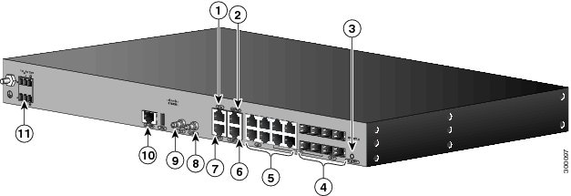
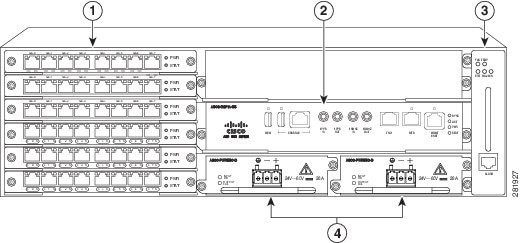
The Cisco ASR 9000v satellite shelf has 44 Gigabit Ethernet (GE) SFP ports and 4 10-GE SFP+ ports, which can be connected to the following line cards that support 10-GE interfaces:

  • The 24-port 10-GE SE or 24-port 10-GE TR line card
  • The 36-Port 10-GE SE or 36-Port 10-GE TR line card
  • The 80-GB modular line card when populated with 4-port 10-GE Modular Port Adapters (MPAs) or 2-port 10-GE MPAs
  • The 160-GB modular line card when populated with 8-port 10-GE MPAs, 4-port 10-GE MPAs, or 2-port 10-GE MPAs
  • The line cards that support 10-GE interfaces on the Cisco ASR 9922 Aggregation Services Router
  • The line cards that support 10-GE interfaces on the Cisco ASR 9001 Aggregation Services Router
  • The line cards that support 10-GE interfaces on the Cisco CRS Carrier Routing System 16-Slot Line Card Chassis and the Cisco CRS Carrier Routing System 8-Slot Line Card Chassis
    • CRS MSC-140G or FP-140G
    • 14-port 10-GE XFP PLIM
    • 20-port 10-GE XFP PLIM

For more information on the 10-GE line cards supported on the Cisco ASR 9000 Series Aggregation Services Router family, including the Cisco ASR 9922 Aggregation Services Router, see the Cisco ASR 9000 Series Aggregation Services Router Ethernet Line Card Installation Guide .

For more information on the 10-GE line cards supported on the Cisco ASR 9001 Aggregation Services Router, see the Cisco ASR 9001 Aggregation Services Router Hardware Installation Guide .

For more information on the 10-GE line cards supported on the Cisco CRS Carrier Routing System 16-Slot Line Card Chassis and the Cisco CRS Carrier Routing System 8-Slot Line Card Chassis, see the Cisco CRS Carrier Routing System Ethernet Physical Layer Interface Module Installation Note .
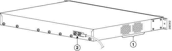
The Cisco ASR 9000v satellite shelf is one rack unit high. The Cisco ASR 9000v satellite shelf is typically connected to a fuse panel to provide distributed power for the Cisco ASR 9000v satellite shelf. The fuse panel is third-party equipment and is not described in this documentation. If you are unsure about the requirements or specifications for a fuse, consult the user documentation for the related equipment.

The Cisco ASR 9000v satellite shelf cannot operate independently. After connecting the Cisco ASR 9000v satellite shelf to the Cisco ASR 9000 Router or the Cisco CRS Line Card Chassis, the Cisco ASR 9000v satellite shelf is automatically discovered and registered.

The Cisco ASR 9000v satellite shelf supports Gigabit Ethernet and Fast Ethernet for ports numbered 0 to 43. Ports numbered 0 to 3 support 10 Gigabit Ethernet. By default, the four 10-GE ports numbered 0 to 3 are in IC mode and cannot be changed. The Cisco ASR 9000v satellite shelf also supports copper ports via copper SFPs and Active Cable copper SFP+ pluggables.

The Cisco ASR 9000v satellite shelf has redundant DC feeds. The Cisco ASR 9000v satellite shelf DC power supply can handle 48 V and 24 V. The 48-V power supply has both ANSI and ETSI versions. The 24-V power supply has ANSI version only.

The Cisco ASR 9000v satellite shelf has a removable fan tray and a local console port for onsite access and debugging.

Cisco ASR 9000v Satellite Shelf Faceplates

There are seven variations of the Cisco ASR 9000v satellite shelf faceplate:

  • Cisco ASR 9000v satellite shelf with AC power. See Figure 1.
  • Cisco ASR 9000v satellite shelf with DC ETSI 48 V. See Figure 2.
  • Cisco ASR 9000v satellite shelf with DC ANSI 24V. See Figure 3.
  • Cisco ASR 9000v satellite shelf with DC ANSI 48 V. See Figure 4.
  • Cisco ASR 9000v version 2 satellite shelf with AC power. Cisco ASR 9000v satellite shelf with AC power and Cisco ASR 9000v version 2 satellite shelf with AC power are similar. See Figure 1.
  • Cisco ASR 9000v version 2 satellite shelf with DC ETSI 48 V. Cisco ASR 9000v satellite shelf with DC ETSI 48 V and Cisco ASR 9000v version 2 satellite shelf with DC ETSI 48 V are similar. See Figure 2.
  • Cisco ASR 9000v version 2 satellite shelf with DC ANSI 48 V. Cisco ASR 9000v satellite shelf with DC ANSI 48 V and Cisco ASR 9000v version 2 satellite shelf with DC ANSI 48 V are similar. See Figure 4.
Figure 1. Cisco ASR 9000v Satellite Shelf with AC Power Faceplate
Figure 2. Cisco ASR 9000v Satellite Shelf with DC ETSI 48-V Faceplate
Figure 3. Cisco ASR 9000v Satellite Shelf with DC ANSI 24-V Faceplate
Figure 4. Cisco ASR 9000v Satellite Shelf with DC ANSI 48-V Faceplate

Cisco ASR 9000v Satellite Shelf Card–Level Indicators

This table describes the LEDs on the Cisco ASR 9000v satellite shelf cards.

Table 2. Cisco ASR 9000v Satellite Shelf Card–Level Indicators

Card-Level LED

Description

PWR

Indicates the status of the power to the card. If there is a power failure, this LED turns red.

FAN

Indicates the status of the fan to the card. If there is a fan failure, this LED turns red.

CRIT

Indicates the critical alarms in the network at the local terminal.

MAJ

Indicates the major alarms in the network at the local terminal.

MIN

Indicates the minor alarms in the network at the local terminal.

SFP Interface LEDs

This table gives information about the LEDs on the SFP interface.

Table 3. SFP LEDs

LED

Color/State

Description

SFP Link/Active (labeled LINK ACT)

Orange

Link and active indicator

Off

Link not enabled

Power Module

The Cisco ASR 9000v satellite shelf is available in four variations based on the power module:

  • Cisco ASR 9000v satellite shelf with an AC power module for ANSI and ETSI standards
  • Cisco ASR 9000v satellite shelf with a DC power module (24 V) for ANSI standard
  • Cisco ASR 9000v satellite shelf with a DC power module (48 V) for ANSI standard
  • Cisco ASR 9000v satellite shelf with a DC power module (48 V) for ETSI standard

The Cisco ASR 9000v version 2 satellite shelf is available in three variations based on the power module:

  • Cisco ASR 9000v version 2 satellite shelf with an AC power module for ANSI and ETSI standards
  • Cisco ASR 9000v version 2 satellite shelf with a DC power module (48 V) for ANSI standard
  • Cisco ASR 9000v version 2 satellite shelf with a DC power module (48 V) for ETSI standard

Note

Do not remove the top cover of the Cisco ASR 9000v satellite shelf.

Cisco ASR 9000v Satellite Shelf with an AC Power Module

The AC power module converts the AC input current to DC output current. The AC power module has one AC single phase with 3- pole (line L, Neutral N, and Protective Earth PE) input connector.

Cisco ASR 9000v Satellite Shelf with a DC Power Module

The Cisco ASR 9000v satellite shelf with a DC power module can be powered by redundant DC power lines, however a single power line can power the entire Cisco ASR 9000v satellite shelf.

The Cisco ASR 9000v satellite shelf with DC power module (24 V) for ANSI standard has single terminal block with four poles: –24V, RET for power terminals A and B.

The Cisco ASR 9000v satellite shelf with DC power module (48 V) for ANSI standard has single terminal block with four poles: –48V, RET for power terminals A and B.

The Cisco ASR 9000v satellite shelf with DC power module (48 V) for ETSI standard has two input battery connectors (two poles): –48V, RET for power terminals A and B.

Cisco ASR 901 Router Hardware Description

Contained in a standard shelf-rack enclosure, the Cisco ASR 901 Router weighs approximately 10 pounds (4 kg). It measures 1.7 inches high x 17.4 inches wide x 8.25 inches deep (4.32 cm [or 1RU] x 44.2 cm x 21.0 cm). These dimensions do not include the rack-mount brackets.

You can mount the router in a standard (ETSI) 19-inch (48.3 cm) equipment rack, a 600-mm ETSI rack, or a 23-inch ETSI rack.

The Cisco ASR 901 Router as a satellite shelf includes the following hardware features:

  • Four ports of 100/1000 copper Ethernet including auto-MDIX (RJ-45 connector)
  • Four ports of SFP only
  • Four combo ports (SFP/copper)
  • Dual feed supply with redundant DC inputs plus built-in redundant power supply (RPS)
  • Two fans placed in the chassis (fans are redundant)
  • Chassis: 1RU, 8.25-inch depth
  • Operating temperature range is –40 to +149°F (–40°C to +65°C).
  • Side-to-side airflow
  • Four solid-state alarm inputs
  • A single built-in 1-GB flash memory
  • Two management ports: an RS-232 serial console port and a 10/100 BASE-T Ethernet port
  • One BITS clock port (RJ-45) and 1 ToD port (RJ-45)
  • Two miniature coaxial connectors for 10-Mhz and 1-PPS timing (input or output). You can use these interfaces with an external GPS device to send or receive clocking from the router.
  • Two LEDs for each Ethernet port
    • L—Indicates activity, lack of activity, or no link
    • S—Indicates speed (100 or 1000) or off
  • One System LED:
    • Solid green—System healthy (normal operation)
    • Solid red—System faulty

Cisco ASR 901 Router Ethernet Version Front View

The figure below shows the front view of the Cisco ASR 901 Router, Ethernet version, with each interface module.

The front panel of the Cisco ASR 901 Router, Ethernet version, has the following components:

  • Eight RJ-45 jacks for copper Ethernet ports, labeled “100/1000” Ethernet
  • Eight SFP connectors for optical GE ports
  • Two miniature coaxial connectors for 10-MHz and 1-PPS timing
  • A single RJ-45 connector for console, labeled “CONSOLE”
  • A single RJ-45 jack for the BITS interface, labeled “BITS”
  • A single RJ-45 jack for the ToD interface, labeled “ToD”
  • A single alarm
  • Two management ports
  • The following LEDs:
    • Ethernet ports
    • SFP ports
    • Chassis: Single LED for multiple conditions

1

ToD Port

7

BITS Port

2

Management Port

8

MINI-Coax Connector (1 PPS)

3

Power LED

9

MINI-Coax Connector (10 MHz)

4

8 SFP Ports

10

Alarm

5

8 GE Ports

11

Power Connector

6

Console Port

The Cisco ASR 901 Router as a satellite shelf has 16 Gigabit Ethernet (8 RJ-45, 8 SFP) ports and one 10 Gigabit Ethernet SFP+ port. When running Cisco IOS XR software release 4.3 or 4.3.1, the Cisco ASR 901 Router as a satellite shelf can be connected to the following line cards that support Gigabit Ethernet interfaces:

  • 40-port GE line card
  • 40-port GE extended line card
  • 40-port GE low queue line card
  • Line cards that support Gigabit Ethernet interfaces on the Cisco ASR 9922 Aggregation Services Router
  • Line cards that support Gigabit Ethernet interfaces on the Cisco ASR 9001 Aggregation Services Router

Note

Only the last two SFP Gigabit Ethernet ports on the Cisco ASR 901 Router as a satellite shelf can support ICL (Inter-Chassis Link) mode.

Cisco ASR 901 Router Rear View

This figure below shows the rear view of the Cisco ASR 901 Router including the orientation of the following components:

  • Two blowing fans
  • Mounting point for the 2-hole lug
Figure 5. Cisco ASR 901 Router—Rear View

1

Fan

2

Grounding point lug

LEDs

The Cisco ASR 901 chassis and interface modules contain LEDs to assist in troubleshooting.

Chassis LEDs

This table summarizes the LEDs on the chassis of the Cisco ASR 901 router. These LEDs are common to the Cisco ASR 901 router used as a satellite shelf.

Table 4. LED Summary

LED

Color/State

Port Type

Description

Copper GE ports (from GE/FE Quad PHY) contain two LEDS each.

RJ-45 Link

L

Solid green

PHY

Link with no activity

Flashing green

Link with activity

Off

No link

RJ-45 Speed

S

Green

PHY

Speed 1000

Off

Off

Copper GE (from Quad combo PHY) ports contain two LEDS each.

RJ-45 Link

L

Solid green

PHY

Link with no activity

Flashing green

Link with activity

Off

No link

RJ-45 Speed

S

Green

PHY

Speed 1000

Off

Off

System LED

System

Off

HP

No power or unit not booted

Alternating green/off

POST in progress

Solid green

System healthy (normal operation

Solid red

System faulty

SFP LED

SFP Link-Active

L-A

Orange

HP

Link and active indicator

Off

Not enabled

SFP Ethernet Interface LEDs

This table gives information about the LEDs on the SFP interface.

Table 5. SFP LEDs

LED

Color/State

Description

SFP Link/Active (labeled LINK ACT)

Orange

Link and active indicator

Off

Link not enabled

RJ-45 Ethernet Interface LEDs

This table summarizes the LEDs on the RJ-45 Ethernet interface.

Table 6. 100/1000 Ethernet Port LEDs

LED

Color/State

Description (Two LEDs for Each 100/1000 Ethernet Port)

100/1000 RJ-45 link (labeled L, left LED)

Solid Green

Link with no activity

Flashing Green

Link with activity

Off

No link detected

100/1000 RJ-45 speed (labeled S, right LED)

Green

Speed 1000

Yellow

Speed 100

Off

Off

Where to Go Next

For more information on installing the Cisco ASR 901 Series Aggregation Services Router as a satellite shelf, see Chapter 3, “Installing the Cisco ASR 901 Mobile Wireless Router as a Satellite Shelf.”

Cisco ASR 903 Router Hardware Description

The Cisco ASR 903 Router has the following hardware features:

  • 3-RU modular chassis designed for installation in a 300-mm European Telecommunications Standards Institute (ETSI) cabinet
  • Dedicated slots in the chassis that support the following:
    • Up to six interface modules
    • Up to two Route Switch Processors (RSPs)

Note

When configured as an ASR 903v satellite shelf, the Cisco ASR 903 Router supports only one Route Switch Processor (RSP).
    • Up to two AC power supply units

or

    • Up to two DC power supply units

Note

You cannot mix AC and DC power supply units in the Cisco ASR 903 Router.
    • One fan tray
  • Network frequency, phase, and time inputs and outputs for network interfaces (SyncE and TDM), BITS, 1 PPS or 10 MHz, and Timing over Packet (IEEE 1588-2008)

Note

When configured as a satellite shelf, the Cisco ASR 903 Router does not support SyncE and timing features.
  • Adjustable front and rear rail mounting locations
  • Front panel access to power supplies, fan tray, RSPs, and interface modules
  • Online insertion and removal (OIR) of power supplies and fan tray
  • Discrete status LEDs on power supply, interface module, RSP, and fan tray units
  • Four alarm dry contact inputs (either normally open or normally closed)
  • Environmental monitoring and reporting functions
  • LED indicators for critical, major, and minor alarms
  • Side-to-side forced air cooling
  • Temperature range of –40 to +149 °F (–40 to 65°C) with DC power supply
  • Temperature range of –32 to +104 °F (0 to 40°C) with AC power supply

Cisco ASR 903 Router Front View

This figure illustrates the Cisco ASR 903 Router chassis design.

Figure 6. Cisco ASR 903 Chassis Design

1

Interface modules

3

Fan tray

2

RSP unit

4

Redundant power units (two DC power units shown)

The Cisco ASR 903 Router as a satellite shelf supports the following Ethernet interface modules:

  • 8-Port Gigabit Ethernet SFP Interface Module
  • 8-Port Gigabit Ethernet RJ-45 Interface Module
  • 1-Port 10 Gigabit Ethernet XFP Interface Module

The Cisco ASR 903 Router as a satellite shelf can support up to two 10 Gigabit Ethernet XFP ports (restricted to slots 0 and 1) and up to 31 Gigabit Ethernet (either RJ-45 or SFP) ports (8-port interface modules in slots 2 through 5). In slot 5, only seven ports can be activated. Port 0 on slot 5 cannot be used as a satellite port because it is used for the internal FPGA. The two 10 Gigabit Ethernet XFP ports can be used as ICL ports when they are connected to the following line cards that support 10 Gigabit Ethernet interfaces:

  • 24-port 10-GE SE or 24-port 10-GE TR line card
  • 36-Port 10-GE SE or 36-Port 10-GE TR line card
  • 80-GB modular line card when populated with 4-port 10-GE Modular Port Adapters (MPAs) or 2-port 10-GE MPAs
  • 160-GB modular line card when populated with 4-port 10-GE MPAs or 2-port 10-GE MPAs
  • Line cards that support 10 Gigabit Ethernet interfaces on the Cisco ASR 9922 Aggregation Services Router
  • Line cards that support 10 Gigabit Ethernet interfaces on the Cisco ASR 9001 Aggregation Services Router

LEDs

The following sections describe the meanings of the LEDs on the Cisco ASR 903 Router satellite shelf.

RSP LEDs

This table summarizes the RSP LEDs.


Note

A major alarm condition indicates the failure of a single fan in the fan tray; a critical alarm indicates the failure of multiple fans. If a single fan fails, the Cisco ASR 903 Router satellite shelf software adjusts the fan speed to prevent excessive heat within the chassis.
Table 7. RSP LEDs

LED

Color/State

Description (Two LEDs for Each T1/E1 Port)

Power (PWR)

Off

Disabled/no power to RSP

Green

Power rails on RSP in range

Status (STAT)

Off

Disabled/power down

Red

Failure to boot (lit at reset)

Yellow

Rommon booted

Green

Cisco IOS software booted and running

Active (ACTV)

Off

Not available

Yellow

Standby (indicates standby RSP)

Green

Active (indicates active RSP)

Management port (MGMT)

Off

No connection

Green

Connected with no activity

Flashing green

Connected with activity

Sync status (SYNC)

Off

Not enabled

Yellow

Free run

Flashing yellow

Holdover

Green

Locked to source

USB flash (MEM)

Flashing green

USB activity

BITS

Off

Out of service/not configured

Amber

Fault or loop condition

Green

In frame/working properly

Interface Module LEDs

This table below summarizes the interface module LEDs. This LED summary applies to the following interface modules:

  • SFP Gigabit Ethernet Interface Module

  • RJ-45 Gigabit Ethernet Interface Module

  • XFP 10 Gigabit Ethernet XFP Interface Module

Table 8. Interface Module LEDs

LED

Color/State

Description

Power (PWR)

Off

Disabled/no power to IM

Green

Enabled and power rails on IM in range

Status (STAT)

Off

Disabled/power-down

Red

Failure (on at reset)

Amber

Booting (if local CPU)

Green

Operational

Link status (L)

Off

Inactive or no connection

Amber

Fault/loop condition

Green

Ok with no activity

Flashing green

OK with activity

Speed (S)

Off

100/10 Mbps/Slow

Green

1 Gbps/Full

Power Supply LEDs

These tables below summarize the power supply LEDs for the AC and DC power supplies.

Table 9. AC Power Supply LEDs

LED

Color/State

Description

Input OK

Off

No input voltage

Amber

Input voltage out of range

Green

Input voltage within acceptable operating range

Output Fail

Off

Disabled/Forced shut down/No input power

Red

Power supply fault (internal failure such as overtemperature)

Green

Operational

Table 10. DC Power Supply LEDs

LED

Color/State

Description

Input Power (PWR)

Off

No input voltage

Amber

Input voltage out of range

Green

Input voltage within acceptable operating range

Status (STAT)

Off

Disabled/power down/no power

Red

Power supply fault (internal failure)

Green

Operational

Fan Tray LEDs

This table summarizes the fan tray LEDs.

Table 11. Fan Tray LEDs

LED

Color/State

Description

Status (TEMP)

Off

Disabled/power down

Amber

Overtemperature

Green

OK

Fan (FAN)

Green

Fan rotation in range

Amber

Fan fault

Red

Two or more fan faults

Minor (MIN)

Off

No minor alarm

Amber

Minor alarm

Major (MAJ)

Off

No major alarm

Red

Major alarm

Where to Go Next

For more information on installing the Cisco ASR 903 Series Aggregation Services Router as a satellite shelf, see Chapter 4, “Installing the Cisco ASR 903 Router as a Satellite Shelf.”