Installing and Removing the SFP+, CPAK, and QSFP Modules
This chapter describes how to install and remove small form-factor pluggable (SFP+), CPAK, and QSFP modules in the EPAs. This chapter contains the following sections:
Preparing for Online Removal of SFP+, CPAK, and QSFP Modules
The Cisco ASR 1000 series router support OIR of an SFP+, CPAK, or a QSFP module without removing the EPA or MIP.
The interface configuration is retained or recalled if an EPA, MIP, SFP+, or CPAK is removed and then replaced with one of the same type.
However, if the line card is already installed in the router and the system is operational, we recommend that you shut down the port using the interface config command before removing the SFP+, or CPAK, or QSFP modules.
Installing and Removing SFP+ Modules

Note![]() The EPA supports only the SFP+ modules listed in the “Modular Optics Compatibilities” section. An SFP+ check is run every time an SFP+ module is inserted into an EPA, and only those SFP+ modules that pass this check are usable.
The EPA supports only the SFP+ modules listed in the “Modular Optics Compatibilities” section. An SFP+ check is run every time an SFP+ module is inserted into an EPA, and only those SFP+ modules that pass this check are usable.
Before you remove or install an SFP+ module, read the installation information provided in this section and the “Laser and LED Safety” section.

Removing and inserting an SFP+ module can shorten its useful life. Therefore, you should not remove and insert SFP+ modules unless it is absolutely necessary.
SFP+ modules use one of four different latching devices to install and remove the module from a port. The four types of SFP+ module-latching devices are described in the following sections:
Bale Clasp SFP+ Module
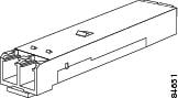
The bale clasp SFP+ module has a clasp that you should use to remove or install the SFP+ module. (See Figure 5-1.)
Figure 5-1 Bale Clasp SFP+ Module
Installing a Bale Clasp SFP+ Module
To install this type of SFP+ module, follow these steps:
Step 1![]() Attach an ESD-preventive wrist strap or ankle strap according to the instructions provided.
Attach an ESD-preventive wrist strap or ankle strap according to the instructions provided.
Step 2![]() Close the bale clasp before inserting the SFP+ module.
Close the bale clasp before inserting the SFP+ module.
Step 3![]() Line up the SFP+ module with the port, and slide it into the port. (See Figure 5-2.)
Line up the SFP+ module with the port, and slide it into the port. (See Figure 5-2.)
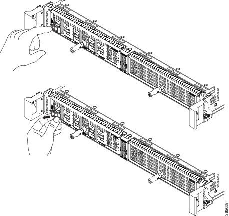
Figure 5-2 Installing a Bale Clasp SFP+ Module into a Port
Note![]() Verify that the SFP+ modules are completely seated and secured in their assigned receptacles on the line card by firmly pushing on each SFP+ module. If the SFP+ module is not completely seated and secured in the receptacle, you will hear a click as the triangular pin at the bottom of the SFP+ module snaps into the hole in the receptacle.
Verify that the SFP+ modules are completely seated and secured in their assigned receptacles on the line card by firmly pushing on each SFP+ module. If the SFP+ module is not completely seated and secured in the receptacle, you will hear a click as the triangular pin at the bottom of the SFP+ module snaps into the hole in the receptacle.
Removing a Bale Clasp SFP+ Module
To remove this type of SFP+ module, follow these steps:
Step 1![]() Attach an ESD-preventive wrist strap or ankle strap by following the instructions provided.
Attach an ESD-preventive wrist strap or ankle strap by following the instructions provided.
Step 2![]() Disconnect and remove all the interface cables from the ports and note the current connections of the cables to the ports on the line card.
Disconnect and remove all the interface cables from the ports and note the current connections of the cables to the ports on the line card.
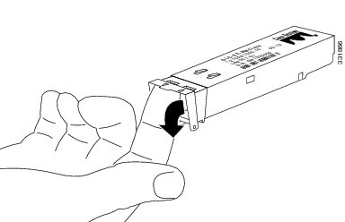
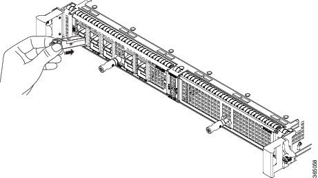
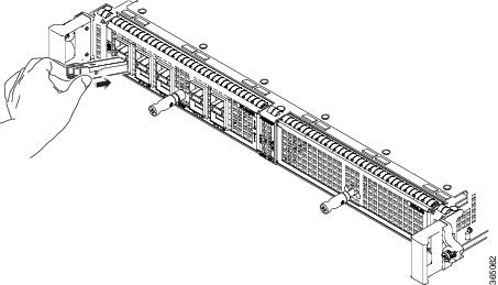
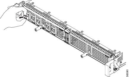
Step 3![]() Open the bale clasp on the SFP+ module with your index finger in a downward direction, as shown in Figure 5-3. If the bale clasp is obstructed and you cannot use your index finger to open it, use a small flat-blade screwdriver to open the bale clasp.
Open the bale clasp on the SFP+ module with your index finger in a downward direction, as shown in Figure 5-3. If the bale clasp is obstructed and you cannot use your index finger to open it, use a small flat-blade screwdriver to open the bale clasp.
Step 4![]() Grasp the SFP+ module between your thumb and index finger and carefully remove it from the port as shown in Figure 5-3.
Grasp the SFP+ module between your thumb and index finger and carefully remove it from the port as shown in Figure 5-3.
Figure 5-3 Removing a Bale Clasp SFP+ Module
Step 5![]() Place the removed SFP+ module on an antistatic mat, or immediately place it in a static shielding bag if you plan to return it to the factory.
Place the removed SFP+ module on an antistatic mat, or immediately place it in a static shielding bag if you plan to return it to the factory.
Step 6![]() Protect your line card by inserting clean SFP+ module cage covers into the optical module cage when no SFP+ modules are installed.
Protect your line card by inserting clean SFP+ module cage covers into the optical module cage when no SFP+ modules are installed.
Mylar Tab SFP+ Module
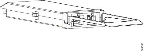
The mylar tab SFP+ module has a tab that you pull to remove the module from a port. (See Figure 5-4.)
Figure 5-4 Mylar Tab SFP+ Module
Installing a Mylar Tab SFP+ Module
To install this type of SFP+ module, follow these steps:
Step 1![]() Attach an ESD-preventive wrist strap or ankle strap according to the instructions provided.
Attach an ESD-preventive wrist strap or ankle strap according to the instructions provided.
Step 2![]() Line up the SFP+ module with the port, and slide it into place. (See Figure 5-5.)
Line up the SFP+ module with the port, and slide it into place. (See Figure 5-5.)
Figure 5-5 Installing a Mylar Tab SFP+ Module
Note![]() Verify that the SFP+ modules are completely seated and secured in their assigned receptacles on the line card by firmly pushing on each SFP+ module. If the SFP+ module is not completely seated and secured in the receptacle, you will hear a click as the triangular pin at the bottom of the SFP+ module snaps into the hole in the receptacle.
Verify that the SFP+ modules are completely seated and secured in their assigned receptacles on the line card by firmly pushing on each SFP+ module. If the SFP+ module is not completely seated and secured in the receptacle, you will hear a click as the triangular pin at the bottom of the SFP+ module snaps into the hole in the receptacle.
Removing a Mylar Tab SFP+ Module
To remove this type of SFP+ module, follow these steps:
Step 1![]() Attach an ESD-preventive wrist strap or ankle strap according to the instructions provided.
Attach an ESD-preventive wrist strap or ankle strap according to the instructions provided.
Step 2![]() Disconnect and remove all the interface cables from the ports; note the current connections of the cables to the ports on the line card.
Disconnect and remove all the interface cables from the ports; note the current connections of the cables to the ports on the line card.
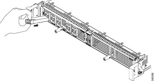
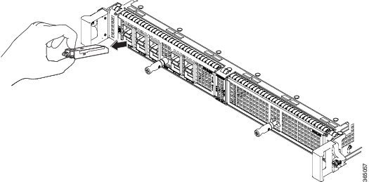
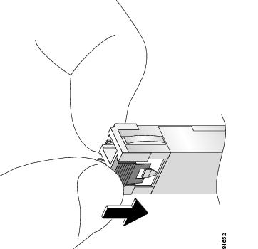
Step 3![]() Pull the tab gently in a slightly downward direction until it disengages from the port and then pull the SFP+ module out. (See Figure 5-6.)
Pull the tab gently in a slightly downward direction until it disengages from the port and then pull the SFP+ module out. (See Figure 5-6.)
Figure 5-6 Removing a Mylar Tab SFP+ Module
Step 4![]() Place the removed SFP+ module on an antistatic mat, or immediately place it in a static shielding bag if you plan to return it to the factory.
Place the removed SFP+ module on an antistatic mat, or immediately place it in a static shielding bag if you plan to return it to the factory.
Step 5![]() Protect your line card by inserting clean SFP+ module cage covers on the optical module cage when there is no SFP+ module installed.
Protect your line card by inserting clean SFP+ module cage covers on the optical module cage when there is no SFP+ module installed.
Actuator Button SFP+ Module
The actuator button SFP+ module includes a button that you should push in order to remove the SFP+ module from a port. (See Figure 5-7.)
Figure 5-7 Actuator Button SFP+ Module
Installing an Actuator Button SFP+ Module
To install this type of SFP+ module, follow these steps:
Step 1![]() Attach an ESD-preventive wrist strap or ankle strap according to the instructions provided.
Attach an ESD-preventive wrist strap or ankle strap according to the instructions provided.
Step 2![]() Line up the SFP+ module with the port and slide it in until the actuator button clicks into place. (See Figure 5-8.) Do not press the actuator button as you insert the SFP+ module because you might inadvertently disengage the SFP+ module from the port.
Line up the SFP+ module with the port and slide it in until the actuator button clicks into place. (See Figure 5-8.) Do not press the actuator button as you insert the SFP+ module because you might inadvertently disengage the SFP+ module from the port.
Figure 5-8 Installing an Actuator Button SFP+ Module
Note![]() Verify that the SFP+ modules are completely seated and secured in their assigned receptacles on the line card by firmly pushing on each SFP+ module. If the SFP+ module is not completely seated and secured in the receptacle, you will hear a click as the triangular pin at the bottom of the SFP+ module snaps into the hole in the receptacle.
Verify that the SFP+ modules are completely seated and secured in their assigned receptacles on the line card by firmly pushing on each SFP+ module. If the SFP+ module is not completely seated and secured in the receptacle, you will hear a click as the triangular pin at the bottom of the SFP+ module snaps into the hole in the receptacle.
Removing an Actuator Button SFP+ Module
To remove this type of SFP+ module, follow these steps:
Step 1![]() Attach an ESD-preventive wrist strap or ankle strap according to the instructions provided.
Attach an ESD-preventive wrist strap or ankle strap according to the instructions provided.
Step 2![]() Disconnect and remove all the interface cables from the ports; note the current connections of the cables to the ports on the line card.
Disconnect and remove all the interface cables from the ports; note the current connections of the cables to the ports on the line card.
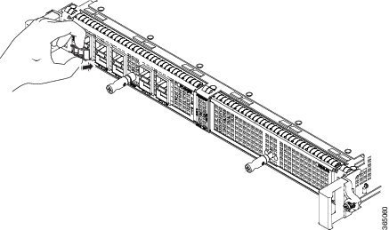
Step 3![]() Gently press the actuator button on the front of the SFP+ module until it clicks and the latch mechanism is activated, releasing the SFP+ module from the port. (See Figure 5-9.)
Gently press the actuator button on the front of the SFP+ module until it clicks and the latch mechanism is activated, releasing the SFP+ module from the port. (See Figure 5-9.)
Figure 5-9 Removing an Actuator Button SFP+ Module from a Port
Step 4![]() Grasp the actuator button between your thumb and index finger and carefully pull the SFP+ module from the port.
Grasp the actuator button between your thumb and index finger and carefully pull the SFP+ module from the port.
Step 5![]() Place the removed SFP+ module on an antistatic mat, or immediately place it in a static shielding bag if you plan to return it to the factory.
Place the removed SFP+ module on an antistatic mat, or immediately place it in a static shielding bag if you plan to return it to the factory.
Step 6![]() Protect your line card by inserting clean SFP+ module cage covers on the optical module cage when there is no SFP+ module installed.
Protect your line card by inserting clean SFP+ module cage covers on the optical module cage when there is no SFP+ module installed.
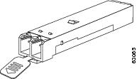
Slide Tab SFP+ Module
The slide tab SFP+ module has a tab underneath the front of the SFP+ module. Use the tab to disengage the module from a port. (See Figure 5-10.)
Figure 5-10 Slide Tab SFP+ Module
Installing a Slide Tab SFP+ Module
To install this type of SFP+ module, follow these steps:
Step 1![]() Attach an ESD-preventive wrist strap or ankle strap according to the instructions provided.
Attach an ESD-preventive wrist strap or ankle strap according to the instructions provided.
Step 2![]() Hold the SFP+ module with the hardware label facing up.
Hold the SFP+ module with the hardware label facing up.
Step 3![]() Insert the SFP+ module into the appropriate slot and gently push on it until it snaps into the slot tightly. (See Figure 5-11.)
Insert the SFP+ module into the appropriate slot and gently push on it until it snaps into the slot tightly. (See Figure 5-11.)
Figure 5-11 Installing a Slide Tab SFP+ Module
Note![]() Verify that the SFP+ modules are completely seated and secured in their assigned receptacles on the line card by firmly pushing on each SFP+ module. If the SFP+ module is not completely seated and secured in the receptacle, you will hear a click as the triangular pin on the bottom of the SFP+ module snaps into the hole in the receptacle.
Verify that the SFP+ modules are completely seated and secured in their assigned receptacles on the line card by firmly pushing on each SFP+ module. If the SFP+ module is not completely seated and secured in the receptacle, you will hear a click as the triangular pin on the bottom of the SFP+ module snaps into the hole in the receptacle.
Removing a Slide Tab SFP+ Module
To remove this type of SFP+ module, follow these steps:
Step 1![]() Attach an ESD-preventive wrist strap or ankle strap according to the instructions provided.
Attach an ESD-preventive wrist strap or ankle strap according to the instructions provided.
Step 2![]() Disconnect and remove all the interface cables from the ports; note the current connections of the cables to the ports on the line card.
Disconnect and remove all the interface cables from the ports; note the current connections of the cables to the ports on the line card.
Step 3![]() Grasp the SFP+ module between your thumb and index finger.
Grasp the SFP+ module between your thumb and index finger.
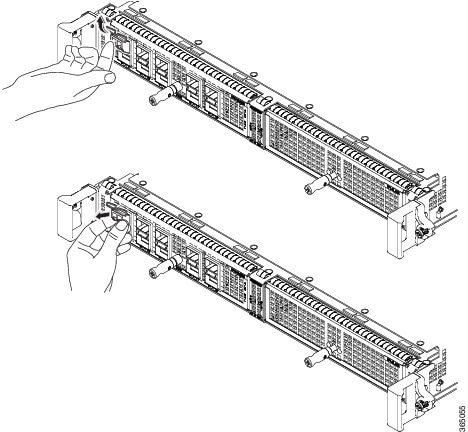
Step 4![]() With your thumb, push the slide tab at the bottom front of the SFP+ module in the direction of the line card to disengage the module from the line card port. (See Figure 5-12.)
With your thumb, push the slide tab at the bottom front of the SFP+ module in the direction of the line card to disengage the module from the line card port. (See Figure 5-12.)
Figure 5-12 Disengaging the Slide Tab
Step 5![]() With the tab still pushed, carefully pull the SFP+ module from the port, as shown in Figure 5-13.
With the tab still pushed, carefully pull the SFP+ module from the port, as shown in Figure 5-13.
Figure 5-13 Removing a Slide Tab SFP+ Module
Step 6![]() Place the removed SFP+ module on an antistatic mat, or immediately place it in a static shielding bag if you plan to return it to the factory.
Place the removed SFP+ module on an antistatic mat, or immediately place it in a static shielding bag if you plan to return it to the factory.
Step 7![]() Protect your line card by inserting clean SFP+ module cage covers on the optical module cage when there is no SFP+ module installed.
Protect your line card by inserting clean SFP+ module cage covers on the optical module cage when there is no SFP+ module installed.
Installing and Removing CPAK Modules
The CPAK transceiver module is a hot-swappable I/O device that plugs into the 1-Port 100 Gigabit Ethernet EPA (EPA-1X100GE). The modules have a total of 82 pins (40 pins on the top row and 42 on the bottom row) on the electrical interface and either a duplex SC or 24 fibers-MPO connector on the optical interface.
The following types of CPAK modules or adapters are supported:
Delivers 100-Gbps links over 24-fiber ribbon cables terminated with MPO/MTP connectors. It supports link lengths of 100m and 150m on laser-optimized OM3 and OM4 multifiber cables.
Note![]() The EPA-CPAK-2x40GE supports only the CPAK-100G-SR10 and CAB-MPO24-2XMPO12 (breakout cable).
The EPA-CPAK-2x40GE supports only the CPAK-100G-SR10 and CAB-MPO24-2XMPO12 (breakout cable).
Supports 100-Gbps optical links over standard single-mode fiber (SMF, G.652) terminated with SC connectors. Nominal power consumption is less than 5.5W.
The LR4 module is IEEE 802.3ba-compliant and supports link lengths of up to 10 km over standard SMF, G.652. It delivers an aggregate data signal of 100-Gbps, carried over four wavelength-division multiplexing (WDM) wavelengths operating at a nominal 25 Gbps per lane in LAN mode. Optical multiplexing and demultiplexing of the four wavelengths are managed within the module.
Supports 100-Gbps optical links over standard single-mode fiber (SMF, G.652) terminated with SC connectors. Nominal power consumption is less than 5.5W.
The LR4 module is IEEE 802.3ba-compliant and supports link lengths of up to 25 km over standard SMF, G.652. It delivers an aggregate data signal of 100-Gbps, carried over four wavelength-division multiplexing (WDM) wavelengths operating at a nominal 25 Gbps per lane in LAN mode. Optical multiplexing and demultiplexing of the four wavelengths are managed within the module.
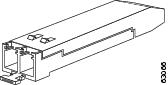
Figure 5-14 100-Gigabit Ethernet CPAK Transceiver Module
Installing the CPAK Module
To install an CPAK transceiver, follow these steps:
Step 1![]() Attach an ESD wrist strap to yourself and a properly grounded point on the chassis or the rack.
Attach an ESD wrist strap to yourself and a properly grounded point on the chassis or the rack.
Step 2![]() Remove the CPAK transceiver from its protective packaging.
Remove the CPAK transceiver from its protective packaging.
Note![]() Do not remove the optical bore dust plugs until directed to do so later in the procedure.
Do not remove the optical bore dust plugs until directed to do so later in the procedure.
Step 3![]() Check the label on the CPAK transceiver body to verify that you have the correct model for your network.
Check the label on the CPAK transceiver body to verify that you have the correct model for your network.
Step 4![]() Remove the optical bore dust plug and set it aside.
Remove the optical bore dust plug and set it aside.
Step 5![]() Align the CPAK module in front of the module’s socket opening and carefully slide the CPAK module into the socket until the module makes contact with the socket electrical connector.
Align the CPAK module in front of the module’s socket opening and carefully slide the CPAK module into the socket until the module makes contact with the socket electrical connector.
Step 6![]() Press firmly on the front of the CPAK module with your thumb to fully seat the module in the module’s socket.
Press firmly on the front of the CPAK module with your thumb to fully seat the module in the module’s socket.
Step 7![]() Reinstall the dust plug into the CPAK transceiver or adapter module optical bore until you are ready to attach the network interface cable. Do not remove the dust plug until you are ready to attach the network interface cable.
Reinstall the dust plug into the CPAK transceiver or adapter module optical bore until you are ready to attach the network interface cable. Do not remove the dust plug until you are ready to attach the network interface cable.
Attaching the Optical Network Cable
Before removing the dust plugs and making any optical connections, follow these guidelines:
- Always keep the protective dust plugs on the unplugged fiber-optic cable connectors and the transceiver optical bores until you are ready to make a connection.
- Inspect and clean the MPO connector end faces just before you make any connections. See the “Cleaning Optical Devices” section for information about fiber-optic inspection and cleaning.
- Grasp the MPO connector only by the housing to plug or unplug a fiber-optic cable.
Note![]() For the CPAK-100G-SR10 module, the multiple-fiber push-on (MPO) connectors use network interface cables with either physical contact (PC) or ultra-physical contact (UPC) flat polished face types.
For the CPAK-100G-SR10 module, the multiple-fiber push-on (MPO) connectors use network interface cables with either physical contact (PC) or ultra-physical contact (UPC) flat polished face types.
Step 1![]() Remove the dust plugs from the optical network interface cable connectors. Save the dust plugs for future use.
Remove the dust plugs from the optical network interface cable connectors. Save the dust plugs for future use.
Step 2![]() Inspect and clean the connector’s fiber-optic end faces.
Inspect and clean the connector’s fiber-optic end faces.

Tip For complete information on inspecting and cleaning fiber-optic connections, see the “Cleaning Optical Devices” section.
Step 3![]() Remove the dust plugs from the CPAK transceiver module optical bores.
Remove the dust plugs from the CPAK transceiver module optical bores.
Step 4![]() Immediately attach the network interface cable connectors to the CPAK module.
Immediately attach the network interface cable connectors to the CPAK module.
Removing the CPAK Transceiver Module
To remove an CPAK transceiver, follow these steps:
Step 1![]() Disconnect the network interface cable from the CPAK transceiver connectors.
Disconnect the network interface cable from the CPAK transceiver connectors.
Step 2![]() Immediately install the dust plug into the module’s optical bore.
Immediately install the dust plug into the module’s optical bore.
Step 3![]() Grasp the tab and gently pull straight out to release the module from the socket.
Grasp the tab and gently pull straight out to release the module from the socket.
Installing and Removing QSFP Modules
The QSFP transceiver module is a hot-swappable I/O device that supports 40-Gbps optical links over standard single-mode fiber (SMF, G.652) terminated with SC connectors. Nominal power consumption is less than 3.5W.
The LR4 module is IEEE 802.3ba-compliant and supports link lengths of up to 10 km over standard SMF, G.652. It delivers an aggregate data signal of 40-Gbps, carried over four wavelength-division multiplexing (WDM) wavelengths operating at a nominal 10 Gbps per lane in LAN mode. 40-Gigabit Ethernet QSFP Transceiver Module
Installing the QSFP Module
To install an QSFP transceiver, follow these steps:
Step 1![]() Attach an ESD wrist strap to yourself and a properly grounded point on the chassis or the rack.
Attach an ESD wrist strap to yourself and a properly grounded point on the chassis or the rack.
Step 2![]() Remove the QSFP transceiver from its protective packaging.
Remove the QSFP transceiver from its protective packaging.
Note![]() Do not remove the optical bore dust plugs until directed to do so later in the procedure.
Do not remove the optical bore dust plugs until directed to do so later in the procedure.
Step 3![]() Check the label on the QSFP transceiver body to verify that you have the correct model for your network.
Check the label on the QSFP transceiver body to verify that you have the correct model for your network.
Step 4![]() Remove the optical bore dust plug and set it aside.
Remove the optical bore dust plug and set it aside.
Step 5![]() Align the QSFP module in front of the module’s socket opening and carefully slide the QSFP module into the socket until the module makes contact with the socket electrical connector.
Align the QSFP module in front of the module’s socket opening and carefully slide the QSFP module into the socket until the module makes contact with the socket electrical connector.
Step 6![]() Press firmly on the front of the QSFP module with your thumb to fully seat the module in the module’s socket.
Press firmly on the front of the QSFP module with your thumb to fully seat the module in the module’s socket.
Step 7![]() Reinstall the dust plug into the QSFP transceiver or adapter module optical bore until you are ready to attach the network interface cable. Do not remove the dust plug until you are ready to attach the network interface cable.
Reinstall the dust plug into the QSFP transceiver or adapter module optical bore until you are ready to attach the network interface cable. Do not remove the dust plug until you are ready to attach the network interface cable.
Attaching the Optical Network Cable
Step 1![]() Remove the dust plugs from the optical network interface cable connectors. Save the dust plugs for future use.
Remove the dust plugs from the optical network interface cable connectors. Save the dust plugs for future use.
Step 2![]() Inspect and clean the connector’s fiber-optic end faces.
Inspect and clean the connector’s fiber-optic end faces.
Tip For complete information on inspecting and cleaning fiber-optic connections, see the “Cleaning Optical Devices” section.
Step 3![]() Remove the dust plugs from the QSFP transceiver module optical bores.
Remove the dust plugs from the QSFP transceiver module optical bores.
Step 4![]() Immediately attach the network interface cable connectors to the QSFP module.
Immediately attach the network interface cable connectors to the QSFP module.
Removing the QSFP Transceiver Module
To remove an QSFP transceiver, follow these steps:
Step 1![]() Disconnect the network interface cable from the QSFP transceiver connectors.
Disconnect the network interface cable from the QSFP transceiver connectors.
Step 2![]() Immediately install the dust plug into the module’s optical bore.
Immediately install the dust plug into the module’s optical bore.
Step 3![]() Grasp the tab and gently pull straight out to release the module from the socket.
Grasp the tab and gently pull straight out to release the module from the socket.
Step 4![]() Slide the module out of the socket.
Slide the module out of the socket.
Step 5![]() Place the QSFP module into an antistatic bag.
Place the QSFP module into an antistatic bag.
Optical Device Maintenance
Any contamination of the fiber connection can cause failure of the component or failure of the whole system. A particle that partially or completely blocks the core generates strong back reflections, which can cause instability in the laser system. Inspection, cleaning, and reinspection are critical steps to take before making fiber-optic connections.
Cleaning Optical Devices
See the Inspection and Cleaning Procedures for Fiber-Optic Connections and the Compressed Air Cleaning Issues for Fiber-Optic Connections documents for information on cleaning optical devices.
 Feedback