Installing and Removing an EPA
This chapter describes how to install or remove Ethernet port adapters (EPAs) in a MIP. This chapter contains the following sections:
Handling EPAs
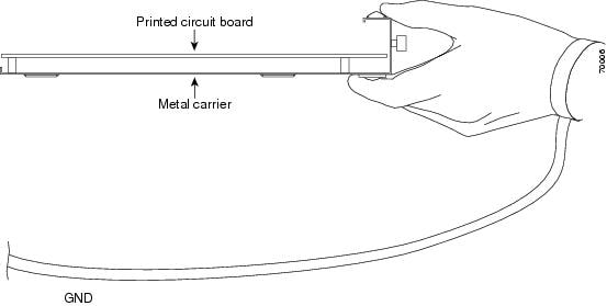
Each EPA circuit board is mounted to a metal carrier and is sensitive to electrostatic discharge (ESD) damage. See the “Preventing Electrostatic Discharge Damage” section for ESD precautions.
Before you begin installation, read Chapter 2, “Preparing to Install a MIP or EPA”, for a list of parts and tools required for installation.

When a subslot is not in use, an EPA blank filler plate must fill the empty subslot to allow the router to conform to electromagnetic interference (EMI) emissions requirements and to allow proper airflow across the EPAs. If you plan to install an EPA in a subslot that is not in use, you must first remove the EPA blank filler plate.
Online Insertion and Removal
The Cisco ASR 1000 Series Routers support the OIR of an EPA independent of removing the MIP. This means that a MIP can remain installed in the Cisco ASR 1000 Series Router with one EPA remaining active, while you remove another EPA from one of the MIP subslots. If you are not planning to immediately replace an EPA into the MIP, ensure that you install a blank filler plate in the subslot. The MIP should always be fully installed with either functional EPAs or blank filler plates.
If you are planning to remove a MIP along with its EPAs, you do not have to follow the instructions provided in this section. To remove a MIP, see the “Preparing for Online Removal of the MIP” section.
This section includes the following topics on OIR support:
- Preparing for Online Removal of the EPA
- Deactivating EPA
- Reactivating EPA
- Verifying the Deactivation and Activation of the EPA
Preparing for Online Removal of the EPA
The Cisco ASR 1000 series router support OIR of the EPA. If you plan to remove an EPA, deactivate the EPA first using the hw-module subslot slotnumber / subslotnumber shutdown global configuration command.
When you deactivate the EPA using this command, it automatically deactivates each of the SFP+ or CPAK modules that are installed in the EPA. Therefore, it is not necessary to deactivate each of the SFP+ or CPAK modules prior to deactivating the EPA.
Although graceful deactivation of the EPA is preferred using the hw-module subslot slotnumber / subslotnumber shutdown command, the Cisco ASR 1000 series router do support the removal of the EPA without deactivating it first.
Deactivating EPA
To deactivate an EPA and its installed SFP+, CPAK or QSFP modules prior to the removal of the EPA, use the following command in the global configuration mode:
|
|
|
|---|---|
|
|
Shuts down the installed interfaces and deactivates the EPA in the specified slot and subslot of the MIP, where: |
Reactivating EPA
After you deactivate the EPA, whether or not you have performed an OIR, you must use the no hw-module slot slotnumber / subslotnumber shutdown global configuration command to reactivate the EPA. The installed SFP+, CPAK or QSFP modules automatically get reactivated upon reactivation of the EPA in the router.
To reactivate a EPA and its installed SFP+, CPAK or QSFP modules after the EPA has been deactivated, use the following command in the global configuration mode:
Verifying the Deactivation and Activation of the EPA
To verify the deactivation of the EPA, enter the show hw-module subslot all oir command in the privileged EXEC configuration mode. Observe the State field associated with the EPA that you want to verify.
The following example shows the EPA located in slot 1, subslot 1 as administratively down.
To verify the activation and proper operation of an EPA, enter the show hw-module subslot all oir and observe slot 1, subslot 0, in the ok state, as shown in the following example:
EPA Installation and Removal
This section provides step-by-step instructions for installing and removing an EPA in a MIP.
To install an EPA in a MIP, refer to Figure 4-2 and do the following:
Step 1![]() To insert the EPA in the MIP, locate the guide rails inside the MIP that hold the EPA in place.
To insert the EPA in the MIP, locate the guide rails inside the MIP that hold the EPA in place.
Step 2![]() Align the EPA with the guide rails and carefully slide the EPA all the way into the MIP slot until the EPA stops.
Align the EPA with the guide rails and carefully slide the EPA all the way into the MIP slot until the EPA stops.
Step 3![]() Use a number 2 Phillips screwdriver to fully seat the EPA by turning the captive screw clockwise. When fully seated, the EPA should be flush with the MIP faceplate.
Use a number 2 Phillips screwdriver to fully seat the EPA by turning the captive screw clockwise. When fully seated, the EPA should be flush with the MIP faceplate.

Note![]() Avoid over torquing the EPA captive screw when installing the EPA. Tighten the captive screw on the EPA to a torque of 11 +/-1 inch-pounds.
Avoid over torquing the EPA captive screw when installing the EPA. Tighten the captive screw on the EPA to a torque of 11 +/-1 inch-pounds.
To remove the EPA from the MIP, refer to Figure 4-2 and do the following:
Step 1![]() Disconnect all cables from the SPF+, CPAK or QSFP interfaces
Disconnect all cables from the SPF+, CPAK or QSFP interfaces
Step 2![]() Loosen the captive screw in the center of the EPA by turning it counterclockwise.
Loosen the captive screw in the center of the EPA by turning it counterclockwise.
Step 3![]() Slide the EPA out of the MIP.
Slide the EPA out of the MIP.
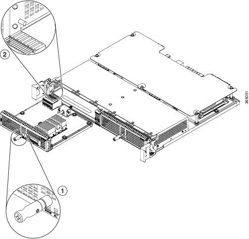
Figure 4-2 MIP Installation and Removal
|
|
|
Checking the Installation
This section describes the procedures you can use to verify the MIP and EPA installation, and includes information on the following topics:
- Verifying the Installation
- Using show Commands to Verify the MIP and EPA Status
- Using show Commands to Display EPA Information
Verifying the Installation
This section describes how to verify the MIP and EPA installation by observing the MIP LED states, EPA LED states, and the information displayed on the console terminal.
When the system has reinitialized all interfaces, the MIP STATUS LED should be green (on) and the EPA STATUS LEDs should be green (on). The port LEDs may be green (on), depending on your connections and configuration. The console screen also displays a message as the system discovers each interface during reinitialization.
Use the following procedure to verify that a MIP and EPA are installed correctly:
Step 1![]() Observe the console display messages and verify that the system discovers the MIP, while the system reinitializes each interface, as follows:
Observe the console display messages and verify that the system discovers the MIP, while the system reinitializes each interface, as follows:
- When a new EPA is inserted into the system, the default configuration will be used for the associated interfaces.
- As a MIP is initialized, the STATUS LED will first be amber, indicating that power is on, but the MIP is being configured. When the MIP is active, the STATUS LED will illuminate green.
- EPAs will follow the same sequence once the MIP has completed its initialization. The EPA STATUS LEDs will illuminate amber, turning to green when the EPAs become active.
- When the MIP and EPA STATUS LEDs are green, all associated interfaces are configurable.
Note![]() Refer to the Cisco ASR 1000 Series Modular Ethernet Line Card Software Configuration Guide for configuration instructions.
Refer to the Cisco ASR 1000 Series Modular Ethernet Line Card Software Configuration Guide for configuration instructions.
- If a MIP or EPA is replaced with a module of the same type (as in an OIR or hardware swap), the previous configuration will be reinstated when the MIP or EPA becomes active.
- If a MIP or EPA has not been previously installed in the same slot or subslot, then the configuration for all associated interfaces will be empty.
Note![]() New interfaces are not available until you configure them.
New interfaces are not available until you configure them.
Step 2![]() If the MIPs and EPAs have not become active within three minutes, refer to the system console messages as follows:
If the MIPs and EPAs have not become active within three minutes, refer to the system console messages as follows:
- If a MIP or EPA is undergoing a field-programmable device (FPD) upgrade, then console messages will indicate that the FPD process has been initiated. The upgrade process might take several minutes. Use the show upgrade fpd progress command to obtain information about the FPD process. MIPs or EPAs that undergo an FPD upgrade will automatically be rebooted. Return to Step 1.
- If there is no indication that an FPD upgrade is under way, see Chapter6, “Troubleshooting”
Using show Commands to Verify the MIP and EPA Status
The following procedure uses show commands to verify that the new EPAs are configured and operating correctly.
Step 1![]() Use the show running-config command to display the system configuration. Verify that the configuration includes the new EPA interfaces.
Use the show running-config command to display the system configuration. Verify that the configuration includes the new EPA interfaces.
Step 2![]() Display all of the current EPAs and a summary of their status using the show hw-module subslot all oir command.
Display all of the current EPAs and a summary of their status using the show hw-module subslot all oir command.
Step 3![]() Display information about the installed MIPs using the show diag command.
Display information about the installed MIPs using the show diag command.
Step 4![]() Use the show hw-module subslot all fpd command to verify the FPD version information of the EPAs installed in the system.
Use the show hw-module subslot all fpd command to verify the FPD version information of the EPAs installed in the system.
Note![]() If an EPA does not meet the minimum FPD version required, it will be updated automatically. If the update fails, the failing EPA will be powered down and an error message will be reported on the system console.
If an EPA does not meet the minimum FPD version required, it will be updated automatically. If the update fails, the failing EPA will be powered down and an error message will be reported on the system console.
For more information about FPD upgrades, refer to the “Upgrading Field-Programmable Devices” chapter of the Cisco ASR 1000 Series Modular Ethernet Line Card Software Configuration Guide.
Step 5![]() Use the show version command to obtain a few details on the installed MIPs and interfaces.
Use the show version command to obtain a few details on the installed MIPs and interfaces.
Using show Commands to Display EPA Information
Table 4-1 describes the show commands you can use to display EPA information.
The following example shows the output of the show diag subslot slot / subslot eeprom detail command for an EPA located in slot 3, subslot 1:
EPA Blank Filler Plates
EPA blank filler plates (EPA-BLANK=) are available to fill an unused EPA subslot.
When an EPA subslot is not in use, an EPA blank filler plate must be installed in the empty subslot to allow the router or switch to conform to electromagnetic interference (EMI) emissions requirements and to allow proper airflow across the EPAs. If you plan to install a new EPA in a subslot that is not in use, you must first remove the EPA blank filler plate.
 Feedback