Installing and Removing a MIP
This chapter describes how to install and remove a MIP on the Cisco ASR 1000 Series Aggregation Services Routers. This chapter contains the following sections:
Handling the MIP
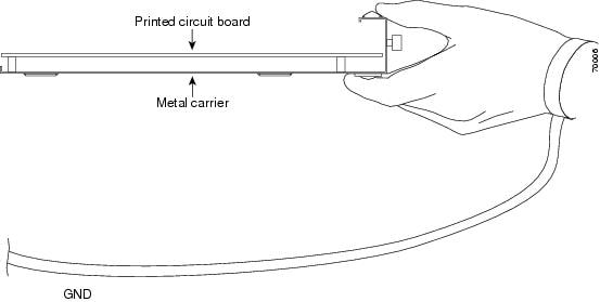
Each MIP circuit board is mounted on a metal carrier and is sensitive to electrostatic discharge (ESD) damage. Before you begin installation, read Chapter 2, “Preparing to Install a MIP or EPA” for a list of parts and tools required for installation.

When a slot is not in use, a blank filler plate must be installed in the empty slot to allow the router or switch to conform to electromagnetic interference (EMI) emission requirements and to allow proper airflow across the installed modules. If you plan to install the MIP in a slot that is not in use, you must first remove the blank filler plate.
Online Insertion and Removal
The Cisco ASR 1000 Series Aggregation Services Routers support online insertion and removal (OIR) of the MIP, the EPAs, and the SFP+ and CPAK modules. Therefore, you can remove the MIP with its SFP+ or CPAK modules still intact, or you can remove SFP+ or CPAK modules independently from the MIP, leaving the line card installed in the router.
This section includes the following topics on OIR support:
- Preparing for Online Removal of the MIP
- Deactivating a MIP
- Reactivating a MIP
- Verifying the Deactivation and Activation of the MIP
Preparing for Online Removal of the MIP
The Cisco ASR 1000 series router support OIR of the MIP. If you plan to remove a MIP, deactivate the line card first using the hw-module slot slotnumber shutdown global configuration command.
When you deactivate the MIP using this command, it automatically deactivates each of the SFP+ or CPAK modules that are installed in the MIP. Therefore, it is not necessary to deactivate each of the SFP+ or CPAK modules prior to deactivating the MIP.
Although graceful deactivation of the MIP is preferred using the hw-module slot slotnumber shutdown command, the Cisco ASR 1000 series router do support the removal of the MIP without deactivating it first.
Deactivating a MIP
To deactivate a MIP and its installed SFP+ or CPAK modules prior to the removal of the MIP, use the following command in the global configuration mode:
Reactivating a MIP
After you deactivate the MIP, whether or not you have performed an OIR, you must use the no hw-module slot slotnumber shutdown global configuration command to reactivate the MIP.
The installed SFP+ or CPAK modules automatically get reactivated upon reactivation of the MIP in the router. For example, consider a scenario where you remove a MIP from the router to replace it with another MIP. You reinsert the same EPAs and SFP+ or CPAK modules into the new MIP. When you enter the no hw-module slot slotnumber shutdown command on the router, the SFP+ or CPAK modules will automatically get reactivated with the new MIP.
To reactivate a MIP and its installed SFP+ or CPAK modules after the MIP has been deactivated, use the following command in the global configuration mode:
Verifying the Deactivation and Activation of the MIP
To verify the deactivation of the MIP, enter the show platform command in the privileged EXEC configuration mode. Observe the State field associated with the MIP that you want to verify.
The following example shows the MIP located in slot 1. In this scenario, slot 1 is powered down. This is indicated by its disabled status.
To verify the activation and proper operation of a MIP, enter the no hw-module slot 1 shutdown command. After this, enter the show platform command and observe slot 1 in the ok state. Finally, enter the show platform diag command and observe ok in the Running state field, as shown in the following example:
MIP Installation and Removal
This section provides step-by-step instructions for installing and removing a MIP.
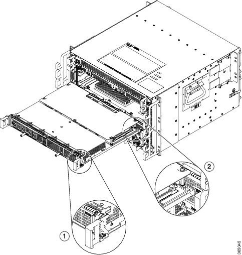
To install a MIP, refer to Figure 3-2 and do the following:
Step 1![]() Before inserting a MIP, make sure that the chassis is grounded.
Before inserting a MIP, make sure that the chassis is grounded.
Step 2![]() To insert the MIP, carefully align the edges of the MIP between the guide rails in the router slot.
To insert the MIP, carefully align the edges of the MIP between the guide rails in the router slot.
Step 3![]() Carefully slide the MIP into the router slot until the MIP makes contact with the backplane.
Carefully slide the MIP into the router slot until the MIP makes contact with the backplane.
Step 4![]() Tighten the captive installation screws on both sides of the MIP.
Tighten the captive installation screws on both sides of the MIP.
To remove a MIP, refer to Figure 3-2 and do the following:
Step 1![]() To remove the MIP, first disconnect all cables from the SPF+ or CPAK interfaces.
To remove the MIP, first disconnect all cables from the SPF+ or CPAK interfaces.
Step 2![]() Loosen the captive installation screws on both sides of the MIP.
Loosen the captive installation screws on both sides of the MIP.
Step 3![]() Slide the MIP out of the router slot.
Slide the MIP out of the router slot.
Figure 3-2 MIP Installation and Removal
|
|
|
 Feedback