Cisco 4G LTE on the IR8140H
Cisco LTE Pluggable Modules operate over Fourth-Generation Long-Term Evolution (4G LTE) cellular networks and Third-Generation (3G) cellular networks.
The IR8140H offers LTE support through the use of Pluggable Modules. You can find a list of the supported Pluggable Modules in the IR8100H Industrial Integrated Services Router Hardware Installation Guide.
The Cisco LTE Pluggable Module supports the following 4G/3G modes:
-
4G LTE —4G LTE mobile specification provides multi-megabit bandwidth, more efficient radio network, latency reduction, and improved mobility. LTE solutions target new cellular networks. These networks initially support up to 100 Mb/s peak rates in the downlink and up to 50 Mb/s peak rates in the uplink. The throughput of these networks is higher than the existing 3G networks
-
3G Evolution High-Speed Packet Access (HSPA/HSPA+) —HSPA is a UMTS-based 3G network. It supports High-Speed Downlink Packet Access (HSDPA) and High-Speed Uplink Packet Access (HSUPA) data for improved download and upload speeds. Evolution High-Speed Packet Access (HSPA+) supports Multiple Input/Multiple Output (MIMO) antenna capability.
-
3G Evolution-Data Optimized (EVDO or DOrA) Mode —EVDO is a 3G telecommunications standard for the wireless transmission of data through radio signals, typically for broadband Internet access. DOrA refers to EVDO Rev-A. EVDO uses multiplexing techniques including Code Division Multiple Access (CDMA), as well as Time Division Multiple Access (TDMA), to maximize both individual users' throughput and the overall system throughput.
It is important to understand the architecture of the IR8140H series and the relationship between Modems, SIMs, Interface and Controller. The following table helps to illustrate these relationships.
|
Router |
Controller |
SIM |
Modem SubSlot |
PDN Interface |
Line |
|---|---|---|---|---|---|
|
IR8140H |
0/2/0 |
0|1 |
0/1 |
Cellular 0/2/0 Cellular 0/2/1 |
N/A |
|
0/3/0 |
0|1 |
0/1 |
Cellular 0/3/0 Cellular 0/3/1 |
N/A |
For information on supported antennas and accessories, see the Cisco Industrial Routers and Industrial Wireless Access Points Antenna Guide https://www.cisco.com/c/en/us/td/docs/routers/connectedgrid/antennas/installing-combined/industrial-routers-and-industrial-wireless-antenna-guide.html.
For more information on Cisco 4G LTE Advanced SKUs, faceplates, and LED descriptions, see the Cisco IR8140H Series Hardware Installation Guide.
Prerequisites for Configuring Cisco 4G LTE Advanced
-
If the signal is not good at the router, use the Cisco offered antenna accessories and extension cables to place the antenna away from router in a better coverage area. Please refer to the RSSI/SNT values as displayed through show cellular 0/2/0 all or the LED of the pluggable modem.
-
You must have 4G LTE network coverage where your router is physically placed. For a complete list of supported carriers.
-
You must subscribe to a service plan with a wireless service provider and obtain a Subscriber Identity Module (SIM) card. Only micro SIM is supported.
-
You must install the SIM card before configuring the 4G LTE or router.
-
The standalone antenna that supports GPS capabilities must be installed for the GPS feature to work.
Restrictions for Configuring Cisco 4G LTE Advanced
-
Currently, cellular networks support only user initiated bearer establishment.
-
Due to the shared nature of wireless communications, the experienced throughput varies depending on the number of active users or congestion in a given network.
-
Cellular bandwidth is asymmetric with the downlink data rate being greater than the uplink data rate.
-
Cellular networks have higher latency compared to wired networks. Latency rates depend on the technology and carrier. Latency also depends on the signal conditions and can be higher because of network congestion.
-
CDMA-EVDO, CDMA-1xRTT, and GPRS technology modes are not supported.
-
Any restrictions that are part of the terms of service from your carrier.
-
SMS—Only one text message up to 160 characters to one recipient at a time is supported. Larger texts are automatically truncated to the proper size before being sent.
-
It is strongly recommended that you configure SNMP V3 with authentication/privacy.
Features not Supported in 4G LTE Advanced
The following features are not supported on Cisco 4G LTE Advanced on the IR8100, when compared to Classic IOS:
-
TTY support or Line
-
Chat script/dialer string
-
DM log output to USB flash is not supported.
Cisco 4G LTE-Advanced Features
Cisco 4G LTE-Advanced supports the following major features:
-
Short Message Service (SMS)
-
SMS on dying gasp available on the IRMH-LTEA-EA, IRMH-LTEA-LA, IRMH-LTE-MNA, and IRMH-LTEAP18-GL.
-
3G/4G Simple Network Management Protocol (SNMP) MIB
-
SIM lock and unlock capabilities
-
Dual SIM
-
Auto SIM
-
NeMo
-
Mobile Network IPv6
-
Public Land Mobile Network (PLMN) selection
-
IPv6
-
Multiple PDN
-
LTE Link Recovery
Dual SIM Card
 Note |
The P-LTE-VZ pluggable which supports Verizon is a single SIM. |
controller cellular 0/2/0
lte sim primary slot <slot#>
If the active SIM card loses connectivity to the network a failover to the alternative SIM card slot occurs.
By default the failover timer is 3 minutes. The failover timer can be set from 3 to 7 minutes.
controller cellular 0/2/0
lte failovertimer <3-7>
You can also manually switch the SIM slot via the command line interface.
cellular 0/2/0 lte sim activate slot <0-1>Auto SIM
The Auto SIM feature detects the SIM and loads the corresponding firmware. For example, if an AT&T SIM is detected, the modem loads the AT&T firmware.
When Auto-SIM is enabled, it is said to be in Auto-SIM mode and when disabled, it is known as Manual mode. In Auto-SIM mode, the modem selects the right carrier firmware from the list of firmware's available. When in manual mode, you can select the firmware manually. Modem resets every time you make a config change from Auto-SIM enabled to disabled or vice-versa.
Cisco cellular modules support the AUTO-SIM feature only for certain cellular carriers for which the modem carrier firmware is available on the Cisco CCO website. Other carriers, whose firmware is not available for the module, must use GENERIC firmware along with manually configured profiles with appropriate Access Point Names (APNs) as specified by the carriers.
Note |
Auto SIM is always enabled by default. |
Enable Auto SIM
Procedure
| Command or Action | Purpose | |||
|---|---|---|---|---|
| Step 1 |
configure terminal Example: |
Enters configuration mode. |
||
| Step 2 |
controller cellular 0/2/0 |
|||
| Step 3 |
cellular slot/ sub-slot/ interface firmware auto-sim Example: |
Enables Auto-SIM feature if previously disabled.
|
Example: List the firmware when Auto-SIM is Enabled
Device# show cellular 0/2/0 firmware
Idx Carrier FwVersion PriVersion Status
1 ATT 02.37.00.00 002.098_000 Inactive
2 VERIZON 02.37.03.00 002.104_000 Active

Firmware Activation mode  =  AUTO
Device# show cellular 0/2/0
Idx Carrier FwVersion PriVersion Status
1 ATT 02.37.00.00 002.098_000 Inactive
2 GENERIC 02.37.03.00 002.095_000 Inactive
3 KDDI 02.37.03.00 001.048_000 Inactive
4 SOFTBANK 02.37.03.00 001.050_000 Inactive
5 TELUS 02.37.03.00 001.017_000 Inactive
6 VERIZON 02.37.03.00 002.104_000 Inactive
7 VODAFONE 02.37.03.00 000.011_000 Inactive

Firmware Activation mode  =  AUTO
Disable Auto SIM
Procedure
| Command or Action | Purpose | |
|---|---|---|
| Step 1 |
configure terminal Example: |
Enters configuration mode. |
| Step 2 |
controller cellular slots/ sub-slots/ interface Example: |
Specifies the controller interface. |
| Step 3 |
no lte firmware auto-sim Example: |
Disable auto SIM. |
Example: List the firmware when Auto-SIM is Disabled
Device# show cellular 0/2/0 firmware
Idx Carrier FwVersion PriVersion Status
1 ATT 02.37.00.00 002.098_000 Inactive
2 GENERIC 02.37.03.00 002.095_000 Active
3 KDDI 02.37.03.00 001.048_000 Inactive
4 SOFTBANK 02.37.03.00 001.050_000 Inactive
5 TELUS 02.37.03.00 001.017_000 Inactive
6 VERIZON 02.37.03.00 002.104_000 Inactive
7 VODAFONE 02.37.03.00 000.011_000 Inactive

Firmware Activation mode  =  Manual
Using a SIM Card
Cisco 4G LTE-Advanced needs an active SIM card provided by a service provider. The SIM cards are usually provided in an unlocked state so that it can be used without a Personal Identification Number (PIN). If the SIM is unlocked, it can be inserted into a 4G LTE-Advanced and used without an authorization code.
The SIM can be initially locked with a PIN code (4 to 8 digits s long) defined by the service provider. Contact your service provider for the PIN code.
The SIM-Lock feature allows a SIM to be locked or unlocked with a PIN code so that it is used only in an authorized device. Perform the SIM lock and unlock procedures using the Cisco IOS CLI through a console or Telnet/SSH to the ISR.
After the SIM is locked, it cannot initiate a call unless authentication is done using the same PIN. Authentication is done automatically by Cisco IOS through configuration of the PIN. This mandatory configuration for automatic SIM authentication is done using the Cisco IOS CLI as part of the router startup configuration.
After the Cisco IOS configuration is in place, the ISR can initiate an LTE connection. The ISR uses the configured PIN to authenticate prior to the LTE connection. If the Cisco IOS PIN configuration is missing or if the PIN is incorrect, the SIM authentication will fail and the connection will not be initiated.
If the locked SIM is moved to a different ISR or to another device, or if the 4G LTE-Advanced in which the locked SIM resides is moved to a different 4G LTE-Advanced slot in the same ISR, the ISR configuration should be changed. The configuration is associated with the cellular controller that is specific to an ISR 4G LTE-Advanced slot number. This will ensure that the SIM card will not be used in any unauthorized device, or, if there are multiple 4G LTE-Advanced in a single ISR, that the appropriate PIN is applied to each 4G LTE-Advanced SIM. An authentication command (with the same PIN used to lock the SIM) must be defined on the new device or on the new cellular controller slot to successfully initiate the LTE connection.
The following procedures are used to configure a SIM:
 Caution |
It is very important to use the correct PIN after it is configured. The SIM card will be blocked if the wrong PIN is entered three consecutive times on a locked SIM during authentication or when trying to unlock a locked SIM. You can unblock a blocked SIM card using the PUK code. Contact your service provider for the PUK code. Use the cellular <slot> lte sim unblock <PUK code> <new PIN code> command to unblock the SIM. |
Changing the PIN
Ensure that you enter the correct PIN. The SIM card gets blocked if the wrong PIN is entered three consecutive times.
Procedure
| Command or Action | Purpose | ||||
|---|---|---|---|---|---|
|
cellular interface lte sim change-pin current-pin new-pin Example: |
Locks or unlocks the SIM card using a PIN code.
|
Locking and Unlocking a SIM Card Using a PIN
Perform this task to lock or unlock a SIM card given by your service provider. Make sure you enter the correct PIN, the SIM card gets blocked if the wrong PIN is entered three consecutive times.
Procedure
| Command or Action | Purpose | ||
|---|---|---|---|
|
cellular slot lte sim {lock | unlock } pin Example: |
Locks or unlocks the SIM card using a PIN code.
|
Configure CHV1 for Unencrypted Levels
Use either of these commands:lte sim authenticate 0 pin
or lte sim authenticate 0 pin slot {0 | 1}Procedure
| Command or Action | Purpose |
|---|---|
|
controller cellular interface Example: |
Enters the cellular controller configuration mode or |
Configure CHV1 for Unencrypted Level7
To configure an encrypted PIN, the scrambled value of the PIN must be obtained. To get the scrambled Level 7 PIN and to configure the SIM CHV1 code for verification using this encrypted PIN, enter the following commands in the EXEC mode. When obtaining the encrypted PIN for a SIM, a username and password are created by configuring password encryption, defining the username and associated password, copying the resulting scrambled password, and using this scrambled password in the SIM authentication command.
Note |
After the scrambled PIN has been obtained and used in SIM authentication, the username created can be deleted from the Cisco IOS configuration. A SIM should be locked for SIM authentication to work |
Procedure
| Command or Action | Purpose | |||
|---|---|---|---|---|
| Step 1 |
service password-encryption Example: |
Enables password encryption. |
||
| Step 2 |
username privilege var password pin Example: |
|
||
| Step 3 |
do show run | i name Example: |
Shows the username configuration line with the encrypted level 7 PIN for the username created in Step 3 (user “SIM” in the example shown). Copy the scrambled password for use in Step 6 (as the PIN). |
||
| Step 4 |
username privilege 0 password pin Example: |
Enters the cellular controller configuration mode. |
||
| Step 5 |
lte sim authenticate 7 pin OR lte sim authenticate 7 pin slot {0 | 1} Example: |
Authenticates the SIM CHV1 code by using the encrypted keyword 7 and the scrambled PIN from Step 4. The PIN is sent to the modem for authentication with each subsequent LTE connection. If authentication passes based on the configured PIN, the data call is allowed. If authentication fails, the modem does not initiate the data call.
|
||
| Step 6 |
exit Example: |
(Optional) Exits the cellular controller configuration mode. |
||
| Step 7 |
no usernamename Example: |
(Optional) Removes the username and password created in Step 3 |
||
| Step 8 |
no service password-encryptionname Example: |
(Optional) Removes the username and password created in Step 3 |
Short Message Service (SMS) Capabilities
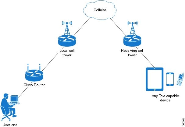
Cisco 4G LTE-Advanced support receiving, transmitting, archiving, and deleting of SMS messages. This support includes the ability to view up to 25 received texts, and archive more messages in a custom file location. SMS is supported on multiple carriers. Cisco 4G LTE-Advanced also have the capability to revert from LTE SMS to 3G technology if necessary.
A sending device behind a Cisco 4G LTE-Advanced transmits an SMS text message over the 4G cellular link through cellular towers until it the message reaches the recipient’s router, which then notifies the recipient device, such as a cell phone. The receiving device uses the same process to return a reply to the sending device. The following figure describes the flow from a mobile device to a sending device. For SMS transmission to work, end users must have a text-capable device, and optionally, a text plan. If end users do not have a text plan, standard SMS rates apply to their text transmissions.
Data Account Provisioning
One or more modem data profiles can be created to provision a modem on a 4G LTE SKU. An active wireless account with a service provider with one or more (dual) SIM cards must be installed. The modem data profile is pre-configured on the modem.
The following tasks are used to verify the signal strength and service availability of the modem and to create, modify, and delete modem data profiles:
IP Multimedia Subsystem Profiles
IP Multimedia Subsystem (IMS) profiles establish a session, and are a part of the modem configuration and are stored in the modem's NVRAM. An IMS network is an access-independent and standard-based IP connectivity service that enables different types of multimedia services to end users using common Internet-based protocols.
Configuring Cisco 4G LTE Advanced
For 4G-LTE-Advanced, the numbering on the IR8100 for slot, module, and port is:
-
cellular 0/2/0
-
cellular 0/2/1
-
cellular 0/3/0
-
cellular 0/3/1
Verifying Modem Signal Strength and Service Availability
For the 4G LTE Advanced, the slot argument identifies the router slot, module slot, and port separated by slashes (0/2/0).
Procedure
| Command or Action | Purpose | |||
|---|---|---|---|---|
| Step 1 |
show cellular slot network Example: |
Displays information about the carrier network, cell site, and available service. |
||
| Step 2 |
show cellular slot radio Example: |
Shows the radio signal strength.
|
||
| Step 3 |
show cellular slot profile Example: |
Shows information about the modem data profiles created. |
||
| Step 4 |
show cellular slot security Example: |
Shows the security information for the modem, such as SIM and modem lock status. |
||
| Step 5 |
show cellular slot all Example: |
Shows consolidated information about the modem, profiles created, radio signal strength, network security, and so on. |
Guidelines for Creating, Modifying, or Deleting Modem Data Profiles
Customized profiles (Access Point Name (APN) in mobile networks) can be created and used on Cisco 4G LTE Advanced SKUs. The maximum number of profiles that can be created is 16.
For Cisco SKUs shipping with a specific carrier provisioning file (which can be found in Carrier label under "show cellular <slot> hardware"), default profiles are already populated and can be deployed readily.
In all other cases where profile configurations are not available, separate profiles should be created with required parameters.
All the PIDs supported for IR8140H can support the default profile as Internet for Profile 1. In addition, PIDs IRMH-LTEA-EA, IRMH-LTE-MNA, and IRMH-LTEAP18-GL support Verizon for both Profile 1 and Profile 3.
Follow these guidelines when you configure a data profile using EXEC mode or Config mode:
-
You do not have to make any profile-related changes if your modem comes with a data profile, for instance, AT&T, Sprint and Verizon.
-
If any profile parameter changes are required for a connection type, the changes will likely be carried out in the default profiles.
-
To configure different profile types and use them for a different connection, you can create separate profiles with different parameters (for instance, APN names). Note that only one profile is active at a given time.
-
Use the show cellular <slot> profile command to view the data profile. An asterisk(*) symbol is displayed against the data profile. Double asterisk(**) symbol is displayed against the attach profile.
-
The data profile is used to set up a data call. If you want to use a different profile, that profile needs to be made the default one. Use the lte sim data-profile number command to change the default profile under controller cellular 0/2/0 .
Creating, Modifying, or Deleting Data Profiles Using EXEC Mode
Customized profiles (Access Point Name (APN) in mobile networks) can be created and used on Cisco 4G LTE Advanced SKUs. Maximum number of profiles that can be created are 16.
Cisco SKU's shipping with specific carrier provisioning file (can be found in carrier label under show cellular slot hardware , default profiles are already populated and can be deployed readily.
Note |
For the 4G LTE Advanced, the slot argument identifies the router slot, module slot, and port separated by slashes (0/2/0). |
Procedure
| Command or Action | Purpose | ||
|---|---|---|---|
|
cellular slot lte profile [ create | delete ] profile-number [ apn [ authentication [ username password [ bearer-type]]]] Example: |
Creates, modifies, or deletes a modem data profile in the privileged EXEC mode.
The show cellular slot profile displays configured profile list.
|
Example
router# show cellular 0/2/0 profile
Profile 1 = INACTIVE **
--------
PDP Type = IPv4v6
Access Point Name (APN) = vzwims
Authentication = None

Profile 2 = INACTIVE
--------
PDP Type = IPv4v6
Access Point Name (APN) = vzwadmin
Authentication = None

Profile 3 = ACTIVE*
--------
PDP Type = IPv4v6
PDP address = 100.119.136.44
PDP IPV6 address = 2600:1010:B00E:1E11:192D:3E20:199B:3A70/64  Scope: Global
Access Point Name (APN) = VZWINTERNET
Authentication = None
        Primary DNS address = 198.224.173.135
        Secondary DNS address = 198.224.174.135
        Primary DNS IPV6 address = 2001:4888:68:FF00:608:D:0:0
        Secondary DNS IPV6 address = 2001:4888:61:FF00:604:D:0:0

Profile 4 = INACTIVE
--------
PDP Type = IPv4v6
Access Point Name (APN) = vzwapp
Authentication = None

Profile 5 = INACTIVE
--------
PDP Type = IPv4v6
Access Point Name (APN) = vzw800
Authentication = None

Profile 6 = INACTIVE
--------
PDP Type = IPv4v6
Access Point Name (APN) = CISCO.GW4.VZWENTP
Authentication = None

  * - Default profile
 ** - LTE attach profile
#show cellular 0/3/0 profile
Profile 1 = INACTIVE **
--------
PDP Type = IPv4v6
Access Point Name (APN) = vzwims
Authentication = None

Profile 2 = INACTIVE
--------
PDP Type = IPv4v6
Access Point Name (APN) = vzwadmin
Authentication = None

Profile 3 = ACTIVE*
--------
PDP Type = IPv4v6
PDP address = 100.86.69.19
PDP IPV6 address = 2600:1010:B040:DA58:1C27:D97:321E:18C4/64  Scope: Global
Access Point Name (APN) = VZWINTERNET
Authentication = None
	Primary DNS address = 198.224.173.135
	Secondary DNS address = 198.224.174.135
	Primary DNS IPV6 address = 2001:4888:68:FF00:608:D:0:0
	Secondary DNS IPV6 address = 2001:4888:61:FF00:604:D:0:0

Profile 4 = INACTIVE
--------
PDP Type = IPv4v6
Access Point Name (APN) = vzwapp
Authentication = None

Profile 5 = INACTIVE
--------
PDP Type = IPv4v6
Access Point Name (APN) = vzw800
Authentication = None

Profile 6 = INACTIVE
--------
PDP Type = IPv4v6
Access Point Name (APN) = vzwclass6
Authentication = None

  * - Default profile
 ** - LTE attach profile


Configured default profile for active SIM 0 is profile 3.
Note |
If data and attach profile bindings need modification, use the controller cellular slot. |
router(config-controller)# lte sim data-profile 3 attach-profile 2 slot slot
Device#show cellular 0/2/0 profile
Profile 1 = INACTIVE
--------------------------------------------------
PDP Type = IPv4v6
Access Point Name (APN) = test
Authentication = None

Profile 2 = INACTIVE **
--------
PDP Type = IPv4
Access Point Name (APN) = internet
Authentication = PAP or CHAP
Username =  user@solution.com
Password =  cisco

Profile 3 = INACTIVE*
--------
PDP Type = IPv4v6
Access Point Name (APN) = basic
Authentication = None

  * - Default profile
 ** - LTE attach profile
Configured default profile for active SIM 0 is profile 2.
Configuration Examples
The following example shows how to change a default profile on 4G LTE Advanced:
router(config-controller)# lte sim data-profile 2 attach-profile 1 slot slot
The following example shows the output of the show cellular command for Verizon network service:
router# show cellular 0/2/0 profile
Profile 1 = INACTIVE **
--------
PDP Type = IPv4v6
Access Point Name (APN) = vzwims
Authentication = None

Profile 2 = INACTIVE
--------
PDP Type = IPv4v6
Access Point Name (APN) = vzwadmin
Authentication = None

Profile 3 = ACTIVE*
--------
PDP Type = IPv4v6
PDP address = 100.119.136.44
PDP IPV6 address = 2600:1010:B00E:1E11:192D:3E20:199B:3A70/64  Scope: Global
Access Point Name (APN) = VZWINTERNET
Authentication = None
        Primary DNS address = 198.224.173.135
        Secondary DNS address = 198.224.174.135
        Primary DNS IPV6 address = 2001:4888:68:FF00:608:D:0:0
        Secondary DNS IPV6 address = 2001:4888:61:FF00:604:D:0:0

Profile 4 = INACTIVE
--------
PDP Type = IPv4v6
Access Point Name (APN) = vzwapp
Authentication = None

Profile 5 = INACTIVE
--------
PDP Type = IPv4v6
Access Point Name (APN) = vzw800
Authentication = None

Profile 6 = INACTIVE
--------
PDP Type = IPv4v6
Access Point Name (APN) = CISCO.GW4.VZWENTP
Authentication = None

  * - Default profile
 ** - LTE attach profile
Configuring a SIM for Data Calls
Locking and Unlocking a SIM Card Using a PIN Code
Perform this task to lock or unlock a SIM card given by your service provider.
The SIM card gets blocked if the wrong PIN is entered three consecutive times. Make sure you enter the correct PIN the SIM is configured with. If your SIM card gets blocked, contact your service provider for a PUK code. Using the PUK code, you can unblock the SIM card.
For the 4G LTE Advanced, the slot argument identifies the router slot, module slot, and port separated by slashes (0/2/0).
Procedure
| Command or Action | Purpose |
|---|---|
|
cellular slot lte sim {lock | unlock } pin Example: |
Locks or unlocks the SIM card using a PIN code.
|
Changing the PIN Code
Perform this task to change the PIN code of a SIM.
For the 4G LTE Advanced, the slot argument identifies the router slot, module slot, and port separated by slashes (0/2/0).
Procedure
| Command or Action | Purpose |
|---|---|
|
cellular slot lte sim change-pin pin new-pin Example: |
Changes the assigned PIN code. SIM should be in locked state when the PIN is being changed. |
Verifying the Security Information of a Modem
Perform this task to verify the security information of a modem.
Note |
For the 4G LTE Advanced, the slot argument identifies the router slot, module slot, and port separated by slashes (0/2/0). |
Procedure
| Command or Action | Purpose |
|---|---|
|
show cellular slot security Example: |
Shows the security information of the modem, including the SIM lock status. |
Configuring Automatic Authentication for a Locked SIM
An unencrypted PIN can be configured to activate the Card Holder Verification (CHV1) code that authenticates a modem.
The SIM card gets blocked if the wrong PIN is entered three consecutive times. Make sure you enter the correct PIN the SIM is configured with. If your SIM card gets blocked, contact your service provider for a PUK code.
Follow these procedures when using an unencrypted Level 0 PIN to configure CHV1. For instructions on how to configure CHV1 using an encrypted Level 7 PIN, see the Configuring an Encrypted PIN for a SIM.
A SIM should be locked for SIM authentication to work. To verify the SIM’s status, use the show cellular slot security command.
For the 4G LTE Advanced, the slot argument identifies the router slot, module slot, and port separated by slashes (0/2/0).
Procedure
| Command or Action | Purpose | |||
|---|---|---|---|---|
| Step 1 |
configure terminal Example: |
Enters global configuration mode. |
||
| Step 2 |
controller cellular slot Example: |
Enters the cellular controller configuration mode. |
||
| Step 3 |
lte sim authenticate 0 pin |
Authenticates the SIM CHV1 code by using an unencrypted (0 ) keyword and PIN. This PIN is sent to the modem for authentication with each subsequent LTE connection. If authentication passes based on the configured PIN, the data call is allowed. If authentication fails, the modem does not initiate the data call.
|
Configuring an Encrypted PIN for a SIM
To configure an encrypted PIN, the scrambled value of the PIN must be obtained. To get the scrambled Level 7 PIN and to configure the SIM CHV1 code for verification using this encrypted PIN, enter the following commands in the EXEC mode.
Note |
When obtaining the encrypted PIN for a SIM, a username and password are created by configuring password encryption, defining the username and associated password, copying the resulting scrambled password, and using this scrambled password in the SIM authentication command. After the scrambled PIN has been obtained and used in SIM authentication, the username created can be deleted from the Cisco IOS configuration. |
Note |
A SIM should be locked for SIM authentication to work. To verify the SIM’s status, use the show cellular <slot> security command. |
Note |
For the 4G LTE SKU, the slot argument identifies the router slot, module slot, and port separated by slashes (0/2/0). |
Procedure
| Command or Action | Purpose | |
|---|---|---|
| Step 1 |
configure terminal Example: |
Enters global configuration mode. |
| Step 2 |
service password-encryption Example: |
Enables password encryption. |
| Step 3 |
username name privilege 0 password pin Example: |
Creates username and password.
|
| Step 4 |
do show run | i name Example: |
Shows the username configuration line with the encrypted level 7 PIN for the username created in Step 3 (user “SIM” in the example shown). Copy the scrambled password for use in Step 6 (as the PIN). |
| Step 5 |
controller cellular slot Example: |
Enters the cellular controller configuration mode. |
| Step 6 |
lte sim authenticate {0 | 7 } pin |
Authenticates the SIM CHV1 code by using the encrypted keyword 7 and the scrambled PIN from Step 4. The PIN is sent to the modem for authentication with each subsequent LTE connection. If authentication passes based on the configured PIN, the data call is allowed. If authentication fails, the modem does not initiate the data call. |
| Step 7 |
exit Example: |
(Optional) Exits the cellular controller configuration mode. |
| Step 8 |
no username name Example: |
(Optional) Removes the username and password created in Step 3. |
| Step 9 |
no service password-encryption Example: |
(Optional) Disables password encryption. |
Applying a Modem Profile in a SIM Configuration
Procedure
| Command or Action | Purpose | |
|---|---|---|
| Step 1 |
configure terminal Example: |
Enters the global configuration mode. |
| Step 2 |
controller cellular slot Example: |
Enters the cellular controller configuration mode. |
| Step 3 |
lte sim data-profile data-profile-number attach-profile attach-profile-number slot < 0 | 1 > |
Applies the configured profile number to the SIM and its slot number. The default (primary) slot is 0. The attach profile is the profile used by the modem to attach to the LTE network. The data profile is the profile used to send and receive data over the cellular network. The slot number helps specify different data and attach profiles for two different carrier SIMs. |
Data Call Setup
To set up a data call, use the following procedures:
Configuring the Cellular Interface
To configure the cellular interface, enter the following commands starting in EXEC mode.
For the 4G LTE Advanced, the slot argument identifies the router slot, module slot, and port separated by slashes (0/2/0).
If a tunnel interface is configured with ip unnumbered cellular 0/2/0 , it is necessary to configure the actual static IP address under the cellular interface, in place of ip address negotiated .
Procedure
| Command or Action | Purpose | |||
|---|---|---|---|---|
| Step 1 |
configure terminal Example: |
Enters global configuration mode. |
||
| Step 2 |
interface cellular slot Example: |
Specifies the cellular interface. |
||
| Step 3 |
ip address negotiated Example: |
Specifies that the IP address for a particular interface is dynamically obtained. |
||
| Step 4 |
dialer in-band Example: |
Enables DDR and configures the specified serial interface to use in-band dialing. |
||
| Step 5 |
dialer watch-group group-number Example: |
Specifies the number of the dialer access group to which the specific interface belongs. |
||
| Step 6 |
exit Example: |
Enters the global configuration mode. |
||
| Step 7 |
ip route network-number network-mask {ip-address | interface } [administrative distance ] [name name ] Example: |
Establishes a floating static route with the configured administrative distance through the specified interface.
|
||
| Step 8 |
dialer-list dialer-group protocol protocol-name {permit | deny | list access-list-number | access-group } Example: |
Creates a dialer list for traffic of interest and permits access to an entire protocol. |
Configure Cellular Interface with dialer watch-group
To configure the cellular interface with dialer watch-group, enter the following commands starting in EXEC mode.
Note |
For the 4G LTE Advanced, the slot argument identifies the router slot, module slot, and port separated by slashes (0/2/0). |
Procedure
| Command or Action | Purpose | |
|---|---|---|
| Step 1 |
configure terminal Example: |
Enters global configuration mode. |
| Step 2 |
interface cellular slot Example: |
Specifies the cellular interface. |
| Step 3 |
ip address negotiated Example: |
Specifies that the IP address for a particular interface is dynamically obtained. |
| Step 4 |
dialer in-band Example: |
Enables DDR and configures the specified serial interface to use in-band dialing. |
| Step 5 |
ip address negotiated Example: |
Specifies that the IP address for a particular interface is dynamically obtained. |
| Step 6 |
dialer idle-timeout seconds Example: |
Specifies the duration of idle time, in seconds, after which a line has no outbound traffic. “0” second means no idle timeout. The default idle timeout is 120 seconds if there is no idle timer specified. |
| Step 7 |
dialer watch-group group-number Example: |
Enables Dialer Watch on the specific interface. |
| Step 8 |
exit Example: |
Enters the global configuration mode. |
| Step 9 |
dialer-list dialer-group protocol protocol-name {permit | deny | list access-list-number group-number Example: |
Creates a dialer list for traffic of interest and permits access to an entire protocol. |
| Step 10 |
access-list access-list-number permitip-source-address Example: |
Defines traffic of interest. |
| Step 11 |
dialer watch-list watch-group number ip ip mask Example: |
Defines traffic of interest. |
| Step 12 |
dialer watch-list watch-group numberdelay route-check initial time in seconds Example: |
Defines traffic of interest. |
| Step 13 |
dialer watch-list watch-group number delay connected seconds Example: |
Defines traffic of interest. |
Configuring 4G SMS Messaging
Note |
For an 4G LTE Advanced, the slot argument identifies the router slot, module slot, and the port, and is separated by slashes (0/2/0). |
Procedure
| Command or Action | Purpose | |||
|---|---|---|---|---|
| Step 1 |
configure terminal Example: |
Enters the configuration mode. |
||
| Step 2 |
controller cellular <slot> Example: |
Enters the controller cellular configuration mode. |
||
| Step 3 |
lte sms archive path <FTP-URL> Example: |
Specifies an FTP server folder path to send all the incoming and outgoing SMS messages. After the folder path is identified, it is appended automatically with outbox and inbox folders for the path to which SMS messages are sent and received, for example: |
||
| Step 4 |
cellular slot lte sms view { all | ID | summary } Example: |
Displays the message contents of incoming texts received by a modem.
|
||
| Step 5 |
end Example: |
Exits the configuration mode and returns to the privileged EXEC mode. |
||
| Step 6 |
show cellular slot sms Example: |
Displays all the information in the text messages sent and received. Message information includes text messages sent successfully, received, archived, and messages pending to be sent. LTE-specific information on errors in case of a FAILED attempt may also be displayed. |
||
| Step 7 |
cellular slot lte sms send number SMS_Text Example: |
Enables a user to send a 4G LTE band SMS message to other valid recipients, provided they have a text message plan. The number argument is the telephone number of the SMS message recipient.
|
||
| Step 8 |
cellular slot lte sms delete [ all | id ] Example: |
(Optional) Deletes one message ID or all of the stored messages from memory. |
Configuring Dying Gasp
Pluggable Modules with IRMH-LTEAP18-GL or IRMH-LTEA-EA modems have the capability to supply power to the modem in case of a loss of power to the module to gracefully power off the modem. When a loss of power is detected, the modem is expected to send out Dying gasp SMS when configured.
To configure dying gasp, perform the following:
Procedure
| Command or Action | Purpose | |
|---|---|---|
| Step 1 |
configure terminal Example: |
Enters global configuration mode. |
| Step 2 |
controller cellular <slot> Example: |
Enters interface command mode for the cellular module controller slot. |
| Step 3 |
lte dyinggasp detach enable Example: |
Enables the dying-gasp feature with send detach request. |
| Step 4 |
lte dyinggasp sms send <phone number> <SMS message> Example: |
Configures the phone number to receive SMS text messages and the content of the text message to be sent by the modem when the platform or module is powered down. |
| Step 5 |
exit Example: |
Exits interface configuration mode. |
| Step 6 |
write mem Example: |
Saves the changes to the router configuration. |
Example
The following example shows how to enable the dying-gasp feature on cellular module in slot 0/2/0, specify the phone number receiving the SMS, and the specific SMS text message to be sent by the modem upon power failure.
router# configure terminal
router(config)# controller cellular 0/2/0
router (config-controller)# lte dyinggasp detach enable
router (config-controller)# lte dyinggasp sms send 4081112222 IR8100-#999_IRMH-LTEAP18-GL_powered_off!
Configuring Modem DM Log Collection
Diagnostic Monitor (DM) Log is a modem feature that captures data transactions between the modem and the network over the radio frequency interface. This feature is a useful tool for troubleshooting 3G and 4G data connectivity or performance issues.
Once a DM log file is captured, diagnostic software tools, such as Sierra Wireless SwiLog and Qualcomm QXDM, can be used to decode the DM log file to understand the issues. A member of Cisco TAC can help with decoding the DM log files.
To configure DM log collection, enter the following commands, starting in privileged EXEC mode.
Procedure
| Command or Action | Purpose | |||||||
|---|---|---|---|---|---|---|---|---|
| Step 1 |
configure terminal Example: |
Enters global configuration mode. |
||||||
| Step 2 |
controller cellular slot Example: |
Enters cellular controller configuration mode. |
||||||
| Step 3 |
lte modem dm-log {autoshop { link-down | timer time} | enable | filesize size | filter } bootflash: file | flash: file} rotation | size log-size } Example: |
Configures DM logging for LTE modem.
|
||||||
| Step 4 |
end Example: |
Returns to privileged EXEC mode. |
||||||
| Step 5 |
show cellular slot logs dm-log Example: |
(Optional) Displays DM log configuration and statistics. |
Example
The following example shows how to:
-
Specify the maximum size of all DM log files that can be stored in bootflash or flash to 512 MB.
-
Specify the maximum size of each DM log file to 32 MB.
-
Use MC7xxx_GPS_Log.sqf DM log filter in the flash.
-
Enable rotation.
-
Enable DM log capturing.
Router(config-controller)# controller cell 0/2/0
Router(config-controller)# lte modem dm-log size 512
Router(config-controller)# controller cell 0/2/0
Router(config-controller)# lte modem dm-log filesize 32
The following example shows how to specify the filter file for LTE:
Router(config-controller)# controller cell 0/2/0
Router(config-controller)# lte modem dm-log filter flash:MC7xxx_GPS_Log.sqf
The following example shows how to enable DM log rotation for LTE:
Router(config-controller)# controller cell 0/2/0
Router(config-controller)# lte modem dm-log rotation
The following example shows how to specify the maximum log size for LTE:
Router(config-controller)# controller cell 0/3/0
Router(config-controller)# lte modem dm-log enable
The following example shows how to enable DM log rotation for LTE:
Router(config-controller)# controller cell 0/3/0
Router(config-controller)# end
The following example shows how to specify the maximum log size for LTE:
Router(config-controller)# controller cell 0/3/0
Router(config-controller)# lte modem dm-log size 1024
The following example shows what was configured on the router for DM log feature:
Router#show running-config | section controller
controller Cellular 0/3/0
 lte modem dm-log filter flash:MC7xxx_GPS_Log.sqf
 lte modem dm-log size 512
 lte modem dm-log filesize 32
 lte modem dm-log rotation
 lte modem dm-log enable
 lte modem dm-log size 1024
The following displays DM log configuration and statistics
Router#show cellular 0/3/0 logs dm-log
Integrated DM logging is on
output path = Utility Flash
filter = flash:MC7xxx_GPS_Log.sqf
maximum log size = 536870912
maximum file size = 33554432
log rotation = enabled

32 packets sent to the modem, 3879 bytes, 0 errors
158324 packets received from the modem, 75971279 bytes, 0 input drops
158324 packets stored in utility flash, 75971279 bytes

current file size = 8863042
current log size = 75971279
total log size = 75971279
Utility Flash DM log files =  (3) files
end
The following shows the DM log files created:
Router#dir flash:dmlog*
Directory of bootflash:/dmlog*

Directory of bootflash:/

   27  -rw-    33554069   Jun 7 2020 18:08:46 -08:00  dmlog-slot4-20200921-172930.bin
2885718016 bytes total (521891840 bytes free)
lte modem dm-log size 1024
The following shows hot to disable/stop DM log capturing:
Router(config)#controller cellular 0/3/0
Router(config-controller)#no lte modem dm-log enable
Router(config-controller)#end
Enabling Modem Crashdump Collection
Modem crashdump collection is useful in debugging firmware crash. To collect crash data, the modem has to be pre-configured so that it will stay in memdump mode after a crash. Memdump mode is a special boot-and-hold mode for the memdump utility to collect crash data.
To enable modem crashdump collection, perform the following steps.
Note |
The integrated modem crashdump collection feature is supported only on 3G HSPA and 4G LTE Advanced based SKUs. |
Before you begin
Router#conf t
Enter configuration commands, one per line. End with CNTL/Z.
Router(config)#controller cel 0/2/0
Router(config-controller)#lte modem crash-action ?
boot-and-hold Remain in crash state

Router(config-controller)#lte modem crash-action boot-and-hold
This ensures that whenever the router crashes, it will stay in that state and will not try to recover. By default the crash-action is reset which means the modem will reset and try to recover itself whenever it crashes. The above boot-and-hold command is used to keep the modem in a crashed state so that you can capture crashdump using the following command:
Router#test cell-cwan 0/2/0 modem-crashdump ?
off Disable Modem firmware crash dump
on Enable Modem firmware crash dump

Router#test cell-cwan 0/2/0 modem-crashdump on
This will capture the crashdump and store it in flash.
Procedure
| Command or Action | Purpose |
|---|---|
|
test { cell-cwan } slot modem-crashdump { on location | off } Example: |
Enables or disables modem crashdump collection.
|
Displaying Modem Log Error and Dump Information
As part of the 3G serviceability enhancement, commands strings (at!err and at!gcdump ) can be sent to the modem using Cisco IOS CLI rather than setting up a reverse telnet session to the cellular modem to obtain log error and dump information.
To obtain log error and dump information, perform the following steps.
Note |
The modem log error and dump collection feature is supported only on 3G SKUs. |
Procedure
| Command or Action | Purpose | |
|---|---|---|
| Step 1 |
show cellular slot log error Example: |
Shows modem log error and dump information. |
| Step 2 |
test cellular slot modem-error-clear Example: |
(Optional) Clears out the error and dump registers. By default, error and dump registers are not cleared out after a read. This command changes the operation so that registers are cleared once they are read. As a result, the AT command strings are changed to “at!errclr=–1 ” for CDMA and “at!err=0 ” for GSM modems. |
Verifying the 4G LTE Advanced Router Information
You can verify the configuration by using the following show commands:
show version
Router#show version
Cisco IOS XE Software, Version BLD_V175_THROTTLE_LATEST_20210124_063209_V17_5_0_148
Cisco IOS Software [Bengaluru], ISR Software (ARMV8EL_LINUX_IOSD-UNIVERSALK9_IOT-M), Experimental Version 17.5.20210124:064309 [S2C-build-v175_throttle-507-/nobackup/mcpre/BLD-BLD_V175_THROTTLE_LATEST_20210124_063209 226]
Copyright (c) 1986-2021 by Cisco Systems, Inc.
Compiled Sun 24-Jan-21 06:10 by mcpre


Cisco IOS-XE software, Copyright (c) 2005-2021 by cisco Systems, Inc.
All rights reserved. Certain components of Cisco IOS-XE software are
licensed under the GNU General Public License ("GPL") Version 2.0. The
software code licensed under GPL Version 2.0 is free software that comes
with ABSOLUTELY NO WARRANTY. You can redistribute and/or modify such
GPL code under the terms of GPL Version 2.0. For more details, see the
documentation or "License Notice" file accompanying the IOS-XE software,
or the applicable URL provided on the flyer accompanying the IOS-XE
software.


ROM: 1.4(REL)

CABO_SIT_Cellular uptime is 47 minutes
Uptime for this control processor is 49 minutes
System returned to ROM by reload
System image file is "bootflash:ir8100-universalk9.BLD_V175_THROTTLE_LATEST_20210124_063209_V17_5_0_148.SSA.bin"
Last reload reason: Reload Command


This product contains cryptographic features and is subject to United
States and local country laws governing import, export, transfer and
use. Delivery of Cisco cryptographic products does not imply
third-party authority to import, export, distribute or use encryption.
Importers, exporters, distributors and users are responsible for
compliance with U.S. and local country laws. By using this product you
agree to comply with applicable laws and regulations. If you are unable
to comply with U.S. and local laws, return this product immediately.

A summary of U.S. laws governing Cisco cryptographic products may be found at:
http://www.cisco.com/wwl/export/crypto/tool/stqrg.html

If you require further assistance please contact us by sending email to
export@cisco.com.


Technology Package License Information:

-----------------------------------------------------------------
Technology Type Technology-package Technology-package
Current Next Reboot
-----------------------------------------------------------------
Smart License Perpetual network-advantage network-advantage
Smart License Subscription None None

The current throughput level is 50000 kbps


Smart Licensing Status: Registration Not Applicable/Not Applicable

cisco IR8140H-P-K9 (1RU) processor with 1948753K/6147K bytes of memory.
Processor board ID FDO2441J91D
Router operating mode: Autonomous
2 Gigabit Ethernet interfaces
4 Cellular interfaces
32768K bytes of non-volatile configuration memory.
8116912K bytes of physical memory.
8032254K bytes of Bootflash at bootflash:.

Configuration register is 0x2102
show platform
router# sh platform
Chassis type: IR8140H-P-K9

Slot      Type                State                 Insert time (ago)
--------- ------------------- --------------------- -----------------
0         IR8140H-P-K9        ok                    00:49:21
0/0       IR8140H-2x1GE       ok                    00:48:09
0/1       IRMH-WPAN-NA        ok                    00:48:09
0/2       IRMH-LTEAP18-GL     ok                    00:48:09
0/3       IRMH-LTEA-EA        ok                    00:48:09
1         IRMH-SUP-SP         ok                    00:49:21
R0        IR8140H-P-K9        ok, active            00:49:21
F0        IR8140H-P-K9        ok, active            00:49:21
P0        IRMH-PWR60W-AC      ok                    00:48:43
show interfaces
router#sh interfaces cellular 0/2/0
Cellular0/2/0 is up, line protocol is up
Hardware is LTE pluggable - Global Multimode LTE/LTE-A/DC-HSPA+/HSPA+/HSPA/UMTS/EDGE/GPRS
Internet address is 192.168.5.6/32
MTU 1500 bytes, BW 150000 Kbit/sec, DLY 20000 usec,
reliability 255/255, txload 1/255, rxload 1/255
Encapsulation HDLC, loopback not set
Keepalive not supported
DTR is pulsed for 1 seconds on reset
Last input 00:00:01, output 00:00:01, output hang never
Last clearing of "show interface" counters never
Input queue: 0/375/0/0 (size/max/drops/flushes); Total output drops: 0
Queueing strategy: fifo
Output queue: 0/40 (size/max)
30 second input rate 0 bits/sec, 0 packets/sec
30 second output rate 0 bits/sec, 0 packets/sec
317 packets input, 50359 bytes, 0 no buffer
Received 0 broadcasts (0 IP multicasts)
0 runts, 0 giants, 0 throttles
0 input errors, 0 CRC, 0 frame, 0 overrun, 0 ignored, 0 abort
141 packets output, 20641 bytes, 0 underruns
Output 0 broadcasts (0 IP multicasts)
0 output errors, 0 collisions, 0 interface resets
0 unknown protocol drops
0 output buffer failures, 0 output buffers swapped out
0 carrier transitions

router#
show inventory
router# show inventory
+++++++++++++++++++++++++++++++++++++++++++++++++++++++++++++++++++++++
INFO: Please use "show license UDI" to get serial number for licensing.
+++++++++++++++++++++++++++++++++++++++++++++++++++++++++++++++++++++++

NAME: "Chassis", DESCR: "Cisco Catalyst IR8140H Heavy Duty Series Router with PoE"
PID: IR8140H-P-K9 , VID: V00 , SN: FDO2441J91D

NAME: "Power Supply Module 0", DESCR: "60W AC Power Supply module"
PID: IRMH-PWR60W-AC , VID: V01 , SN: LIT22503LDK

NAME: "module 0", DESCR: "Cisco Catalyst IR8140H-P-K9 Fixed and pluggable Interface Module controller"
PID: IR8140H-P-K9 , VID: , SN:

NAME: "NIM subslot 0/1", DESCR: "IRMH-WPAN-NA Module"
PID: IRMH-WPAN-NA , VID: V00 , SN: FDO24350D18

NAME: "NIM subslot 0/2", DESCR: "IRMH-LTEAP18-GL Module"
PID: IRMH-LTEAP18-GL , VID: V00 , SN: FDO24360MVH

NAME: "Modem on Cellular0/2/0", DESCR: "Telit LM960"
PID: LM960 , VID: 1.0 , SN: 358347100029266

NAME: "PIM subslot 0/2", DESCR: "P-LTEAP18-GL Module"
PID: P-LTEAP18-GL , VID: V01 , SN: FOC242100XW

NAME: "NIM subslot 0/3", DESCR: "IRMH-LTEA-EA Module"
PID: IRMH-LTEA-EA , VID: V00 , SN: FDO24360MU4

NAME: "Modem on Cellular0/3/0", DESCR: "Sierra Wireless EM7455"
PID: EM7455 , VID: 1.0 , SN: 356129072307959

NAME: "PIM subslot 0/3", DESCR: "P-LTEA-EA Module"
PID: P-LTEA-EA , VID: V02 , SN: FOC24290CZ2

NAME: "NIM subslot 0/0", DESCR: "Front Panel 2 port Gigabitethernet Module"
PID: IR8140H-2x1GE , VID: V01 , SN:

NAME: "subslot 0/0 transceiver 1", DESCR: "GE T"
PID: GLC-TE , VID: V03 , SN: AVC24140C5S

NAME: "module 1", DESCR: "Supervisor Module with 1 Copper + 1 Fiber Port for IR8140"
PID: IRMH-SUP-SP , VID: , SN:

NAME: "module 3", DESCR: "Stackable Battery Backup unit for IR8140"
PID: CGR-BATT-4AH , VID: V03 , SN: NVT24231754

NAME: "module 4", DESCR: "Stackable Battery Backup unit for IR8140"
PID: CGR-BATT-4AH , VID: V03 , SN: NVT24233031

NAME: "module 5", DESCR: "Stackable Battery Backup unit for IR8140"
PID: CGR-BATT-4AH , VID: V03 , SN: NVT24232260

NAME: "module R0", DESCR: "Cisco Catalyst IR8140H-P-K9 Route Processor"
PID: IR8140H-P-K9 , VID: V00 , SN: FDO24370MFT

NAME: "module F0", DESCR: "Cisco Catalyst IR8140H-P-K9 Forwarding Processor"
PID: IR8140H-P-K9 , VID: , SN:
Configuring Cellular Modem Link Recovery
The cellular modem link recovery feature is disabled by default and it is recommended to enable the link recovery feature.
Note |
No manual operations or automated scripts interacting with 4G modems may be possible until and unless the modems have come fully in-service. Modems may take approximately 4 minutes after platform bootup and CLI available to be able to allow full interaction and establish IP connectivity. A typical modem power-cycle may also take approximately 4 minutes before any interaction is possible. Modems are in-service after the console displays “%CELLWAN-2-MODEM_RADIO: Cellular0/x/0 Modem radio has been turned on” – where x is the modem slot number. |
To enable or disable the cellular modem link recovery feature, if required, perform the following steps:
Procedure
| Command or Action | Purpose | |||
|---|---|---|---|---|
| Step 1 |
configure terminal Example: |
Enters global configuration mode. |
||
| Step 2 |
controller cellular slot Example: |
Enters cellular controller configuration mode. |
||
| Step 3 |
{lte } modem link-recovery disable | no lte | modem link-recovery disable } Example: |
Enables or disables the cellular modem link recovery feature. After you enable link-recovery, the default Cisco recommended values for link-recovery parameters are populated. You can change the values of link-recovery parameters from the default Cisco recommended values, by using the command for each parameter as shown in the example.
|
||
| Step 4 |
end Example: |
Exits configuration mode and returns to privileged EXEC mode. |
Cellular Modem Link Recovery Parameters
There are four configurable parameters to adjust the behavior of cellular link recovery. The default values optimized for the best performance of the feature and changing it is not recommended unless advised by Cisco.
The following table explains the link recovery parameters.:
|
Parameter |
Description |
|---|---|
|
rssi onset-threshold |
This parameter defines the RSSI value below which the link recovery feature triggers additional scrutiny to look for potential issues and take action if needed. The range of this parameter can be set from -90 dBm to -125 dBm. The recommended and default value is -110 dBm. |
|
monitor-timer |
This parameter determines how often link recovery looks for potential issues. The default value for this parameter is 20 seconds meaning that link recovery feature will be triggered every 20 seconds and look at certain parameters to determine if there is a potential issue. You can configure the monitor-timer range between 20 to 60 seconds. Increasing the monitor timer value above 20 seconds will increase the response time of the feature. |
|
wait-timer and debounce-count |
The wait-timer parameter is used in conjunction with the debounce-count parameter to perform more frequent, additional checks, once the link recovery feature has identified a potential issue that needs to be recovered from, with a modem power-cycle. The default value for wait-timer is 10 seconds and the default value for debounce- count is 6. With this setting, once link recovery has identified an inoperative modem state, it performs additional checks every 10 seconds, up to 6 times, to determine if the issue has been resolved without a modem power-cycle. Reducing the debounce-count and the wait-timer makes faster link recovery, while reducing them may increase the time for recovery. The configurable range for wait-timer is 5-60 seconds. The configurable range for debounce-count is 6-20 seconds. |
Verifying the Cellular Modem Link Recovery Configuration
To determine if the cellular modem link recovery is enabled, use the show controller cellular interface command. In this example, the cellular modem link recovery feature related information is highlighted.
Router# show controller cellular 0/2/0 Interface Cellular0/2/0
LTE Module - Multimode LTE/DC-HSPA+/HSPA+/HSPA/UMTS/EDGE/GPRS unit 2

Cellular Modem Configuration
==============================
Modem is recognized as valid
Power save mode is OFF
manufacture id =  0x00001199     product id = 0x000068C0
Sierra Wireless unknown modem
Modem Uplink Speed = 50000 kbit.
Modem Downlink Speed = 300000 kbit.

GPS Feature = enabled
GPS Status =  NMEA Disabled
GPS Mode = not configured

Cellular Dual SIM details:
---------------------------
SIM 0 is present
SIM 1 is not present
SIM 0 is active SIM

Module Reload Statistics
-------------------------
Soft OIR reloads = 0
Hard OIR reloads = 0
-------------------------

Modem Management Statistics
---------------------------
Modem resets = 1
Modem timeouts = 0
Link recovery is ON

Registration check is ON
RSSI threshold value is -110 dBm
Monitor Timer value is 20 seconds
Wait Timer value is 10 seconds
Debounce Count value is 6

Link recovery count is 0
When the cellular modem link recovery occurs and modem is power cycled, you can see the %CELLWAN-2-MODEM_DOWN message on the console logs and additionally there is a %CELLWAN-2-LINK_RECOVERY message which indicates that action has been taken by the cellular modem link recovery feature.
Whenever the cellular modem link recovery has occurred, it updates the Modem timeouts counter under the Modem Management Statistics section of the show controller cellular interface command output. Modem parameters at the last timeout section has information that helps to identify the cause of the issue that triggered link recovery.
In the following example log, the messages, modem time out counter, and modem parameters at the last time out are highlighted.
*Jul 19 17:15:18.980 PDT: %CELLWAN-2-LINK_RECOVERY: Cellular0/2/0: Cellular Modem has been power cycled
Device#show controller Cellular 0/2/0
Interface Cellular0/2/0
LTE Module - Multimode LTE/DC-HSPA+/HSPA+/HSPA/UMTS/EDGE/GPRS unit 2

Cellular Modem Configuration
==============================
Modem is recognized as valid
Power save mode is OFF
manufacture id =  0x00001199     product id = 0x000068C0
Sierra Wireless unknown modem
Modem Uplink Speed = 50000 kbit.
Modem Downlink Speed = 300000 kbit.

GPS Feature = enabled
GPS Status =  NMEA Disabled
GPS Mode = not configured

Cellular Dual SIM details:
---------------------------
SIM 0 is present
SIM 1 is not present
SIM 0 is active SIM

Module Reload Statistics
-------------------------
Soft OIR reloads = 0
Hard OIR reloads = 0
-------------------------
 Modem Management Statistics
---------------------------
Modem resets = 1
Modem user initiated resets = 0
Modem user initiated power-cycles = 0
Modem timeouts = 1
Modem parameters at the last timeout:
         LTE first time attach State was No
         Radio Interface Technology Mode was AUTO
         Operating Mode was Online
         RSSI was -0 dBm
         Packet switch domain status was Not Attached
         Registration state(EMM) was Not Registered
         Downlink traffic was not present
Link recovery is ON
Registration check is ON
RSSI threshold value is -110 dBm
Monitor Timer value is 20 seconds
Wait Timer value is 10 seconds
Debounce Count value is 6
Configuration Examples for 3G and 4G Serviceability Enhancement
Example: Sample Output for the show cellular logs dm-log Command
The following shows a sample output of the show cellular logs dm-log command:
Router# show cellular 0/2/0 logs dm-log
Integrated DM logging is on
filter = generic
maximum log size = 67108864
maximum file size = 20971520
log rotation = disabled
7 packets sent to the modem, 3232 bytes, 0 errors
75 packets received from the modem, 57123 bytes, 0 input drops
75 packets stored in file system, 57123 bytes, 0 errors, 0 aborts
2 max rcv queue size
current file size = 57123
current log size = 57123
total log size = 57123
DM log files: (1 files)
Example: Sample Output for the show cellular logs modem-crashdump Command
The following shows a sample output of the show cellular logs modem-crashdump command:
Router# show cellular 0/2/0 logs modem-crashdump
Modem crashdump logging: off
Progress = 100%
Last known State = Getting memory chunks
Total consecutive NAKs = 0
Number of retries = 0
Memory Region Info:
1: Full SDRAM [Base:0x0, Length:0x2000000]
2: MDSP RAM A region [Base:0x91000000, Length:0x8000]
3: MDSP RAM B region [Base:0x91200000, Length:0x8000]
4: MDSP RAM C region [Base:0x91400000, Length:0xC000]
5: MDSP Register region [Base:0x91C00000, Length:0x28]
6: ADSP RAM A region [Base:0x70000000, Length:0x10000]
7: ADSP RAM B region [Base:0x70200000, Length:0x10000]
8: ADSP RAM C region [Base:0x70400000, Length:0xC000]
9: ADSP RAM I region [Base:0x70800000, Length:0x18000]
10: CMM Script [Base:0x6A350, Length:0x310]
Router#
Configuration Examples for 4G LTE Advanced
Router#show inventory
+++++++++++++++++++++++++++++++++++++++++++++++++++++++++++++++++++++++
INFO: Please use "show license UDI" to get serial number for licensing.
+++++++++++++++++++++++++++++++++++++++++++++++++++++++++++++++++++++++

NAME: "Chassis", DESCR: "Cisco Catalyst IR8140H Heavy Duty Series Router with PoE"
PID: IR8140H-P-K9 , VID: V00 , SN: FDO2441J91D

NAME: "Power Supply Module 0", DESCR: "60W AC Power Supply module"
PID: IRMH-PWR60W-AC , VID: V01 , SN: LIT22503LDK

NAME: "module 0", DESCR: "Cisco Catalyst IR8140H-P-K9 Fixed and pluggable Interface Module controller"
PID: IR8140H-P-K9 , VID: , SN:

NAME: "NIM subslot 0/1", DESCR: "IRMH-WPAN-NA Module"
PID: IRMH-WPAN-NA , VID: V00 , SN: FDO24350D18

NAME: "NIM subslot 0/2", DESCR: "IRMH-LTEAP18-GL Module"
PID: IRMH-LTEAP18-GL , VID: V00 , SN: FDO24360MVH

NAME: "Modem on Cellular0/2/0", DESCR: "Telit LM960"
PID: LM960 , VID: 1.0 , SN: 358347100029266

NAME: "PIM subslot 0/2", DESCR: "P-LTEAP18-GL Module"
PID: P-LTEAP18-GL , VID: V01 , SN: FOC242100XW

NAME: "NIM subslot 0/3", DESCR: "IRMH-LTEA-EA Module"
PID: IRMH-LTEA-EA , VID: V00 , SN: FDO24360MU4

NAME: "Modem on Cellular0/3/0", DESCR: "Sierra Wireless EM7455"
PID: EM7455 , VID: 1.0 , SN: 356129072307959

NAME: "PIM subslot 0/3", DESCR: "P-LTEA-EA Module"
PID: P-LTEA-EA , VID: V02 , SN: FOC24290CZ2

NAME: "NIM subslot 0/0", DESCR: "Front Panel 2 port Gigabitethernet Module"
PID: IR8140H-2x1GE , VID: V01 , SN:

NAME: "subslot 0/0 transceiver 1", DESCR: "GE T"
PID: GLC-TE , VID: V03 , SN: AVC24140C5S

NAME: "module 1", DESCR: "Supervisor Module with 1 Copper + 1 Fiber Port for IR8140"
PID: IRMH-SUP-SP , VID: , SN:

NAME: "module 3", DESCR: "Stackable Battery Backup unit for IR8140"
PID: CGR-BATT-4AH , VID: V03 , SN: NVT24231754

NAME: "module 4", DESCR: "Stackable Battery Backup unit for IR8140"
PID: CGR-BATT-4AH , VID: V03 , SN: NVT24233031

NAME: "module 5", DESCR: "Stackable Battery Backup unit for IR8140"
PID: CGR-BATT-4AH , VID: V03 , SN: NVT24232260

NAME: "module R0", DESCR: "Cisco Catalyst IR8140H-P-K9 Route Processor"
PID: IR8140H-P-K9 , VID: V00 , SN: FDO24370MFT

NAME: "module F0", DESCR: "Cisco Catalyst IR8140H-P-K9 Forwarding Processor"
PID: IR8140H-P-K9 , VID: , SN:

Router#show ip interface brief
Interface IP-Address OK? Method Status Protocol
GigabitEthernet0/0/0 unassigned YES NVRAM up up
GigabitEthernet0/0/1 172.27.127.74 YES NVRAM up up
WPAN0/1/0 unassigned YES NVRAM up up
Cellular0/2/0 192.168.5.6 YES IPCP up up
Cellular0/2/1 unassigned YES NVRAM down down
Cellular0/3/0 unassigned YES NVRAM up up
Cellular0/3/1 unassigned YES NVRAM down down
Loopback1 12.12.12.12 YES NVRAM up up
Tunnel1 12.12.12.12 YES TFTP up up
Tunnel2 12.12.12.12 YES TFTP up down
VirtualPortGroup1 192.168.11.1 YES NVRAM up up

Router#
Example: Basic Cellular Interface Configuration: Cisco 4G LTE Advanced
The following example shows a dual LTE scenario configuration showing working cellular configuration for both 0/2/0 and 0/3/0 with appropriate routes and dialer watch-group.
IR8140H #sh run
Building configuration...

Current configuration : 16150 bytes
!
! Last configuration change at 19:21:02 UTC Thu Nov 19 2020
!
version 17.5
service timestamps debug datetime msec
service timestamps log datetime msec
service internal
service call-home
platform qfp utilization monitor load 80
platform punt-keepalive disable-kernel-core
!
hostname IR8140H
!
boot-start-marker
boot system bootflash:/ir8100-universalk9.BLD_POLARIS_DEV_LATEST_20201108_112843.SSA.bin
boot-end-marker
!
!
!
aaa new-model
!
!
aaa authorization exec default local
aaa authorization network FlexVPN_Author local
!
aaa session-id common
!
ip domain name cisco.com
!
login on-success log
!
subscriber templating
!
multilink bundle-name authenticated
!
chat-script lte "" "AT!CALL" TIMEOUT 20 "OK"
chat-script hspa-R7 "" "AT!SCACT=1,1" TIMEOUT 60 "OK"
!
!
crypto pki trustpoint TP-self-signed-1536777273
 enrollment selfsigned
 subject-name cn=IOS-Self-Signed-Certificate-1536777273
 revocation-check none
 rsakeypair TP-self-signed-1536777273
!
crypto pki trustpoint SLA-TrustPoint
 enrollment pkcs12
 revocation-check crl
!
crypto pki trustpoint LDevID
 enrollment retry count 4
 enrollment retry period 2
 enrollment mode ra
 enrollment profile LDevID
 serial-number none
 fqdn none
 ip-address none
 password
 fingerprint 7107DAB5FBDAC555893B7C047D202B5676F6C9AB
 subject-name serialNumber=PID:IR8140H-P-K9 SN:FDO2420J78D,CN= IR8140H
 revocation-check none
 rsakeypair LDevID 2048
!
crypto pki profile enrollment LDevID
 enrollment url  http://172.27.127.21/certsrv/mscep/mscep.dll
!
crypto pki certificate map FlexVPN_Cert_Map 1
 issuer-name co cn = sit-dc-sit-dc-ca
!
crypto pki certificate chain TP-self-signed-1536777273
 certificate self-signed 01
  30820330 30820218 A0030201 02020101 300D0609 2A864886 F70D0101 05050030
  31312F30 2D060355 04031326 494F532D 53656C66 2D536967 6E65642D 43657274
  69666963 6174652D 31353336 37373732 3733301E 170D3230 31313137 32323237
  33325A17 0D333031 31313732 32323733 325A3031 312F302D 06035504 03132649
  4F532D53 656C662D 5369676E 65642D43 65727469 66696361 74652D31 35333637
  37373237 33308201 22300D06 092A8648 86F70D01 01010500 0382010F 00308201
  0A028201 01008D4E BBE387AB 5FE56CF9 77532A82 554176A9 3F13D193 729E1C9D
  0E9AC390 D66E845E 78AFEBFE 09DD0848 15DE936F E18FB64D 85E97E52 87412474
  DE16C42B 3101B84E 8C4F14C4 67EF8867 4AEE4996 6229CFBD 15556C90 F37C1C3D
  4D77A046 5934F3C9 6A98DDEE E4413E33 0F260D52 2EBB88C6 C0A1D9DC 633D13BB
  0DAC3ACD 6C980F61 C6521868 52EA0150 95C33DB0 26C0AB56 6CB67AD1 401CBBDD
  D1994822 1337B943 019F9EDF 4FC72749 01B66A31 ACD60696 14AF9A68 3D7578F1
  7BFE63CE A0D4A2F3 DA577B90 15C875EA F175CA24 B17E15A7 9C892E54 1D960D71
  907D4D23 2CE67E1A 720AA7A6 9EE1EFEE 12A26353 B258FECB CBAC3FF2 95DAC73D
  BBEC1F9E E1030203 010001A3 53305130 0F060355 1D130101 FF040530 030101FF
  301F0603 551D2304 18301680 14A1A44D ABD867DC 26C5B2F2 3A8D9504 807FFA9C
  E6301D06 03551D0E 04160414 A1A44DAB D867DC26 C5B2F23A 8D950480 7FFA9CE6
  300D0609 2A864886 F70D0101 05050003 82010100 267416FA CF69B1CD 96825C67
  483D698D 2B2838E5 94CDA5ED DA5E6BC0 E45739F9 676A4828 32FA2FDE C613BE3D
  6B00BA4B 97F52155 966726BE B02D6E48 685190E6 2AF094BC E2A4C087 B5F2449B
  4BFF2329 FD4D222D C11C3F73 727FD13C 901C51D0 3F08C6BA C6415D2F 078907E5
  D8CCCB8F E28D9485 D2AA4F6D 300A7A2D 289F5E49 79637E6D 7B678332 EEFF2E80
  E344AB7C F0FC70D5 694C0CC3 DB9F62E5 2A050979 E9171466 81CC91BA A99AB7C7
  12CACA37 D196D178 E349C627 597CFA9C 49132F8A 17C2F471 7E9D80E5 B7D5E673
  A225E086 F6E523AC 0C565E9A 3A7E1610 4275D2B7 9AFD5703 F5E1A8E0 94E53C1B
  ADF8644D EF0541A8 E98A1F41 A3A6F208 920EAE57
        quit
crypto pki certificate chain SLA-TrustPoint
 certificate ca 01
  30820321 30820209 A0030201 02020101 300D0609 2A864886 F70D0101 0B050030
  32310E30 0C060355 040A1305 43697363 6F312030 1E060355 04031317 43697363
  6F204C69 63656E73 696E6720 526F6F74 20434130 1E170D31 33303533 30313934
  3834375A 170D3338 30353330 31393438 34375A30 32310E30 0C060355 040A1305
  43697363 6F312030 1E060355 04031317 43697363 6F204C69 63656E73 696E6720
  526F6F74 20434130 82012230 0D06092A 864886F7 0D010101 05000382 010F0030
  82010A02 82010100 A6BCBD96 131E05F7 145EA72C 2CD686E6 17222EA1 F1EFF64D
  CBB4C798 212AA147 C655D8D7 9471380D 8711441E 1AAF071A 9CAE6388 8A38E520
  1C394D78 462EF239 C659F715 B98C0A59 5BBB5CBD 0CFEBEA3 700A8BF7 D8F256EE
  4AA4E80D DB6FD1C9 60B1FD18 FFC69C96 6FA68957 A2617DE7 104FDC5F EA2956AC
  7390A3EB 2B5436AD C847A2C5 DAB553EB 69A9A535 58E9F3E3 C0BD23CF 58BD7188
  68E69491 20F320E7 948E71D7 AE3BCC84 F10684C7 4BC8E00F 539BA42B 42C68BB7
  C7479096 B4CB2D62 EA2F505D C7B062A4 6811D95B E8250FC4 5D5D5FB8 8F27D191
  C55F0D76 61F9A4CD 3D992327 A8BB03BD 4E6D7069 7CBADF8B DF5F4368 95135E44
  DFC7C6CF 04DD7FD1 02030100 01A34230 40300E06 03551D0F 0101FF04 04030201
  06300F06 03551D13 0101FF04 05300301 01FF301D 0603551D 0E041604 1449DC85
  4B3D31E5 1B3E6A17 606AF333 3D3B4C73 E8300D06 092A8648 86F70D01 010B0500
  03820101 00507F24 D3932A66 86025D9F E838AE5C 6D4DF6B0 49631C78 240DA905
  604EDCDE FF4FED2B 77FC460E CD636FDB DD44681E 3A5673AB 9093D3B1 6C9E3D8B
  D98987BF E40CBD9E 1AECA0C2 2189BB5C 8FA85686 CD98B646 5575B146 8DFC66A8
  467A3DF4 4D565700 6ADF0F0D CF835015 3C04FF7C 21E878AC 11BA9CD2 55A9232C
  7CA7B7E6 C1AF74F6 152E99B7 B1FCF9BB E973DE7F 5BDDEB86 C71E3B49 1765308B
  5FB0DA06 B92AFE7F 494E8A9E 07B85737 F3A58BE1 1A48A229 C37C1E69 39F08678
  80DDCD16 D6BACECA EEBC7CF9 8428787B 35202CDC 60E4616A B623CDBD 230E3AFB
  418616A9 4093E049 4D10AB75 27E86F73 932E35B5 8862FDAE 0275156F 719BB2F0
  D697DF7F 28
        quit
crypto pki certificate chain LDevID
 certificate 5B00005DA8024836ED49AF77AE000000005DA8
  308205B1 30820499 A0030201 0202135B 00005DA8 024836ED 49AF77AE 00000000
  5DA8300D 06092A86 4886F70D 01010B05 00305F31 13301106 0A099226 8993F22C
  64011916 03636F6D 31153013 060A0992 268993F2 2C640119 16056369 73636F31
  16301406 0A099226 8993F22C 64011916 06736974 2D646331 19301706 03550403
  13107369 742D6463 2D534954 2D44432D 43413020 170D3230 31313139 31383531
  30395A18 0F323036 30313130 39313835 3130395A 30463128 30260603 55040513
  1F504944 3A495238 31343048 2D502D4B 3920534E 3A46444F 32343230 4A373844
  311A3018 06035504 030C1143 41424F5F 5349545F 43656C6C 756C6172 30820122
  300D0609 2A864886 F70D0101 01050003 82010F00 3082010A 02820101 00BC58AA
  810C8701 09F8B90F 2DE268BF 0CA253E8 605494F2 6A6E7FA9 387ED47B BA89C51B
  D549F4A5 16A64C04 C443A752 719A7624 DEB96B0F 898CECB5 05F7E32C 83D2FB4D
  1E87F7C0 4CCE92FC 152579FB F1974517 A2B4B05A 2B72CCF8 6FE2583F D25AE93E
  8C695806 13146E94 5B97810F 4BC6E125 78A14A68 24682979 B4ACC67D 7F58D50E
  3170D595 6DE90AD2 9CC37663 6FD9CE7B 5EB425D9 6220E0B4 705ECD1A AEA21BA6
  2071DDAB 21E4D3DC 7E83C843 D8532C6E 41939E56 A510B8F5 0A04CA8F 3F0F6EAE
  596E54C5 5FBFD7E2 70975CB7 5D081F63 F236C694 E7A4CCDD CB1FB336 CB07DD66
  52CC830D F82A684C B74FEC5D 849E0E58 6FA575D1 9F7477BD 04B1354F 77020301
  0001A382 027B3082 0277300B 0603551D 0F040403 0204F030 1D060355 1D0E0416
  04147B0F 6A00A9E8 A6DBB59A 33FD0F6C E0D9913A 7E31301F 0603551D 23041830
  16801422 A59DB25D 909EDA07 4C0039B5 9575B3F8 898F5330 81D50603 551D1F04
  81CD3081 CA3081C7 A081C4A0 81C18681 BE6C6461 703A2F2F 2F434E3D 7369742D
  64632D53 49542D44 432D4341 2C434E3D 7369742D 64632C43 4E3D4344 502C434E
  3D507562 6C696325 32304B65 79253230 53657276 69636573 2C434E3D 53657276
  69636573 2C434E3D 436F6E66 69677572 6174696F 6E2C4443 3D736974 2D64632C
  44433D63 6973636F 2C44433D 636F6D3F 63657274 69666963 61746552 65766F63
  6174696F 6E4C6973 743F6261 73653F6F 626A6563 74436C61 73733D63 524C4469
  73747269 62757469 6F6E506F 696E7430 81CA0608 2B060105 05070101 0481BD30
  81BA3081 B706082B 06010505 07300286 81AA6C64 61703A2F 2F2F434E 3D736974
  2D64632D 5349542D 44432D43 412C434E 3D414941 2C434E3D 5075626C 69632532
  304B6579 25323053 65727669 6365732C 434E3D53 65727669 6365732C 434E3D43
  6F6E6669 67757261 74696F6E 2C44433D 7369742D 64632C44 433D6369 73636F2C
  44433D63 6F6D3F63 41436572 74696669 63617465 3F626173 653F6F62 6A656374
  436C6173 733D6365 72746966 69636174 696F6E41 7574686F 72697479 303B0609
  2B060104 01823715 07042E30 2C06242B 06010401 82371508 8593BB6B 85858C6C
  8289810E 86C7AC03 E7EF037D 84B1A57E B4FB3402 01640201 07301D06 03551D25
  04163014 06082B06 01050507 03010608 2B060105 05070302 30270609 2B060104
  01823715 0A041A30 18300A06 082B0601 05050703 01300A06 082B0601 05050703
  02300D06 092A8648 86F70D01 010B0500 03820101 007D1625 49EB4FA2 199A95B5
  F6E4AD0C 4D410FCB D8EDF68A D7688929 E9F54074 1EBEE52C FEC28615 7E8180D2
  20614BD2 FC5CB729 8480F6C4 5344435E A16A27B8 2D063A7E 0F2E5717 30FBE32C
  4365B580 3FF828F1 006AA660 FFD06854 DCB5808E 8A4B233B 2A2F9ED8 5C2178C8
  C57F0AEC FB6F78DF C47540CE 26CC41C0 F28DF410 A12A1EC0 EBFA6584 3823620E
  63841662 995759C0 5F066DC0 F1E90319 CB0CC687 B25115C1 B0E41D2B D96A84FE
  E0CC0784 135BCB64 F899761D 95A6ACA0 C0B8347F 148D1D94 C6194166 60C752D1
  A788C236 524599E0 90B650A8 B2DE7861 B2CABBAA 43531F78 20C0626A 010E4C67
  DD1A5E64 BBAE382B C38AA018 737F81DA 3A80726E 4C
        quit
 certificate ca 118989AFB1C4AD944B97A1CD898BD73B
  3082039B 30820283 A0030201 02021011 8989AFB1 C4AD944B 97A1CD89 8BD73B30
  0D06092A 864886F7 0D01010B 0500305F 31133011 060A0992 268993F2 2C640119
  1603636F 6D311530 13060A09 92268993 F22C6401 19160563 6973636F 31163014
  060A0992 268993F2 2C640119 16067369 742D6463 31193017 06035504 03131073
  69742D64 632D5349 542D4443 2D434130 20170D31 38303932 35313134 3735335A
  180F3230 36383039 32353131 35373533 5A305F31 13301106 0A099226 8993F22C
  64011916 03636F6D 31153013 060A0992 268993F2 2C640119 16056369 73636F31
  16301406 0A099226 8993F22C 64011916 06736974 2D646331 19301706 03550403
  13107369 742D6463 2D534954 2D44432D 43413082 0122300D 06092A86 4886F70D
  01010105 00038201 0F003082 010A0282 010100AF 6FB5E529 DEF701CD E5ACB737
  D2790873 875E9DBB 53ADAFC2 94C3D991 EC658A69 B1AB69BA C32307BE BF9D225D
  4FEADF33 F396AB70 A4E49526 AE637FE4 6BA0BB32 C98528D0 94658C48 DBE550A1
  ECA35F7A 4279F16C 5F3C2B11 185F95BB 9D68B2C9 82ECB523 BC3E5833 436BD1D1
  AE9616BD 1E0FC85D 67EF135B 6BC68840 3103DA89 923156FC EADD0914 3DD1F75E
  B166E550 A9F0FBEA 80DDE1F4 1B4D7789 3872EEA0 5B375344 03CDDFBA 72DC6F53
  6C3D25A3 BF8E215F 8D55C8D1 D0C279ED 9E061673 3FC6F225 6C405AA3 E6B96310
  4C2798A9 EC561A29 FF875907 B3527352 61A09CF2 D7916631 1F5215E5 6077E8C4
  A5042B6E 3039B222 BCFA1133 53FA51AD 2E972D02 03010001 A351304F 300B0603
  551D0F04 04030201 86300F06 03551D13 0101FF04 05300301 01FF301D 0603551D
  0E041604 1422A59D B25D909E DA074C00 39B59575 B3F8898F 53301006 092B0601
  04018237 15010403 02010030 0D06092A 864886F7 0D01010B 05000382 01010039
  6F03857F 8B5F0A38 E6DFA0E9 8598FE40 9231C4DF 5D747EA8 B968606B DD1593A8
  2348303C 7948DD69 1FDEA891 2A249CCC 9B9C9071 D51B1AC6 EF1567EF 64E8C11A
  85BDA86C AC45954E 7A86861C 1D7C622B 2211652C C8CC6359 09000B78 0E6ABF6E
  06D4247B 572E91B2 1216BC9A 5D715B8D E3220C4B 4B6B1B1A 3AA4B2CB 67F7F6B5
  2B3D9820 0E5A50A3 123E41F5 3C0D46E0 63E7212B 4730D9DA 4E0E8227 AEEAE386
  3C1A1B3A C680B486 5F71B0B5 80C82F6C 58126809 39193ABF D145BA7D 4D695762
  5DB055D4 077E779D AEA96655 576B3085 0CD9E01F 6805EF8B 494EE44B 16ACEED8
  F6529B1F AA324C9F 464FA153 9DAF12C1 74872179 1DA83009 26D36774 77C52F
        Quit
!
no license feature hseck9
license udi pid IR8140H-P-K9 sn FDO2441J91D
license boot level network-advantage
memory free low-watermark processor 47507
!
diagnostic bootup level minimal
!
spanning-tree extend system-id
!
!
redundancy
 mode none

!
!
crypto ikev2 authorization policy FlexVPN_Author_Policy
 route set interface
 route set access-list FlexVPN_Client_IPv4_LAN
!
crypto ikev2 proposal FlexVPN_IKEv2_Proposal
 encryption aes-cbc-256
 integrity sha256
 group 14
!
crypto ikev2 policy FLexVPN_IKEv2_Policy
 proposal FlexVPN_IKEv2_Proposal
!
!
crypto ikev2 profile FlexVPN_IKEv2_Profile
 match certificate FlexVPN_Cert_Map
 identity local dn
 authentication remote rsa-sig
 authentication local rsa-sig
 pki trustpoint LDevID
 dpd 120 3 periodic
 aaa authorization group cert list FlexVPN_Author FlexVPN_Author_Policy
!
crypto ikev2 dpd 60 10 periodic
crypto ikev2 client flexvpn FlexVPN_Client_2
  peer 1 103.0.0.254
  client connect Tunnel2
!
crypto ikev2 client flexvpn FlexVPN_Client_1
  peer 1 102.0.0.254
  client connect Tunnel1
!
!
controller Cellular 0/2/0
!
controller Cellular 0/3/0
!
crypto ipsec transform-set FlexVPN_IPsec_Transform_Set esp-aes 256 esp-sha256-hmac
 mode tunnel
!
crypto ipsec profile FlexVPN_IPsec_Profile
 set transform-set FlexVPN_IPsec_Transform_Set
 set pfs group14
 set ikev2-profile FlexVPN_IKEv2_Profile
!
interface Loopback1
 ip address 12.12.12.12 255.255.255.255
!
interface Tunnel1
 ip unnumbered Loopback1
 tunnel source Cellular0/2/0
 tunnel destination dynamic
 tunnel protection ipsec profile FlexVPN_IPsec_Profile
!
interface Tunnel2
 ip unnumbered Loopback1
 tunnel source Cellular0/3/0
 tunnel destination dynamic
 tunnel protection ipsec profile FlexVPN_IPsec_Profile
!
interface VirtualPortGroup1
 ip address 192.168.11.1 255.255.255.0
 no mop enabled
 no mop sysid
!
interface GigabitEthernet0/0/0
 ip address 172.27.127.74 255.255.255.128
 negotiation auto
!
interface GigabitEthernet0/0/1
 no ip address
 shutdown
 negotiation auto
!
interface Cellular0/2/0
 ip address negotiated
 ip access-group 1 out
 ip tcp adjust-mss 1460
 load-interval 30
 dialer in-band
 dialer idle-timeout 0
 dialer-group 1
 ipv6 enable
 pulse-time 1
 ip virtual-reassembly
!
interface Cellular0/2/1
 no ip address
!
interface Cellular0/3/0
 ip address negotiated
 ip access-group 1 out
 ip tcp adjust-mss 1460
 load-interval 30
 dialer in-band
 dialer idle-timeout 0
 dialer-group 2
 ipv6 enable
 pulse-time 1
 ip virtual-reassembly
!
interface Cellular0/3/1
 no ip address
!
interface WPAN0/1/0
 no ip address
 arp timeout 0
 no mop enabled
 no mop sysid
!
no ip http server
ip http auth-retry 3 time-window 1
ip http authentication local
ip http secure-server
ip forward-protocol nd
ip route 102.0.0.0 255.255.255.0 Cellular0/2/0 192.168.5.1
ip route 103.0.0.0 255.255.255.0 Cellular0/3/0 192.168.4.1
ip route 192.168.4.0 255.255.255.0 Cellular0/3/0
ip route 192.168.5.0 255.255.255.0 Cellular0/2/0
!
ip access-list standard FlexVPN_Client_IPv4_LAN
 10 permit 192.168.11.0 0.0.0.255
 20 permit 12.12.12.12
!
!
ip access-list standard 1
 10 permit any
dialer-list 1 protocol ip permit
dialer-list 1 protocol ipv6 permit
!
snmp-server enable traps wpan
!
control-plane
!
!
mgcp behavior rsip-range tgcp-only
mgcp behavior comedia-role none
mgcp behavior comedia-check-media-src disable
mgcp behavior comedia-sdp-force disable
!
mgcp profile default
!
line con 0
 stopbits 1
line vty 0 4
 transport input ssh
line vty 5 14
 transport input ssh
!
call-home
 ! If contact email address in call-home is configured as sch-smart-licensing@cisco.com
 ! the email address configured in Cisco Smart License Portal will be used as contact email address to send SCH notifications.
 contact-email-addr sch-smart-licensing@cisco.com
 profile "CiscoTAC-1"
  active
  destination transport-method http
app-hosting appid iperf
 app-vnic gateway0 virtualportgroup 1 guest-interface 0
  guest-ipaddress 192.168.11.2 netmask 255.255.255.0
 app-default-gateway 192.168.11.1 guest-interface 0
end
Cellular Back-off
Cellular Backoff is a feature introduced in IOS which addresses the concerns about Cisco LTE router not performing backoff in error handling. When PDP Context activation is failing, modems may receive from a cellular service provider. As a result, when some specific error codes (for example: 29, 33) are received by the modem from a cellular network, the router’s IOS incrementally adds interval in sending PDP Context Activation requests and any IP traffic such as not to load service provider network with requests that are known to IOS as failing. Once PDP Context is established and IP traffic is successful, the Cellular Backoff is removed for normal operation.
This back-off implementation will be a generic design and will NOT be specific to a particular service provider. There will be NO IOS CLI command to disable this new feature either.
Example: SIM Configuration
This section provides the following examples:
Locking the SIM Card
The following example shows how to lock the SIM. The italicized text in this configuration example is used to indicate comments and are not be seen when a normal console output is viewed.
Router# sh cellular 0/2/0 security
Card Holder Verification (CHV1) = Disabled
SIM Status = OK
SIM User Operation Required = None
Number of CHV1 Retries remaining = 3
Router# ! !	SIM is in unlocked state. !
Router# cellular 0/2/0 lte sim lock 1111
!!!WARNING: SIM will be locked with pin=1111(4).
Do not enter new PIN to lock SIM. Enter PIN that the SIM is configured with.
Call will be disconnected!!!
Are you sure you want to proceed?[confirm]
Router#
Apr 26 19:35:28.339: %CELLWAN-2-MODEM_DOWN: Modem in NIM slot 0/2 is DOWN
Apr 26 19:35:59.967: %CELLWAN-2-MODEM_UP: Modem in NIM slot 0/2 is now UP
Router#
Router# sh cellular 0/2/0 security
Card Holder Verification (CHV1) = Enabled
SIM Status = Locked
SIM User Operation Required = Enter CHV1
Number of CHV1 Retries remaining = 3
Router# ! !	SIM is in locked state. !
Unlocking the SIM Card
The following example shows how to unlock the SIM. The italicized text throughout this configuration example is used to indicate comments and will not be seen when a normal console output is viewed.
Router# sh cellular 0/2/0 security
Card Holder Verification (CHV1) = Enabled
SIM Status = Locked
SIM User Operation Required = Enter CHV1
Number of CHV1 Retries remaining = 3
Router# ! !	SIM is in locked state. !
Router# cellular 0/2/0 lte sim unlock 1111
!!!WARNING: SIM will be unlocked with pin=1111(4).
Do not enter new PIN to unlock SIM. Enter PIN that the SIM is configured with.
Call will be disconnected!!!
Are you sure you want to proceed?[confirm]
Router#
Router# sh cellular 0/2/0 security
Card Holder Verification (CHV1) = Disabled
SIM Status = OK
SIM User Operation Required = None
Number of CHV1 Retries remaining = 3
Router# ! !	SIM is in unlocked state. !
Automatic SIM Authentication
The following example shows how to configure automatic SIM authentication. The italicized text throughout this configuration example is used to indicate comments and will not be seen when a normal console output is viewed.
Router# show cellular 0/2/0 security
Card Holder Verification (CHV1) = Disabled
SIM Status = OK
SIM User Operation Required = None
Number of CHV1 Retries remaining = 3
Router# ! !	SIM is in unlocked state. ! Router# cellular 0/4/0 lte sim lock 1111
!!!WARNING: SIM will be locked with pin=1111(4).
Do not enter new PIN to lock SIM. Enter PIN that the SIM is configured with.
Call will be disconnected!!!
Are you sure you want to proceed?[confirm]
Router#
Apr 26 21:22:34.555: %CELLWAN-2-MODEM_DOWN: Modem in NIM slot 0/2 is DOWN
Apr 26 21:23:06.495: %CELLWAN-2-MODEM_UP: Modem in NIM slot 0/2 is now UP
Router#
Router# sh cellular 0/2/0 security
Card Holder Verification (CHV1) = Enabled
SIM Status = Locked
SIM User Operation Required = Enter CHV1
Number of CHV1 Retries remaining = 3
Router# ! !	SIM is in locked state. SIM needs to be in locked state for SIM authentication to  !	work. ! Router#
Router# configure terminal
Enter configuration commands, one per line.  End with CNTL/Z.
Router(config)# controller cellular 0/2/0
Router(config-controller)# lte sim authenticate 0 1111
CHV1 configured and sent to modem for verification
Router(config-controller)# end
Router#
Apr 26 21:23:50.571: %SYS-5-CONFIG_I: Configured from console by console
Router#
Router# sh cellular 0/2/0 security
Card Holder Verification (CHV1) = Enabled
SIM Status = OK
SIM User Operation Required = None
Number of CHV1 Retries remaining = 3
Router#! !	SIM is now in locked state but it can be used for connectivity since authentication is  !	good. Authentication can be saved in the router configuration so that when you boot up  !	the router with the same locked SIM, connection can be established with the correct  !	Cisco IOS configuration. !
Changing the PIN Code
The following example shows how to change the assigned PIN code. The italicized text throughout this configuration example is used to indicate comments and will not be seen when a normal console output is viewed.
Router# sh cellular 0/2/0 security
Card Holder Verification (CHV1) = Disabled
SIM Status = OK
SIM User Operation Required = None
Number of CHV1 Retries remaining = 3
Router#! !	SIM is in unlocked state. ! Router#
Router# cellular 0/2/0 lte sim lock 1111
!!!WARNING: SIM will be locked with pin=1111(4).
Do not enter new PIN to lock SIM. Enter PIN that the SIM is configured with.
Call will be disconnected!!!
Are you sure you want to proceed?[confirm]
Router#
Apr 26 21:58:11.903: %CELLWAN-2-MODEM_DOWN: Modem in NIM slot 0/2 is DOWN
Apr 26 21:58:43.775: %CELLWAN-2-MODEM_UP: Modem in NIM slot 0/2 is now UP
Router#
Router# sh cellular 0/2/0 security
Card Holder Verification (CHV1) = Enabled
SIM Status = Locked
SIM User Operation Required = Enter CHV1
Number of CHV1 Retries remaining = 3
Router#! !	SIM is in locked state. SIM needs to be in locked state to change its PIN. ! Router#
Router# cellular 0/2/0 lte sim change-pin 1111 0000
!!!WARNING: SIM PIN will be changed from:1111(4) to:0000(4)
Call will be disconnected. If old PIN is entered incorrectly in 3 attempt(s), SIM will be blocked!!!
Are you sure you want to proceed?[confirm]
Resetting modem, please wait...
CHV1 code change has been completed. Please enter the new PIN in controller configuration for verfication
Router#
Apr 26 21:59:16.735: %CELLWAN-2-MODEM_DOWN: Modem in NIM slot 0/2 is DOWN
Apr 26 21:59:48.387: %CELLWAN-2-MODEM_UP: Modem in NIM slot 0/2 is now UP
Router#
Router#
Router# sh cellular 0/2/0 security
Card Holder Verification (CHV1) = Enabled
SIM Status = Locked
SIM User Operation Required = Enter CHV1
Number of CHV1 Retries remaining = 3
Router#! !	SIM stays in locked state, as expected, but with new PIN. ! Router# cellular 0/4/0 lte sim unlock 0000
!!!WARNING: SIM will be unlocked with pin=0000(4).
Do not enter new PIN to unlock SIM. Enter PIN that the SIM is configured with.
Call will be disconnected!!!
Are you sure you want to proceed?[confirm]
Router#
Router# show cellular 0/2/0 security
Card Holder Verification (CHV1) = Disabled
SIM Status = OK
SIM User Operation Required = None
Number of CHV1 Retries remaining = 3
Router#! !	Unlock with new PIN is successful. Hence, changing PIN was successful. !
Configuring an Encrypted PIN
The following example shows how to configure automatic SIM authentication using an encrypted PIN. The italicized text throughout this configuration example is used to indicate comments and will not be seen when a normal console output is viewed.
Router# configure terminal
Enter configuration commands, one per line.  End with CNTL/Z.
Router(config)# service password-encryption
Router(config)# username SIM privilege 0 password 1111
Router(config)# do sh run | i SIM
username SIM privilege 0 password 7 055A575E70.! !	Copy the encrypted level 7 PIN. Use this scrambled PIN in the SIM authentication  !	command. !

Router(config)# controller cellular 0/2/0
Router(config-controller)# lte sim authenticate 7 055A575E70
CHV1 configured and sent to modem for verification
Router(config-controller)# exit
Router(config)# no username SIM
Router(config)# end
May 14 20:20:52.603: %SYS-5-CONFIG_I: Configured from console by console
Upgrading the Modem Firmware
The IR8100 uses Sierra Wireless and Telit (IRMH-LTEAP18-GL) modems that are supported on Cisco 4G LTE Advanced. The firmware for the modem is upgradable using Cisco IOS commands. The firmware is typically a Crossword Express (cwe) file and can be downloaded from the wireless software download page on Cisco.com. For some modems, such as the EM74XX series, the file type is an *.spk file.
Prior to performing the cellular modem firmware upgrade, make sure of the following:
-
The "microcode reload …" command is issued only from router's base directory.
-
The modem firmware directory must contain the following:
-
Only the *.spk file.
-
Only the *.cwe file.
-
Only the *.nvu file.
-
Only a matching pair of *.cwe and *.nvu files for the exact same version.
-
Only the *.bin file (for Telit modems)
-
-
The modem firmware directory MUST NOT contain any other files.
Note |
Firmware upgrade is supported on utility flash. |
Use only Cisco certified firmware. Using a firmware version not certified by Cisco may impact the wireless service provider network adversely.
Caution |
Do not disconnect power or switch the router off during the firmware upgrade process. This may result in permanent modem failure. |
Note |
Firmware downgrade is not supported. |
Only IRMH-LTEA-EA, IRMH-LTEA-LA, IRMH-LTE-MNA and IRMH-LTEAP18-GL are supported on the IR8100. Details about supported cellular pluggable module SKUs and modems can be found in the IR8100 Hardware Installation Guide.
Router#show cellu 0/2/0 radio band

LTE bands supported by modem:
- Bands 1 3 7 8 20 28.
LTE band Preference settings for the active sim(slot 0):
- Bands 1 3 7 8 20 28.

Non-LTE bands supported by modem:
Index:
72 - GSM DCS band (1800)
73 - GSM Extended GSM (E-GSM) band (900)
87 - WCDMA (Europe, Japan, and China) 2100 band
114 - WCDMA Europe and Japan 900 band
Non-LTE band Preference settings for the active sim(slot 0):
Index:
72 - GSM DCS band (1800)
73 - GSM Extended GSM (E-GSM) band (900)
87 - WCDMA (Europe, Japan, and China) 2100 band
114 - WCDMA Europe and Japan 900 band

===========================================

Band index reference list:

Indices 1-64 correspond to LTE bands 1-64.

Indices 65-128 correspond to Non-LTE bands.
Router#
Upgrading the Modem Firmware Manually With CLI
Procedure
| Command or Action | Purpose | |||
|---|---|---|---|---|
| Step 1 |
Go to the Cisco Wireless WAN software download website at: http://software.cisco.com/download/navigator.html |
Provides access to Cisco Wireless WAN software downloads page to select the firmware for Cisco 4G.
|
||
| Step 2 |
On the Cisco Wireless WAN software page, go to Products -> Cisco Interfaces and Modules -> Cisco High-Speed WAN interface Cards and select your product from the list of available cards. |
Select your product for firmware upgrade. |
||
| Step 3 |
Select and download the appropriate firmware. |
Download the modem firmware file to flash memory on the router. |
||
| Step 4 |
terminal monitor Example: |
Enables the logging console in privileged EXEC mode. |
||
| Step 5 |
microcode reload cellular pa-bay slot modem-provision [flash :<firmware_directory_name>] Example: |
Initiates the firmware upgrade process. For the IR8100 Base, the firmware upgrade would use microcode reload cellular 0 1 ...
|
||
| Step 6 |
show cellular 0/2/0 hardware |
Verifies the cellular modem type, model, carrier, firmware, PRI, SKU, IMEI and other modem details. |
Manual Modem Firmware Upgrade: Example
The following example is for an EM7XXX Modem:
Router#  sh cellu 0/2/0 hardware
Modem Firmware Version = SWI9X30C_02.20.03.00
Modem Firmware built = 2016/06/30 10:54:05
Hardware Version = 1.0
Device Model ID: EM7455
International Mobile Subscriber Identity (IMSI) = <imsi>
International Mobile Equipment Identity (IMEI) = <imei>
Integrated Circuit Card ID (ICCID) = <iccid>
Mobile Subscriber Integrated Services
Digital Network-Number (MSISDN) =
Modem Status = Modem Online
Current Modem Temperature = 44 deg C
PRI SKU ID = 1102526, PRI version = 002.020_000, Carrier = AT&T
OEM PRI version = 006
Router#cd fw_22_vzw
Router#dir
Directory of bootflash:/fw_22_vzw/

227586  -rw-         64389490  Jun 30 2000 10:21:29 +00:00  74XX_02.20.03.22.cwe
227587  -rw-            16951  Jun 30 2000 10:22:10 +00:00  7455_02.20.03.22_Verizon_002.026_000.nvu

6816092160 bytes total (5965422592 bytes free)
Router#cd
Router#microcode reload cellular 0 2 modem-provision bootflash:/fw_22_vzw/
Reload microcode? [confirm]
Log status of firmware download in router flash?[confirm]
Firmware download status will be logged in bootflash:fwlogfile
Microcode Reload Process launched for cwan slot/bay =0/2; hw type=0x102download option = 0

Router#Success !! send FW Upgrade command to card

*****************************************************
 The interface will be Shut Down for Firmware Upgrade
 This will terminate any active data connections.
*****************************************************
**************************
 Modem will be upgraded!
 Upgrade process will take up to 15 minutes. During
 this time the modem will be unusable.
 Please do not remove power or reload the router during
 the upgrade process.
***************************
*Jul  6 10:19:34.701: %LINK-5-CHANGED: Interface Cellular0/2/0, changed state to administratively down
*Jul  6 10:19:34.701: %LINK-5-CHANGED: Interface Cellular0/2/0, changed state to administratively down
----------------------------
FIRMWARE INFO BEFORE UPGRADE:
Modem Device ID: EM7455     MODEM F/W Boot Version: SWI9X30C_02.20.03.00
Modem F/W App Version: SWI9X30C_02.20.03.00     Modem SKU ID: 1102526
Modem Package Identifier:      Modem Carrier String: 4
Modem PRI Ver: 000.006     Modem Carrier Name: ATT
Modem Carrier Revision: 002.020_000
----------------------------
FW_UPGRADE: Modem needs CWE, PRI
*Jul  6 10:19:57.978: %CELLWAN-2-MODEM_DOWN: Modem in NIM slot 0/2 is DOWN
FW_UPGRADE: Upgrade begin at Thu Jul  6 10:20:01 2000
FW_UPGRADE: Upgrade end at Thu Jul  6 10:21:14 2000
FW_UPGRADE: Firmware upgrade success.....
FW_UPGRADE: Waiting for modem to become online
----------------------------
FIRMWARE INFO AFTER UPGRADE:
Modem Device ID: EM7455     MODEM F/W Boot Version: SWI9X30C_02.20.03.22
Modem F/W App Version: SWI9X30C_02.20.03.22     Modem SKU ID: 1102526
Modem Package Identifier:      Modem Carrier String: 5
Modem PRI Ver: 000.006     Modem Carrier Name: VERIZON
Modem Carrier Revision: 002.026_000
----------------------------
F/W Upgrade: Firmware Upgrade has Completed Successfully
*Jul  6 10:21:55.275: %CELLWAN-2-MODEM_RADIO: Cellular0/2/0 Modem radio has been turned on
*Jul  6 10:21:57.276: %LINK-3-UPDOWN: Interface Cellular0/2/0, changed state to down
*Jul  6 10:21:57.277: %LINK-3-UPDOWN: Interface Cellular0/2/0, changed state to down
Router#
Router#  sh cellu 0/2/0 hardware
Modem Firmware Version = SWI9X30C_02.20.03.22
Modem Firmware built = 2016/10/11 16:03:14
Hardware Version = 1.0
Device Model ID: EM7455
International Mobile Subscriber Identity (IMSI) =<imsi>
International Mobile Equipment Identity (IMEI) = <imei>
Integrated Circuit Card ID (ICCID) = <iccid>
Mobile Subscriber Integrated Services
Digital Network-Number (MSISDN) = <msisdn>
Modem Status = Modem Online
Current Modem Temperature = 0 deg C
PRI SKU ID = 1102526, PRI version = 002.026_000, Carrier = Verizon
OEM PRI version = 006
The following section is for an IRMH-LTEAP18-GL with Tleit LM960 modem:
IR8100#sh cell 0/2/0 firm
Idx Carrier FwVersion PriVersion Status
1 Generic 32.00.114 1023 Inactive
2 Verizon 32.00.124 2020 Active
3 ATT 32.00.143 4021 Inactive

Firmware Activation mode = AUTO
IR8100#
IR8100#
IR8100#sh cellular 0/2/0 hardware
Modem Firmware Version = 32.00.124
Host Firmware Version = 32.00.004_2
Device Model ID = LM960A18
International Mobile Subscriber Identity (IMSI) =
International Mobile Equipment Identity (IMEI) = 358347100022402
Integrated Circuit Card ID (ICCID) =
Mobile Subscriber Integrated Services
Digital Network-Number (MSISDN) =
Modem Status = Modem Online
Current Modem Temperature = 29 deg C
PRI version = 2020, Carrier = Verizon
OEM PRI version = 32101006
IR8100#
IR8100#
IR8100#dir FW_Cat18
Directory of bootflash:/FW_Cat18/

260270 -rw- 253660205 Feb 16 2021 21:33:32 +00:00 LM960A18_Bundle_HO6_AT6_GN6_TM6_VZ6.bin

7961473024 bytes total (5906620416 bytes free)
IR8100#

IR8100#microcode reload cellular 0 2 modem-provision flash:/FW_Cat18/
Reload microcode? [confirm]<Enter>
Log status of firmware download in router flash?[confirm]<Enter>
Firmware download status will be logged in bootflash:fwlogfile
Microcode Reload Process launched for cwan slot/bay =0/2; hw type=0x102download option = 0

IR8100#
*****************************************************
The interface will be Shut Down for Firmware Upgrade
This will terminate any active data connections.
*****************************************************Success !! send FW Upgrade command to card

**************************
Modem will be upgraded!
Upgrade process will take up to 15 minutes. During
this time the modem will be unusable.
Please do not remove power or reload the router during
the upgrade process.
***************************
*Feb 16 21:43:22.866 GMT: %LINK-5-CHANGED: Interface Cellular0/2/0, changed state to administratively down
*Feb 16 21:43:22.872 GMT: %LINK-5-CHANGED: Interface Cellular0/2/1, changed state to administratively down
*Feb 16 21:43:34.868 GMT: %IOSXE-3-PLATFORM: R0/0: ngiolite: WWAN modem Action:[unbind] State[1]
*Feb 16 21:43:35.884 GMT: %CELLWAN-2-MODEM_DOWN: Modem in slot 0/2 is DOWN
*Feb 16 21:43:35.871 GMT: %IOSXE-3-PLATFORM: R0/0: ngiolite: WWAN modem Action:[remove] State[2]
*Feb 16 21:43:35.963 GMT: %IOSXE-3-PLATFORM: R0/0: ngiolite: WWAN modem Action:[add] State[0]
*Feb 16 21:43:35.982 GMT: %IOSXE-3-PLATFORM: R0/0: ngiolite: WWAN modem Action:[bind] State[0]
*Feb 16 21:51:08.295 GMT: %IOSXE-3-PLATFORM: R0/0: ngiolite: WWAN modem Action:[unbind] State[0]
*Feb 16 21:51:09.308 GMT: %CELLWAN-2-MODEM_DOWN: Modem in slot 0/2 is DOWN
*Feb 16 21:51:09.300 GMT: %IOSXE-3-PLATFORM: R0/0: ngiolite: WWAN modem Action:[remove] State[2]
F/W Upgrade: Firmware Upgrade has Completed SuccessfullyInterface 1 not present in whitelist (0x80000004). Exit...
Interface 6 not present in whitelist (0x80000004). Exit...

*Feb 16 21:51:21.616 GMT: %IOSXE-2-PLATFORM: R0/0: kernel: Interface 1 not present in whitelist (0x80000004). Exit...
*Feb 16 21:51:22.061 GMT: %IOSXE-2-PLATFORM: R0/0: kernel: Interface 6 not present in whitelist (0x80000004). Exit...
*Feb 16 21:51:22.051 GMT: %IOSXE-3-PLATFORM: R0/0: ngiolite: WWAN modem Action:[add] State[1]
*Feb 16 21:51:22.122 GMT: %IOSXE-3-PLATFORM: R0/0: ngiolite: WWAN modem Action:[bind] State[1]
*Feb 16 21:51:53.789 GMT: %IOSXE-3-PLATFORM: R0/0: ngiolite: WWAN modem Action:[unbind] State[1]
*Feb 16 21:51:54.794 GMT: %IOSXE-3-PLATFORM: R0/0: ngiolite: WWAN modem Action:[remove] State[2]Interface 1 not present in whitelist (0x80000004). Exit...
Interface 6 not present in whitelist (0x80000004). Exit...

*Feb 16 21:52:12.162 GMT: %IOSXE-2-PLATFORM: R0/0: kernel: Interface 1 not present in whitelist (0x80000004). Exit...
*Feb 16 21:52:12.528 GMT: %IOSXE-2-PLATFORM: R0/0: kernel: Interface 6 not present in whitelist (0x80000004). Exit...
*Feb 16 21:52:12.591 GMT: %IOSXE-3-PLATFORM: R0/0: ngiolite: WWAN modem Action:[add] State[1]
*Feb 16 21:52:12.648 GMT: %IOSXE-3-PLATFORM: R0/0: ngiolite: WWAN modem Action:[bind] State[1]
*Feb 16 21:52:26.055 GMT: %IOSXE-3-PLATFORM: R0/0: ngiolite: modem qmi fds failed to initialize
*Feb 16 21:52:26.055 GMT: %IOSXE-3-PLATFORM: R0/0: ngiolite: CWAN:dev_ready_handler:QMI channels initialization failed...retry_count[0] vendor:Telit
*Feb 16 21:52:55.921 GMT: %CELLWAN-2-MODEM_DOWN: Modem in slot 0/2 is DOWN
*Feb 16 21:52:56.125 GMT: %CELLWAN-2-SIM_NOT_PRESENT: [Cellular0/2/0]: SIM is not present in Slot 0
*Feb 16 21:52:58.608 GMT: %IOSXE-3-PLATFORM: R0/0: ngiolite: Telit_ExtractFwSwitchInfo: Error. ret_val = 1094
*Feb 16 21:53:00.117 GMT: %CELLWAN-2-SIM_NOT_PRESENT: [Cellular0/2/0]: SIM is not present in Slot 0
*Feb 16 21:53:02.479 GMT: %IOSXE-3-PLATFORM: R0/0: ngiolite: Telit_ExtractFwSwitchInfo: Error. ret_val = 1094
*Feb 16 21:54:08.928 GMT: %CELLWAN-2-MODEM_UP: Modem in slot 0/2 is now UP
*Feb 16 21:54:12.130 GMT: %CELLWAN-2-MODEM_RADIO: Cellular0/2/0 Modem radio has been turned on
*Feb 16 21:54:12.143 GMT: %CELLWAN-5-FIRMWARE_SWITCH: Firmware switchover initiated for modem in slot 0/2
*Feb 16 21:54:18.145 GMT: %CELLWAN-4-MODEM_RESTART_IND: Cellular0/2/0 Modem restart reason: Request Modem Reset
*Feb 16 21:54:56.213 GMT: %IOSXE-3-PLATFORM: R0/0: ngiolite: WWAN modem Action:[unbind] State[1]
*Feb 16 21:54:57.225 GMT: %CELLWAN-2-MODEM_DOWN: Modem in slot 0/2 is DOWN
*Feb 16 21:54:57.215 GMT: %IOSXE-3-PLATFORM: R0/0: ngiolite: WWAN modem Action:[remove] State[2]Interface 1 not present in whitelist (0x80000004). Exit...
Interface 6 not present in whitelist (0x80000004). Exit...

*Feb 16 21:55:06.513 GMT: %IOSXE-2-PLATFORM: R0/0: kernel: Interface 1 not present in whitelist (0x80000004). Exit...
*Feb 16 21:55:06.944 GMT: %IOSXE-2-PLATFORM: R0/0: kernel: Interface 6 not present in whitelist (0x80000004). Exit...
*Feb 16 21:55:06.945 GMT: %IOSXE-3-PLATFORM: R0/0: ngiolite: WWAN modem Action:[add] State[1]
*Feb 16 21:55:07.004 GMT: %IOSXE-3-PLATFORM: R0/0: ngiolite: WWAN modem Action:[bind] State[1]
*Feb 16 21:56:11.416 GMT: %IOSXE-3-PLATFORM: R0/0: ngiolite: Telit_ExtractFwSwitchInfo: Error. ret_val = 1094
*Feb 16 21:57:17.921 GMT: %CELLWAN-2-MODEM_UP: Modem in slot 0/2 is now UP
*Feb 16 21:57:21.124 GMT: %CELLWAN-2-MODEM_RADIO: Cellular0/2/0 Modem radio has been turned on
*Feb 16 21:57:23.123 GMT: %LINK-3-UPDOWN: Interface Cellular0/2/0, changed state to down
*Feb 16 21:57:23.128 GMT: %LINK-3-UPDOWN: Interface Cellular0/2/1, changed state to down
IR8100#
IR8100#

IR8100#sh cellular 0/2/0 hardware
Modem Firmware Version = 32.00.126
Host Firmware Version = 32.00.006_3
Device Model ID = LM960A18
International Mobile Subscriber Identity (IMSI) =
International Mobile Equipment Identity (IMEI) = 358347100022402
Integrated Circuit Card ID (ICCID) =
Mobile Subscriber Integrated Services
Digital Network-Number (MSISDN) =
Modem Status = Modem Online
Current Modem Temperature = 31 deg C
PRI version = 2022, Carrier = Verizon
OEM PRI version = 32101006
IR8100#

IR8100#sh cell 0/2/0 hard firm
Idx Carrier FwVersion PriVersion Status
1 Generic 32.00.116 1026 Inactive
2 Verizon 32.00.126 2022 Active
3 ATT 32.00.146 4024 Inactive
4 TMUS 32.00.156 5005 Inactive

Firmware Activation mode = AUTO
IR8100#
IR8100#
Configuring dm-log to Utility Flash: Example
Router(config)#controller cellular 0/2/0
Router(config-controller)#lte modem dm-log enable
Router(config-controller)#
*May 8 17:57:09.905: %SYS-5-CONFIG_I: Configured from console by console
Router#
Router#show cellular 0/2/0 log dm-log
Integrated DM logging is off
Output path = bootflash:
Filter Type = Default
Filter Name = v11026_Generic_GSM_WCDMA_LTE_IP-no-data-packets.sqf
Maximum log size = 0 MB
Maximum file size = 0 MB
Log rotation = Disabled
Router#show cellular 0/2/0 log dm-log details
Integrated DM logging is off
Output path = bootflash:
Filter Type = Default
Filter Name = v11026_Generic_GSM_WCDMA_LTE_IP-no-data-packets.sqf
Maximum log size = 0 MB
Maximum file size = 0 MB
Log rotation = Disabled

0 Packets sent to the modem, 0 Bytes, 0 Errors
0 Packets received from the modem, 0 Bytes, 0 Input drops
0 Packets stored in file system, 0 Bytes, 0 Errors, 0 Aborts
0 Max rcv queue size

Current file size = 0 MB
Current log size = 0 MB
Total log size = 0 MB
Router#
SNMP MIBs
A MIB (Management Information Base) is a database of the objects that can be managed on a device. The managed objects, or variables, can be set or read to provide information on the network devices and interfaces.
You can find complete information on MIBS and the MIB locator here: https://mibs.cloudapps.cisco.com/ITDIT/MIBS/servlet/index
Note |
It is recommended that you configure SNMP V3 with authentication/privacy when implementing SNMP SET operation. |
Refer to the SNMP Configuration Guide, Cisco IOS XE Release 3E here: https://www.cisco.com/c/en/us/td/docs/ios-xml/ios/snmp/configuration/xe-3e/snmp-xe-3e-book.html
The following Simple Management Network Protocol (SNMP) MIBs are supported on Cisco 4G LTE Advanced:
-
IF-MIB
-
ENTITY-MIB
-
CISCO-WAN-3G-MIB
-
CISCO-WAN-CELL-EXT-MIB
For the CISCO-WAN-3G-MIB, the following tables and sub-tables are supported for 3G and LTE technologies:
-
ciscoWan3gMIB(661)
-
ciscoWan3gMIBNotifs(0)
-
ciscoWan3gMIBObjects(1)
-
c3gWanCommonTable(1)
-
c3gWanGsm(3)
-
c3gGsmIdentityTable(1)
-
c3gGsmNetworkTable(2)
-
c3gGsmPdpProfile(3)
-
c3gGsmPdpProfileTable(1)
-
c3gGsmPacketSessionTable(2)
-
c3gGsmRadio(4)
-
c3gGsmRadioTable(1)
-
c3gGsmSecurity(5)
-
c3gGsmSecurityTable(1)
For the CISCO-WAN-CELL-EXT-MIB, the following tables and sub-tables are supported for LTE technology only:
-
ciscoWanCellExtMIB(817)
-
ciscoWanCellExtMIBNotifs(0)
-
ciscoWanCellExtMIBObjects(1)
-
ciscoWanCellExtLte(1)
-
cwceLteRadio(1)
-
cwceLteProfile(2)
You can download the MIBs from the Cisco MIB Locator at http://www.cisco.com/go/mibs.
SNMP 4G LTE Advanced Configuration: Example
The following example describes how to configure 3G 4G MIB trap on the router:
controller Cellular 0/2/0
 lte event rssi onset mib-trap All-lte
 lte event rssi onset threshold -100
 lte event rssi abate mib-trap All-lte
 lte event rssi abate threshold -90
 lte event temperature onset mib-trap
 lte event temperature onset threshold 55
 lte event temperature abate mib-trap
 lte event temperature abate threshold 50
 lte event modem-state mib-trap all
 lte event service mib-trap
 lte event network mib-trap
 lte event connection-status mib-trap All-lte
 lte event rsrp onset mib-trap All-lte
 lte event rsrp onset threshold -85
 lte event rsrp abate mib-trap All-lte
 lte event rsrp abate threshold -80
 lte event rsrq onset mib-trap All-lte
 lte event rsrq onset threshold -8
 lte event rsrq abate mib-trap All-lte
 lte event rsrq abate threshold -6
The following example describes how to configure SNMP capability on the router:
snmp-server group neomobilityTeam v3 auth notify 3gView
snmp-server view 3gView ciscoWan3gMIB included
snmp-server community neomobility-test RW snmp-server community public RW
snmp-server enable traps c3g
snmp server enable traps LTE
snmp-server host 172.19.153.53 neomobility c3g snmp-server host 172.19.152.77 public c3g
snmp-server host 172.19.152.77 public udp-port 6059
The following example describes how to configure an external host device to communicate with the router through SNMP:
setenv SR_MGR_CONF_DIR /users/<userid>/mibtest
setenv SR_UTIL_COMMUNITY neomobility-test
setenv SR_UTIL_SNMP_VERSION -v2c
setenv SR_TRAP_TEST_PORT 6059
Troubleshooting
This section provides the essential information and resources available for troubleshooting the Cisco 4G LTE Advanced feature.
Verifying Data Call Setup
To verify the data call setup, follow these steps:
-
After you create a modem data profile using the cellular profile create command and configuring DDR on the cellular interface, send a ping from the router to a host across the wireless network.
-
If the ping fails, debug the failure by using the following debug and show commands:
-
debug chat
-
debug modem
-
debug dialer
-
show cellular all
-
show controller cell0/2/0
-
show interface cellular
-
show running-config
-
show ip route
-
show platform
-
Save the output from these commands and contact your system administrator.
Checking Signal Strength
If the Received Signal Strength Indication (RSSI) level is very low (for example, if it is less than –110 dBm), follow these steps:
Procedure
| Command or Action | Purpose | |
|---|---|---|
| Step 1 |
Ensure at least one antenna is connected to the 'MAIN' RF port on the 4G module. Preferably both MAIN and DIV RF ports should be connected to antenna for better RF signal. Check to ensure the antenna are threaded and tightened. |
|
| Step 2 |
If you are using a remote antenna, move the antenna cradle and check if the RSSI has improved. |
|
| Step 3 |
Contact your wireless service provider to verify if there is service availability in your area. |
Verifying Service Availability
The following is a sample output for the show cellular all command for a scenario where the antenna is disconnected and a modem data profile has not been created.
Router# show cellular 0/2/0 all
Hardware Information
====================
Modem Firmware Version = SWI9X07Y_02.18.05.00
Device Model ID =  WP7603
International Mobile Subscriber Identity (IMSI) = 001012345678901
International Mobile Equipment Identity (IMEI) = 359528080002501
Integrated Circuit Card ID (ICCID) = 89860000502000180722
Mobile Subscriber Integrated Services
Digital Network-Number (MSISDN) =
Factory Serial Number (FSN) = U3734285450506
Modem Status = Modem Online
Current Modem Temperature = 49 deg C
PRI SKU ID = 1103507, PRI version = 002.041_002, Carrier = GENERIC
OEM PRI version = 002.000

Profile Information
====================

Profile 1 = ACTIVE* **
--------
PDP Type = IPv4v6
PDP address = 192.1.1.21
PDP IPV6 address = FC01:ABAB:CDCD:EFE0:7DC4:256:B64F:22F8/64  Scope: Global
Access Point Name (APN) = broadband
Authentication = None
        Primary DNS address = 192.1.1.2
        Primary DNS IPV6 address = FC01:CAFE:0:0:0:0:0:1
        Secondary DNS IPV6 address = 0:0:0:0:0:0:0:0

  * - Default profile
 ** - LTE attach profile


Configured default profile for active SIM 0 is profile 1.


Data Connection Information
===========================
Profile 1, Packet Session Status = ACTIVE
        Cellular0/2/0:
        Data Packets Transmitted = 31546 ,  Received = 57008
        Data Transmitted = 5049096 bytes, Received = 7702570 bytes
        IP address = 192.1.1.21
        IPV6 address = FC01:ABAB:CDCD:EFE0:7DC4:256:B64F:22F8/64  Scope =  Global
        Primary DNS address = 192.1.1.2
        Primary DNS IPV6 address = FC01:CAFE:0:0:0:0:0:1
        Secondary DNS IPV6 address = 0:0:0:0:0:0:0:0
Profile 2, Packet Session Status = INACTIVE
Profile 3, Packet Session Status = INACTIVE
Profile 4, Packet Session Status = INACTIVE
Profile 5, Packet Session Status = INACTIVE
Profile 6, Packet Session Status = INACTIVE
Profile 7, Packet Session Status = INACTIVE
Profile 8, Packet Session Status = INACTIVE
Profile 9, Packet Session Status = INACTIVE
Profile 10, Packet Session Status = INACTIVE
Profile 11, Packet Session Status = INACTIVE
Profile 12, Packet Session Status = INACTIVE
Profile 13, Packet Session Status = INACTIVE
Profile 14, Packet Session Status = INACTIVE
Profile 15, Packet Session Status = INACTIVE
Profile 16, Packet Session Status = INACTIVE

Network Information
===================
Current System Time = Thu Jan 10 8:31:28 1980
Current Service Status = Normal
Current Service = Packet switched
Current Roaming Status = Home
Network Selection Mode = Automatic
Network = Test PLMN 1-1
Mobile Country Code (MCC) = 1
Mobile Network Code (MNC) = 1
Packet switch domain(PS) state = Attached
Registration state(EMM) = Registered
EMM Sub State = Normal Service
Tracking Area Code (TAC) = 1
Cell ID = 256
Negotiated network MTU = 1500

Radio Information
=================
Radio power mode = online
LTE Rx Channel Number =  2175
LTE Tx Channel Number =  20175
LTE Band =  4
LTE Bandwidth = 20 MHz
Current RSSI = -68 dBm
Current RSRP = -102 dBm
Current RSRQ = -13 dB
Current SNR = 19.4  dB
Physical Cell Id = 0
Number of nearby cells = 1
Idx      PCI (Physical Cell Id)
--------------------------------
1              0
Radio Access Technology(RAT) Preference = AUTO
Radio Access Technology(RAT) Selected = LTE

LTE bands supported by modem:
- Bands 2 4 5 12.
LTE band Preference settings for the active sim(slot 0):
- Bands 2 4 5 12.

Non-LTE bands supported by modem:
Index:
  88 - WCDMA US PCS 1900 band
  90 - WCDMA US 1700 band
  91 - WCDMA US 850 band
Non-LTE band Preference settings for the active sim(slot 0):
Index:
  88 - WCDMA US PCS 1900 band
  90 - WCDMA US 1700 band
  91 - WCDMA US 850 band

===========================================

Band index reference list:

Indices 1-64 correspond to LTE bands 1-64.

Indices 65-128 correspond to Non-LTE bands.


Modem Security Information
==========================
Active SIM = 0
SIM switchover attempts = 0
Card Holder Verification (CHV1) = Disabled
SIM Status = OK
SIM User Operation Required = None
Number of CHV1 Retries remaining = 3

Cellular Firmware List
==========================
 Idx Carrier      FwVersion    PriVersion   Status
 1   ATT          02.18.04.00  002.039_000  Inactive
 2   GENERIC      02.18.05.00  002.041_002  Active
 3   VERIZON      02.17.01.00  002.036_000  Inactive

Firmware Activation mode  =  MANUAL

FOTA Information
=================
FOTA server poll timer (mins) = Disable
FOTA server connection retry value = 0
FOTA status = Please re-configure FOTA poll timer


GPS Information
==========================
GPS Feature =  enabled
GPS Mode Configured =  not configured
GPS Status =  NMEA Disabled

SMS Information
===============
Incoming Message Information
----------------------------
SMS stored in modem = 7
SMS archived since booting up = 0
Total SMS deleted since booting up = 0
Storage records allocated = 25
Storage records used = 7
Number of callbacks triggered by SMS = 0
Number of successful archive since booting up = 0
Number of failed archive since booting up = 0

Outgoing Message Information
----------------------------
Total SMS sent successfully = 0
Total SMS send failure = 0
Number of outgoing SMS pending = 0
Number of successful archive since booting up = 0
Number of failed archive since booting up = 0
Last Outgoing SMS Status = SUCCESS
Copy-to-SIM Status =     0x0
Send-to-Network Status = 0x0
Report-Outgoing-Message-Number:
  Reference Number =     0
  Result Code =          0x0
  Diag Code =            0x0 0x0 0x0 0x0 0x0

SMS Archive URL =

Modem Crashdump Information
===========================
Modem crashdump logging = off
Successful Call Setup
The following is a sample output when a call is set up. It shows a received IP address from the network. Call setup is successful and data path is open.
debug cellular 0/2/0 messages callcontrol
Modem Troubleshooting Using Integrated Modem DM Logging
As part of the 3G and 4G serviceability enhancement in Cisco IOS, DM log collection has been integrated into Cisco IOS, eliminating the need for an external PC and simplifying the DM log collection process. The lte modem dm-log command can be used in controller cellular configuration mode to configure integrated DM logging to monitor traffic on the modem. See the Cisco 3G and 4G Serviceability Enhancement User Guide for more information on configuring Integrated DM Logging parameters.
Modem Settings for North America and Carriers Operating on 700 MHz Band
For LTE-EA deployments in North America and for carriers operating in the 700 MHz band, the following changes to the modem settings are required to prevent long network attach times.
The output of show cellular 0/4/0 all command shows the following:
-
Current RSSI is –125 dBM
-
LTE Technology Preference = No preference specified (AUTO)
The following sections explain useful commands for changing modem settings:
Changing Modem Settings
To change the modem settings to force the modem to scan different technologies, use the following Cisco IOS command:
Router# cellular 0/2/0 lte technology ?
auto  Automatic LTE Technology Selection
  lte   LTE
  umts  UMTS
Electronic Serial Number (ESN)
The ESN number is located directly on the modem label in hexadecimal notation. It can also be retrieved using the Cisco IOS CLI using the show cellular slot/port/module hardware command.
The sample output below shows the ESN number:
Hardware Information
====================
Electronic Serial Number (ESN) = 0x603c9854 [09603971156]
Electronic Serial Number (ESN) = <specific ESN in hexadecimal> [specific ESN in decimal] Feedback