IP54 Kit Installation
This chapter describes how to install the IP54 kit on the Cisco IR829 Integrated Services Router (ISR).
The following are the features of this enclosure:
- Provides dust and water protection.
- Discourages tampering
The chapter contains the following sections:
Product Kit Contents
The IP54 kit contains the following items:
- Top Cover
- Bottom Cover
- 4 Short Screws
- 2 Long screws
- 2 Foam Plugs
Tools You Need
- #2 Phillips head screwdriver
Note : For compliance and safety information, see Regulatory Compliance and Safety Information for Cisco 800 Series Routers.
What to do before installing the IP54 Kit
Before you begin, make sure that you have followed all of the standard installation steps that are previously explained.
Caution : The IP54 kit installed with the IR829 chassis is not intended to meet the hazardous locations IP54 requirement per IEC 60079-15:2005, clause 23. For hazardous locations installation instructions, see the Getting Started and Product Document of Compliance for IR829 Integrated Services Router .
Caution : All cabling that extends from the IR829 and terminates elsewhere (i.e. Power, Ethernet, Antenna, etc.) must have a minimum ingress protection rating of IP54 per EN60529 when used in conjunction with the IP54 shroud. It is the responsibility of the customer to ensure all cabling and terminations outside of the IR829 meet the required ingress protection requirement. In addition, the IR829 is NOT designed for and should not be placed outdoors. The intent of the IP54 shroud is to provide supplementary protection to the IR829 against dust and occasional splashing water. Cisco cannot guarantee prolonged reliable operation of the IR829 product if these guidelines are violated.
Caution : Before beginning the installation of the IP54 kit, consider carefully whether the installation site is strong enough to support the combined weight of the IP54 enclosure and the Cisco IR829 that it encloses.
Assembling the IP54 Enclosure
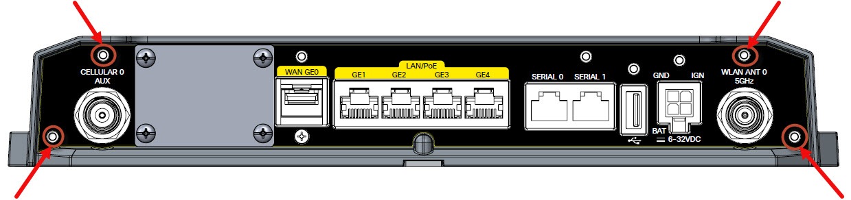
1. Locate the mounting holes on the Cisco IR829. Mounting Holes shows the available mounting holes noted in red.
2. Refer to Bottom Cover Assembly and Top Cover Assembly as a reference to the assembly instructions.
|
1 |
Bottom Cover |
5 |
Top Cover |
|
2 |
Short Screws |
6 |
Long Screws |
|
3 |
Cable Guide Holes |
7 |
Short Screws |
|
4 |
Foam Plugs |
8 |
Guide Holes |
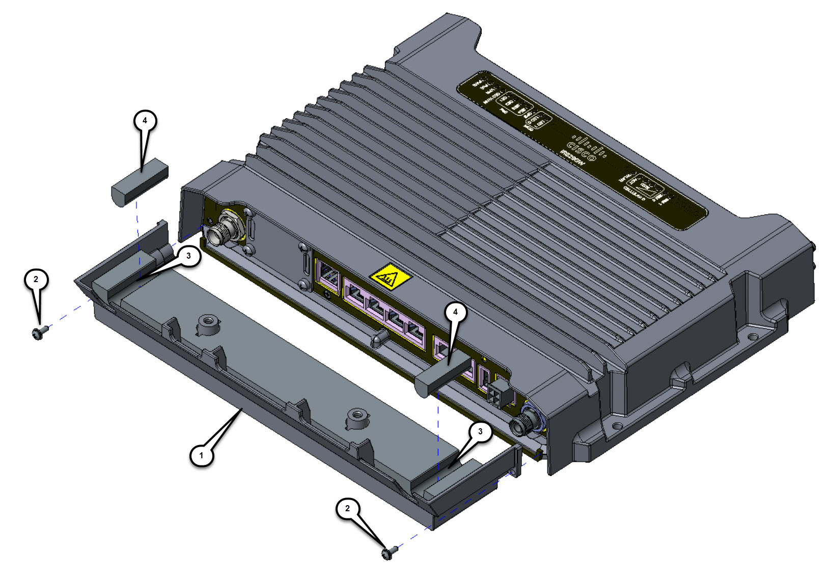
3.. If you have not already done so, attach all cables to their proper connection points on the Cisco IR829 and route them away from the device. Antenna connections are routed through the guide holes (3 ).
Note : All cables should be properly routed and lying flat across the entire width of the bottom cover. Avoid grouping cables together in bundles.
4. Attach the bottom cover (1 ) to the Cisco IR829 using two short screws (2 ). Tighten screws until snug.
5. If your device does not have antennas attached, insert the foam plugs into the cable guide holes.
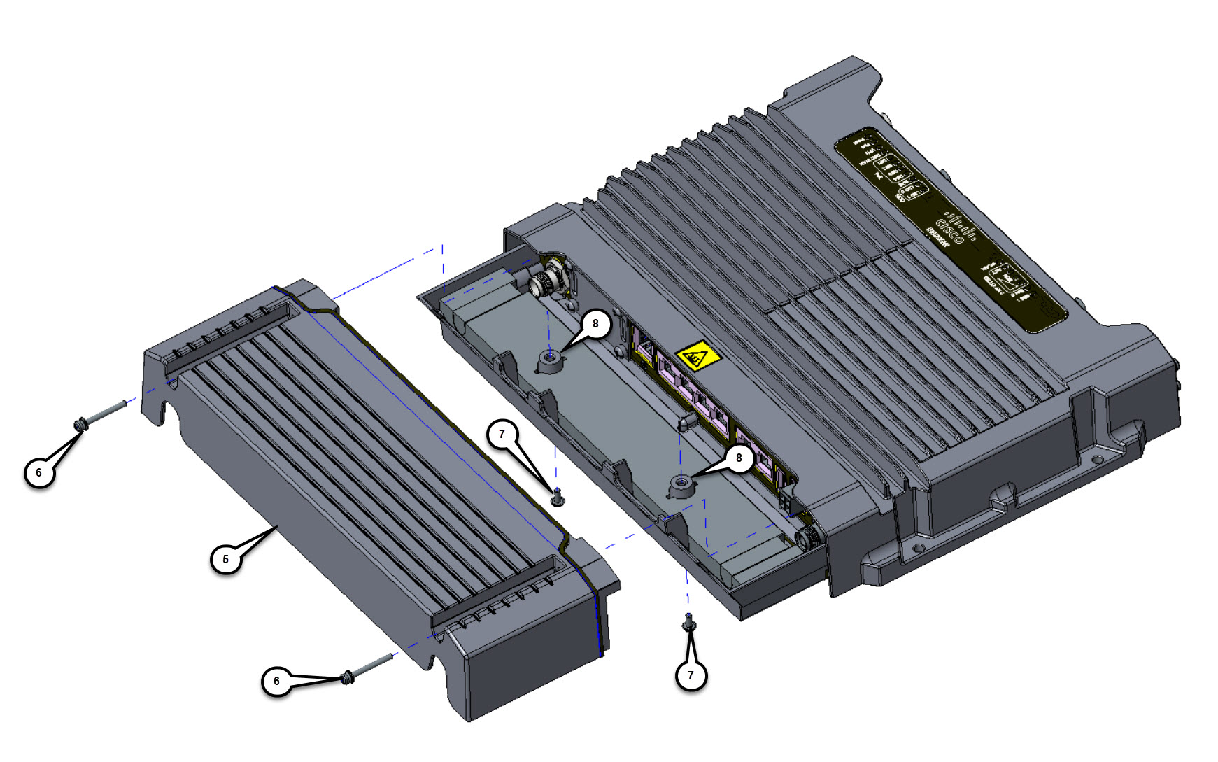
6. Attach the top cover (5 ) to the Cisco IR829 using two long screws (6 ). Tighten screws until snug.
7. Connect the top cover and bottom cover to each other using 2 short screws (7 ). The screws are routed up through the guide holes (8 ) in the lower cover (1 ) and screwed into the top cover (6 ). Tighten screws until snug.
8. Ensure that all of the screws are tightened properly and that the top and bottom covers are properly joined.
 Feedback