Installing the Router

This chapter describes the equipment and the procedures for successfully installing the Cisco IR829 and contains the following sections:

Installing the Router

This chapter describes the equipment and the procedures for successfully installing the Cisco IR829 and contains the following sections:

CAUTION : Do not place anything on top of the router that weighs more than 10 pounds (4.5 kilograms), and do not stack routers on a desktop. Excessive weight on top of the router could damage the chassis.

CAUTION : Do not install the router or power supplies next to a heat source of any kind, including heating vents.

WARNING: Read the installation instructions before connecting the system to the power source. Statement 1004

WARNING: Only trained and qualified personnel should be allowed to install, replace, or service this equipment. Statement 1030

WARNING: No user-serviceable parts inside. Do not open. Statement 1073

WARNING: Ultimate disposal of this product should be handled according to all national laws and regulations. Statement 1040

WARNING: Do not locate the antenna near overhead power lines or other electric light or power circuits, or where it can come into contact with such circuits. When installing the antenna, take extreme care not to come into contact with such circuits, because they may cause serious injury or death. For proper installation and grounding of the antenna, please refer to national and local codes (for example, U.S.:NFPA 70, National Electrical Code, Article 810, Canada: Canadian Electrical Code, Section 54). Statement 1052

WARNING: This product is not intended to be directly connected to the Cable Distribution System. Additional regulatory compliance and legal requirements may apply for direct connection to the Cable Distribution System. This product may connect to the Cable Distribution System ONLY through a device that is approved for direct connection. Statement 1078

Equipment, Tools, and Connections

This section describes the equipment, tools, and connections necessary for installing your Cisco IR829. It contains the following topics:

Items Shipped with your Router

Unpack the box and verify that all items listed on the invoice were shipped with the Cisco IR829.

The following items are shipped with your router:

  • Getting Started Guide Part Number 78-100611
  • Power Cable components
  • Grounding Lug
  • Ethernet Cable Part Number 75-1501-01

Additional Items

The following items are not shipped with the router but are required for installation:

  • ESD-preventive cord and wrist strap.
  • Screws for mounting the router on a wall.
  • Two number-8 wood screws (round- or pan-head) with number-8 washers or two number-8 washer-head screws, for mounting on a wall stud. The screws must be long enough to penetrate at least 3/4 inch (20 mm) into the supporting wood or metal wall stud.
  • Two number-8 wall anchors with washers, for mounting the router on a hollow wall.
  • Wire crimper for chassis grounding.
  • Wire for connecting the chassis to an earth ground.
  • Ethernet cables for connecting to the Fast Ethernet (FE) WAN and LAN ports.
  • Ratcheting torque flathead screwdriver that exerts up to 15 in-lb (1.69 N-m) of pressure.
  • A number-2 Phillips screwdriver.

Ethernet Devices

Identify the Ethernet devices that you will connect to the router: hub, servers, and workstations or PCs. Ensure that each device has a network interface card (NIC) for connecting to Ethernet ports.

If you plan to configure the software using Cisco IOS commands through the console port, provide an ASCII terminal or a PC that is running terminal emulation software to connect to the console port.

Installing the Router

This section describes how to install the Cisco IR829. This router can be installed on a table top or other flat horizontal surface mounted on a wall or DIN rail.

The recommended clearance when horizontally mounted is 1.5 inches on both sides for floor mount bracket clearance and 2 inches on top. Top clearance is not required but stacking heat-dissipating objects on top of the router is not allowed. I/O side clearance is needed as it is required to access the cable connections. Clearance is not required on the backside (opposite side from I/O face) unless DIN rail mounting is required. Clearance is required to attach and mount the DIN rail bracket. The same clearances apply when mounted vertically.

This section also describes how to attach external antennas to the routers and contains the following topics:

Warnings

WARNING: This equipment needs to be grounded. Use a green and yellow 6 AWG ground wire to connect the host to earth ground during normal use. Statement 242

Accessing the SIM Cards

The SIM cards are high reliability, and cellular multihoming support for dual SIM card socket.

The IR800 series of routers use the Mini-SIM (2FF). Specifications are:

  • ISO/IEC 7810:2003, ID-000

  • Length - 25mm, Width - 15mm, Thickness - 0.76mm

  • To ensure a reliable contact to the SIM socket, gold plated SIM cards must be used

This section describes how to install and/or replace a SIM card. Ensure that the router is not mounted to a wall, floor, or DIN rail.

Caution

Do not touch any part of the exposed PCB circuit area when the SIM cover is removed.

Warning

The covers are an integral part of the safety design of the product. Do not operate the unit without the covers installed. Statement 1077

Warning

Hot surface. Statement 1079

Note

High Temperature SIMs are required for 4G operations if the Ambient temperature is above 95F (35C)

To access the SIM card in the Cisco IR829, follow these steps:

  1. Place the router on its bottom and ensure that any installed antennas are carefully oriented.
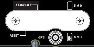
  2. Remove the SIM access panel using two Phillips head screws. (See Accessing the SIM Cards.)
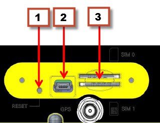
  3. Locate the SIM card you wish to install/replace. Details are shown in Sim Card Detail.
  4. Remove the SIM card (if present) and install the new card(s).
    • To install a card, slide it into the slot, and press it in until it clicks in place. The card is keyed so that you cannot insert it the wrong way.
    • To remove the card, push it in until it releases for it to pop out. Place it in an antistatic bag to protect it from static discharge.
Figure 1. Accessing the SIM Cards
Figure 2. Sim Card Detail

1

Reset Button

2

Mini USB Port

3

Dual Sim Slots

Replace the panel and the screws.

Installing Antennas

NOTE : Before you install the Cisco IR829 Integrated Services Router on a table, wall, or DIN rail, install the antennas on the front panel. It is difficult to install the antennas after the router is installed.

There are two TNC connectors on the front side of the chassis. There are four TNC and one SMA connectors on the back side of the chassis. Two TNC connectors are used to connect to the 4G modem. The four TNC connectors at the back will be connected to the two 4G modems. The front two TNC connectors will be used for WiFi.

Orient the antennas. For optimum wireless performance, the antennas should be perpendicular with respect to the floor.

If the router is being mounted on a desk, orient the antennas straight up.

To attach the radio antennas to your wireless router, follow these steps:

  1. Manually screw the antenna tight to the TNC connectors on the back of the router.
  2. Orient the antennas. For optimum wireless performance, antennas should be generally perpendicular to each other.

Mounting on a Wall, Table, or Other Flat Surface

The Cisco IR829 has mounting holes on the bottom of the chassis for mounting the unit on a wall or other vertical surface. The attachment hardware is provided.


Note

When choosing a location for wall-mounting the router, consider cable limitations and wall structure.

Warning

Read the wall-mounting instructions carefully before beginning installation. Failure to use the correct hardware or to follow the correct procedures could result in a hazardous situation to people and damage to the system. Statement 378

To mount the router on a wall, follow these steps:

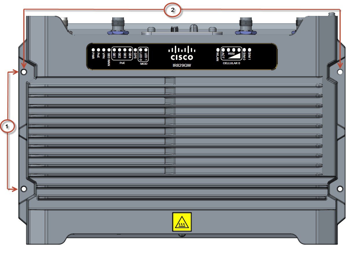
1. Locate the mounting holes on the router. There are 4 holes are shown in Cisco IR829 Mounting Holes. The mounting distance between the holes shown as #1 is 3.94 inches (10.0 cm), and the mounting distance between the holes shown as #2 is 10.64 inches (27.0 cm).

Figure 3. Cisco IR829 Mounting Holes

2. Install the router to a wall stud using two number-8 wood screws, round- or pan-head, with number-8 washers or two number-8 washer-head screws. The screws must be long enough to penetrate at least 1.0 inch (25.4 mm) into the supporting wood or metal wall stud. (See Mounted to wall.)

Figure 4. Mounted to wall

NOTE : For hollow-wall mounting, each bracket requires two wall anchors with washers. Wall anchors and washers must be size number 8.

3. Route the cables so that they do not put a strain on the connectors or mounting hardware. Cables should be routed down relative to the router to prevent water from traveling on the cables.

Installing a DIN Rail

The DIN Rail can be installed in four different orientations. Connectors facing UP is not recommended because of water and dust ingress.

To attach the Cisco IR829 to a DIN rail, follow these steps:

Before you begin

The DIN Rail kit is ordered separately. The PID is IR829-DINRAIL.

Procedure


Step 1

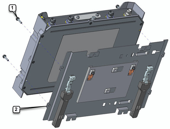
Attach the DIN rail bracket to the back of the router. Align the DIN rail bracket on the back of the router and secure it to the 4 mounting points using the 4 screws provided. See the following figure.

Figure 5. Mounting the DIN Rail Bracket on the Router

Item

Description

1

Mounting screws

2

Mounting holes in DIN bracket

Step 2

Torque the 4 screws to 22-30 in-lbs.

Step 3

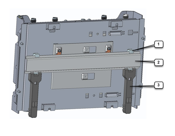
Once the bracket is attached to the router, it can be mounted onto the DIN Rail. See the following figure.

Figure 6. Attaching the Device to the DIN Rail

Item

Description

1

DIN Rail Clips

2

DIN Rail

3

Spring-Loaded Handles

Step 4

Position the router so that the hook on the DIN rail bracket hooks onto the top edge of the DIN rail. The weight of the product can rest on the hook temporarily while the DIN rail bracket latches are secured.

Step 5

Pull down the spring loaded handles at the same time and slide the DIN Rail bracket up and over the latches.

Step 6

Push the DIN rail bracket latch up after the router is over the DIN rail to secure it. The router is now installed in the DIN rail.

Step 7

To remove the router from the DIN Rail, simply reverse the procedure.


Installing the Router Ground Connection

The router must be connected to a reliable earth ground. Install the ground wire in accordance with local electrical safety standards.

WARNING: This equipment must be grounded. Never defeat the ground conductor or operate the equipment in the absence of a suitably installed ground conductor. Contact the appropriate electrical inspection authority or an electrician if you are uncertain that suitable grounding is available. Statement 1024

WARNING: This equipment needs to be grounded. Use a green and yellow 6 AWG ground wire to connect the host to earth ground during normal use. Statement 242

To install the ground connection, follow these steps:

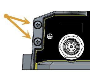
1. Locate the grounding lug attached to the back of the Cisco IR829. It will be attached underneath two screws. Remove the screws holding it to the router and set it aside for reuse.

2. Strip one end of the ground wire to the length required for the terminal.

3. Crimp the ground wire to the grounding lug using the wire crimper.

4. Attach the grounding lug to the chassis using the screws set aside in step 1. Tighten the screw to a torque of 8 to 10 inch-pound (0.9 to 1.1 newton meter). (See Chassis Ground Connection Points .)

Figure 7. Chassis Ground Connection Points

5. Connect the other end of the ground wire to a known reliable earth ground point at your site.

6. If you are using this router in a vehicle, attach the ring terminal to the chassis using one of the screws provided and the green or green and yellow striped wire. Connect the other end of the wire to the vehicle ground.

After you install and properly ground the router, you can connect the power wiring, the LAN cables, and the cables for administrative access as required for your installation.