Install and Upgrade Internal Modules and FRUs

This chapter describes how to install and upgrade internal modules and field replaceable units (FRUs) in the Cisco 1100 Series Integrated Services Routers (ISRs). The install and upgrade information is contained in the following sections:

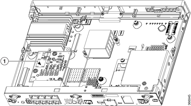
Access the Internal Modules

To access the internal modules on the router, you must first disconnect from the power source and then remove the chassis cover. On how to remove and later replace the chassis cover on the routers, see the Replacing the Cover section for instructions.


Warning

Only trained and qualified personnel should be allowed to install, replace, or service this equipment. Statement 1030


Replace the Chassis Cover

The Cisco 1100 Series ISRs have a removable cover. Do not run the router without the cover. This can cause the router to overheat very quickly. To remove the chassis cover, use a number-2 Phillips screwdriver and perform the following tasks:

Remove the Cover

To remove the cover, perform the following steps:

Procedure

Step 1

Read the Safety Warnings and disconnect the power supply before you perform any module replacement.

Step 2

Confirm the router is turned off and disconnected from the power supply or power supplies. If a redundant power is used, disconnect from the redundant power supply.

Step 3

Place the chassis on a flat surface.

Step 4

Remove all the screws on the both sides of the router; seven on each side.

Step 5

Pull the cover to disengage the slots along the front (bezel) edge of the chassis, as shown in the figure below.
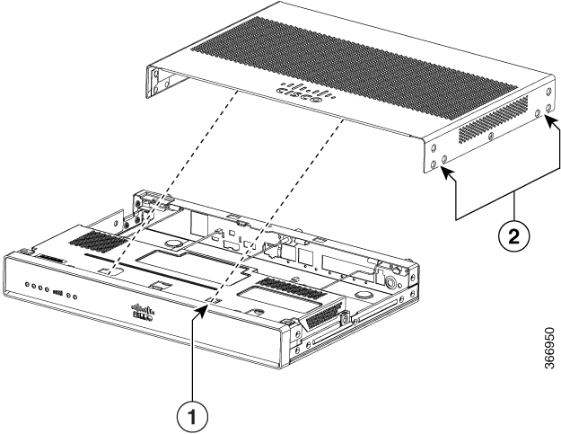
Figure 1. Remove the Cover

1

Slots

2

Screw holes (7 numbers on each side)


Replace the Cover

To replace the cover, perform the following steps.

Procedure

Step 1

Before you begin, read the General Safety Warnings section and then disconnect the power supply.

Step 2

Confirm the router is turned off and disconnected from the power supply (or power supplies) if there is redundant power supply.

Step 3

Place the chassis on a flat surface.

Step 4

Locate the cover hooks on the mating slots and slide the cover towards the bezel side.

Step 5

Install seven screws on each side.


Locate Internal and External Slots for Modules

This section describes the location of internal modules on the router motherboard. Internal modules on the Cisco1100 Series ISRs include- A PoE module and an LTE pluggable module.

Figure 2. Module Location in the Cisco 1100 Series ISR

1

PoE Module

Insert a Micro-SIM Card

This section describes how to insert a Micro-SIM card into a pluggable module.


Caution

Do not touch any part of the exposed PCB circuit area when the Micro-SIM cover is removed.


Figure 3. Insert the Micro-SIM cards
Table 1. Access the Micro-SIM cards

Item

Description

1

Micro-SIM 1 (Towards the device)

2

Micro-SIM 0 (Away from the device)

To insert the Micro-SIM cards into the LTE Pluggable module:

  1. Place the router on its bottom side, remove the screws and then the Micro-SIM cover from the pluggable module.

  2. Push in each Micro-SIM card based on the orientation until it clicks into the slots.

  3. Secure the Micro-SIM cover with a screw. The recommended torque is 2.8 - 3.8 inch LBF.

You have now successfully inserted the Micro-SIM cards into the pluggable module.

Remove and Replace the 1GB Flash Token Memory Stick

The Cisco 1100 Series ISR has a port of 1 GB flash token memory stick to store configurations or Cisco IOS XE consolidated packages.


Note

Only Cisco 1GB Flash memory modules are supported on Cisco routers.

Caution

Do not remove a USB Flash memory module when issuing some file access command or a read/write operation to the Flash memory module when it is processing. The router might reload or the USB Flash memory module can be damaged. You can check to see if the USB activity LED on the router front panel is flashing, prior to the removal of the USB device


Procedure


Step 1

To remove, pull the 1GB flash token memory stick from the USB port.

Step 2

To insert, push the 1GB flash token memory stick into the USB port.

The flash memory module can be inserted or removed regardless of whether the router is powered up or not.


Remove and Replace the Cisco 1100 Series ISRs Power Supplies

A single 4-pin power connector type shared with 12V main power and -54V PoE supply is used for C111x Series.

  • Single output - 66W +12V power supply for Non-PoE capable units.

    Dual output - 66W + 12V, 83W -53.5V power supply. 150W power supply for PoE capable units.

    For all supplies (C1100 Series):

    • Input - Voltage range is 100 – 240V AC. Frequency range is 50 – 60Hz.

    • Output - 12V DC / -54V DC.

  • 30W AC power supply (C1101-4P/C1101-4PLTEPWx Series)

  • A single power connector type is used for Cisco 1100 Series ISR. Connector is capable of conducting 5A.

  • The power connector has a locking mechanism to prevent the connector from being disengaged inadvertently.


Warning

Blank faceplates and cover panels serve three important functions: they prevent exposure to hazardous voltages and currents inside the chassis; they contain electromagnetic interference (EMI) that might disrupt other equipment; and they direct the flow of cooling air through the chassis. Do not operate the system unless all cards, faceplates, front covers, and rear covers are in place. Statement 1029

Warning

This unit might have more than one power supply connection. All connections must be removed to de-energize the unit. Statement 1028

Warning

Care should be taken while removing the power supplies and power inverters (especially in boost mode of operation). If the total power consumption is higher than can be supported by one power supply alone and in this condition a power supply is removed, the hardware can be damaged. This may then result in the system being unstable or unusable.

Install and Remove SFP Modules

This section describes how to install optional small-form-factor pluggable (SFP) modules in the router to provide optical Gigabit Ethernet connectivity.

The SFP module installs into a slot on the rear panel of C111x series.

Only SFP modules certified by Cisco are supported on the routers. For more information, refer to SFPs Supported on Cisco 1100 ISRs


Note

Currently, GLC-GE-100FX V01 is not supported.


Remove the SFP Modules

To remove an SFP module from the router:


Warning

Invisible laser radiation may be emitted from disconnected fibers or connectors. Do not stare into beams or view directly with optical instruments. Statement 1051

Procedure


Step 1

Disconnect the power supply before you remove any module.

Step 2

Disconnect all cables from the SFP.

Step 3

Disconnect the SFP latch.

Note 
SFP modules use various latch designs to secure the module in the SFP port. For information on the SFP technology type and model, see the label on the side of the SFP module.
Tip 
Use a pen, screwdriver, or other small straight tool to gently release a bale-clasp handle if you cannot reach it with your fingers.
Step 4

Grasp the SFP on both sides and remove it from the router.