Introduction to this Document
This Release Notes document provides information about the Cisco Catalyst IR1101 Rugged Series Routers, Cisco Catalyst IR1800 Rugged Series Routers, Cisco Catalyst IR8140 Heavy Duty Series Routers, Cisco Catalyst IR8340 Rugged Series Routers, and Cisco ESR6300 Embedded Series Routers running Cisco IOS XE 17.12.1a.
This document describes the new features, limitations, troubleshooting, besides providing recommended configurations, caveats, and information on how to obtain support and documentation.
 Note |
The documentation set for this product strives to use bias-free language. For purposes of this documentation set, bias-free is defined as language that does not imply discrimination based on age, disability, gender, racial identity, ethnic identity, sexual orientation, socioeconomic status, and intersectionality. Exceptions may be present in the documentation due to language that is hardcoded in the user interfaces of the product software, language used based on RFP documentation, or language that is used by a referenced third-party product. |
Cisco Catalyst IR1101 Rugged Series Router
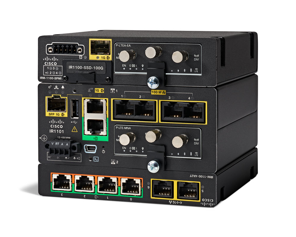
The Cisco Catalyst IR1101 Rugged Series Router is a next-generation modular industrial router, which has a base platform with additional pluggable modules that can be added. The pluggable modules provide the flexibility of adding different interfaces to the IR1101 platform, for example, a cellular module, which provides 5G and Fourth-Generation Long-Term Evolution (4G LTE) cellular networks.
The IR1101 also has expansion modules that adds key capabilities to the IR1101. The expansion modules are:
|
SKU ID |
Description |
|---|---|
|
IRM-1100-SPMI |
Expansion Module with 1 GE SFP, 1 Pluggable Module, 4 GPIO ports on 1 Digital I/O Connector, and 1 mSATA SSD Slot. |
|
IRM-1100-SP |
Expansion Module with 1 GE SFP and1 Pluggable Module. |
|
IRM-1100-4A2T |
Expansion Module with an additional four asynchronous serial ports and two Ethernet RJ45 LAN interfaces. |
|
Cellular pluggable modules |
A number of pluggable modules are available for cellular connectivity. |
|
IRM-SSD-100G |
100 GB pluggable industrial SSD. |
|
P-LPWA-XXX |
|
|
P-LTE-450 |
Cisco 450MHz Category-4 LTE Pluggable Interface Module. |
Cisco Catalyst IR1800 Rugged Series Router
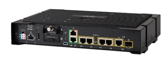
The Cisco Catalyst IR1800 Rugged Series Router is a modular industrial router. The IR1800 series has four base platforms with additional pluggable modules that can be added. The pluggable modules provide the flexibility of adding different interfaces to the base platform.
The IR1800 series consists of four base platforms:
-
IR1821
-
IR1831
-
IR1833
-
IR1835
The IR1800 series features a base platform with modularity, which includes:
|
SKU ID |
Description |
|---|---|
|
IRM-GNSS-ADR |
GPS Module with Automotive Dead Reckoning. |
|
WP-WIFI6-x |
Wi-Fi 6 Network Interface Module (NIM). |
|
Cellular pluggable modules |
A number of pluggable modules are available for cellular connectivity. |
|
IRM-SSD-100G |
100 GB pluggable industrial SSD. |
|
Feature |
IR1821 |
IR1831 |
IR1833 |
IR1835 |
|---|---|---|---|---|
|
Processor Frequency |
600 MHz |
600 MHz |
600 MHz |
1200 MHz |
|
DDR Memory |
4 GB |
4 GB |
4 GB |
8 GB |
|
Flash Storage |
4 GB |
4 GB |
4 GB |
8 GB |
|
PIM Slot |
1 |
2 |
2 |
2 |
|
Wi-Fi-6 NIM Module Slot |
1 |
1 |
1 |
1 |
|
PoE |
No |
No |
Yes |
Yes |
|
SSD Module Slot |
No |
No |
Yes |
Yes |
|
GPS FRU Module Slot |
No |
No |
Yes |
Yes |
|
Digital I/O |
No |
No |
No |
Yes |
|
Asynchronous Serial Interface |
(1) RS232 DTE |
(1) RS232 DTE (1) RS232 DCE |
(1) RS232 DTE (1) RS232 DCE |
(1) RS232 DTE (1) RS232 DCE/RS485 |
Cisco Catalyst IR8140 Heavy Duty Series Router
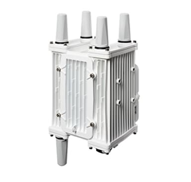
The Cisco Catalyst IR8140 Heavy Duty Series Router (IR8140H), is a next-generation modular IP67 Industrial Router for outdoor use.
These are the two IR8140H models:
-
IR8140H-P-K9 (with PoE PSE)
-
IR8140H-K9 (without PoE PSE)
The IR8140H series features contains four external module slots plus two onboard WAN ports, and supports the following:
-
60-W PSU
-
CPU 1.2 GHz
-
8GB RAM
-
8GB Flash Storage
-
GPS onboard receiver
-
900-MHz WPAN – OFDM/FSK Module
-
mSATA module
-
1x 1-Gigabit Ethernet SFP WAN
-
1x 1-Gigabit Ethernet Cu WAN
-
PoE (15 W) supported only in the IR8140H-P-K9 PID
-
12VDC_OUT port (only available when PoE is not in use)
-
Battery Backup Units (BBUs): Up to three
-
2x Alarm ports (Digital I/O)
-
IRMH modules for CAT 4 LTE, CAT 6 LTE, CAT 18 LTE, and 5G
Cisco Catalyst IR8340 Rugged Series Router
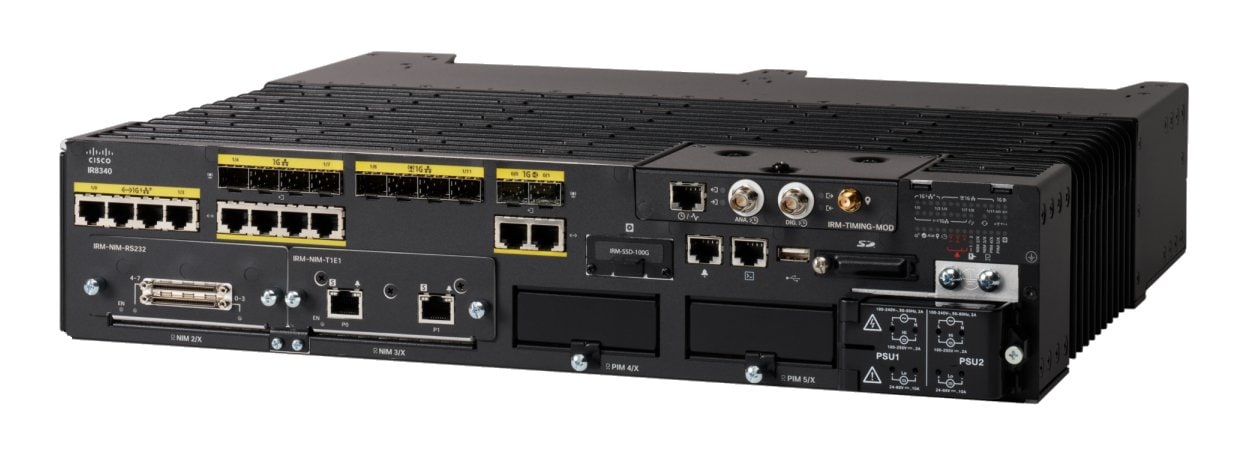
The Cisco Catalyst IR8340 Rugged Series Router, is the first all-in-one industrial-grade, integrated routing, switching, and security platform.
The IR8340 router features two Pluggable Interface Module (PIM) slots, two single-wide IRM-NIM slots, plus 12 onboard LAN ports, and two WAN ports, and supports the following:
-
150W or 250W PSU, low-voltage DC and high-voltage AC/DC options
-
PTP on LAN ports - Default, power and Dot1as profiles
-
Dual slots for 5G and 4G LTE PIM
-
T1/E1 Network Interface Modules (NIM)
-
8-port Asynchronous/Synchronous Network Interface Module (NIM) IRM-NIM-RS232
-
mSATA module
-
2 x 1-G Combo WAN ports
-
4 x 1-G Copper LAN ports
-
4 x 1-G Combo LAN ports
-
4 x 1-G SFP LAN ports
-
PoE PoE+ UPoE (up to 60 W) support on LAN ports 1-4
-
2 x IN and 1 x OUT Alarm ports (RJ45)
Cisco ESR6300 Embedded Series Router
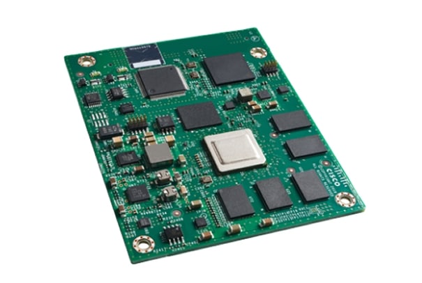
The ESR6300 is a small form factor embedded router module with a board size of 3.0 in. x 3.775 in. (76.2 mm x 95.885 mm).
The more compact design simplifies integration and offers system integrators the ability to use the Cisco ESR6300 in a wide variety of embedded applications. The ESR module is available with a Cisco-designed cooling plate customized to the ESR, as well as without the cooling plate for system integrators who want to design their own custom thermal solution.
There are two ESR6300 SKUs:
-
ESR-6300-NCP-K9: Embedded Router Board without a cooling plate
-
ESR-6300-CON-K9: Embedded Router Board with a cooling plate
Both SKUs offer the following port and module interfaces:
-
Four GE LAN ports
-
Two combo GE WAN ports
-
One USB 3.0 port
-
One mSATA module interface
Interface Naming Conventions
Cisco Catalyst IR1101 Rugged Series Router
The following section shows the names of the interfaces on each of the IoT routers.
| Port |
Naming Convention |
|---|---|
|
Gigabit Ethernet combo port |
GigabitEthernet0/0/0 |
|
Gigabit Ethernet SFP port on IRM-1100 |
GigabitEthernet0/0/5 |
|
Gigabit Ethernet on IRM-1100-4A2T mounted on the Expansion side |
gigabitetherenet 0/0/5 gigabitetherenet 0/0/6 |
|
Fast Ethernet ports |
FastEthernet0/0/1 FastEthernet0/0/2 FastEthernet0/0/3 FastEthernet0/0/4 |
|
Cellular Interface on IR1101 Base |
Cellular 0/1/0 Cellular 0/1/1 |
|
Cellular Interface on IRM-1100 mounted on the top (EM) side |
Cellular 0/3/0 Cellular 0/3/1 |
|
Cellular Interface on IRM-1100 mounted on the bottom (CM) side |
Cellular 0/4/0 Cellular 0/4/1 |
|
Asynchronous Serial Interface Base |
Async0/2/0 |
|
IRM-1100-4A2T is mounted on the top (EM) side |
async 0/3/0 async 0/3/1 async 0/3/2 async 0/3/3 |
|
IRM-1100-4A2T is mounted on the bottom (CM) side |
async 0/4/0 async 0/4/1 async 0/4/2 async 0/4/3 |
|
USB |
usbflash0: |
|
mSATA |
msata |
|
IR1101 Base Unit Alarm input |
alarm contact 0 |
|
GPIO on IRM-1100 |
alarm contact 1-4 |
|
LoRaWAN interface on IR1101 Base |
LORAWAN0/1/0 |
|
LoRaWAN interface on the top (EM) side |
LORAWAN0/3/0 |
|
Gigabit Ethernet interface for LTE 450MHz module on IR1101 Base |
GI0/1/0 GI0/1/0.x for multiPDN operation |
|
Gigabit Ethernet interface for LTE 450MHz module mounted on the bottom (CM) side |
GI0/4/0 |
Cisco Catalyst IR1800 Rugged Series Router
| Port |
Naming Convention |
|---|---|
|
Gigabit Ethernet combo port |
GigabitEthernet0/0/0 |
|
Gigabit Ethernet ports |
GigabitEthernet0/1/0 GigabitEthernet0/1/1 GigabitEthernet0/1/2 GigabitEthernet0/1/3 |
|
Cellular Interface |
Cellular 0/4/0 Cellular 0/4/1 Cellular 0/5/0 Cellular 0/5/1 |
|
Asynchronous Serial Interface |
Async0/2/0 Async0/2/1 (when the base platform supports two asynchronous serial interfaces) |
|
Wi-Fi Interface |
Wl0/1/4 |
|
USB |
usbflash0: |
|
mSATA |
msata |
|
GPIO |
alarm contact 1-4 |
Cisco Catalyst IR8140 Heavy Duty Series Router
| Port |
Naming Convention |
|---|---|
|
Gigabit Ethernet ports |
GigabitEthernet0/0/0 GigabitEthernet0/0/1 |
|
Cellular Interface |
Cellular 0/2/0 OR Cellular 0/3/0 |
|
SSD |
Virtual port Group0 |
|
WPAN |
Wpan 0/1/0 Wpan 0/2/0 Wpan 0/3/0 |
|
Digital IO |
alarm contact 1-2 |
Cisco Catalyst IR8340 Rugged Series Router
| Port |
Naming Convention |
|---|---|
|
Gigabit Ethernet WAN ports |
GigabitEthernet0/0/0 GigabitEthernet0/0/1 |
|
Gigabit Ethernet LAN ports |
GigabitEthernet0/1/0 GigabitEthernet0/1/1 GigabitEthernet0/1/2 GigabitEthernet0/1/3 GigabitEthernet0/1/4 GigabitEthernet0/1/5 GigabitEthernet0/1/6 GigabitEthernet0/1/7 GigabitEthernet0/1/8 GigabitEthernet0/1/9 GigabitEthernet0/1/10 GigabitEthernet0/1/11 |
|
Cellular Interface |
Cellular 0/4/0 Cellular 0/4/1 Cellular 0/5/0 Cellular 0/5/1 |
|
NIM Interface (Asynchronous/Synchronous Serial Ports or E1/T1 ports) |
0/2/0 0/2/1 0/3/0 0/3/1 |
|
mSATA SSD |
msata |
|
GPIO |
alarm contact 1-2 |
|
USB Port |
usb0: |
|
Console Port |
Line console 0 |
Cisco ESR6300 Embedded Series Router
| Port |
Naming Convention |
|---|---|
|
Gigabit Ethernet combo port WAN Layer3 |
GigabitEthernet0/0/0 GigabitEthernet0/0/1 |
|
Gigabit Ethernet LAN Layer 2 ports |
GigabitEthernet0/1/0 GigabitEthernet0/1/1 GigabitEthernet0/1/2 GigabitEthernet0/1/3 |
|
Cellular Interface |
Cellular 0/3/0 |
|
USB Port |
usbflash0: (IOS and rommon) |
|
Console Port |
Line console 0 |
Software Images for Cisco IOS XE Release 17.12.1a
Note |
You must have a Cisco.com account to download the software. |
Cisco IOS XE Release 17.12.1a includes the following Cisco images.
|
Router |
Image Type |
Filename |
|---|---|---|
|
IR1101 |
Universal |
ir1101-universalk9.17.12.1a.SPA.bin ir1101-universal9_npe.17.12.1a.SPA.bin |
|
IR1800 |
Universal |
IR1800-universalk9.17.12.1a.SPA.bin |
|
IR8140 |
Universal |
IR8100-universalk9.17.12.1a.SPA.bin |
|
IR8340 |
Universal UTD Engine for Cisco ISR1100/ISR1100X and IOS XE |
IR8340-universalk9.17.12.1a.SPA.bin utd.17.12.01a.1.0.7_SV3.1.55.0_XE17.12.x86_64.tar |
|
ESR6300 |
Universal |
c6300-universalk9.17.12.1a.SPA.bin |
The latest software downloads for the routers can be found at:
https://software.cisco.com/download/home/286323433
Click the link corresponding to your device to take you to the specific software you are looking for.
Cellular Module Modem Firmware, OEM/PRI for Cisco IoT Polaris Platforms
This section contains the latest modem firmware available for each of the modems used by the Cisco IoT Industrial routers.
Note |
Cisco IOS XE updates do not automatically update the modem firmware. The user should check and update to the latest firmware. See the following table for the latest information: |
See the Cisco Firmware Upgrade Guide for 4G LTE and 5G Cellular Modems for upgrade instructions.
|
Cellular Module |
Modem |
Firmware Version |
Software Download Link |
|---|---|---|---|
|
P-LTEAP18-GL IRMH-LTEAP18-GL |
LM960 |
32.00.1x7 |
|
|
P-5GS6-GL |
FN980 |
— |
|
|
P-LTE-450 |
IPS-701 |
— |
Firmware upgrades are only available through the manufacturer Intelliport. See the 450MHz Category-4 LTE PIM chapter of the Cellular Pluggable Interface Module Configuration Guide. |
|
P-LTEA-EA IRMH-LTEA-EA |
EM7455 |
02.32.11.00 |
|
|
P-LTEA-LA IRMH-LTEA-LA |
EM7430 |
02.33.03.00 |
|
|
P-LTE-VZW |
WP7601 |
02.37.0x.00 |
|
|
P-LTE-US |
WP7603 |
02.37.0x.00 |
|
|
P-LTE-JN |
WP7605 |
02.28.03 |
|
|
P-LTE-GB |
WP7607 |
02.37.03.05 |
|
|
P-LTE-IN |
WP7608 |
02.28.03 |
|
|
P-LTE-AU |
WP7609 |
02.28.03 |
|
|
P-LTE-MNA |
WP7610 |
02.37.0x.00 |
New Features in Cisco IOS XE 17.12.1a
The following sections describe the major enhancements available in Cisco IOS XE 17.12.1a on each of the routers.
Major Enhancements in IR1101
This section describes the new features for the IR1101.
Also see the Major Enhancements Common to all IoT Routers.
Support for P-LTE-450
The P-LTE-450 is a 450MHz Category-4 LTE PIM, which addresses LTE use cases primarily targeting utility, public safety, and critical infrastructure maintained by public organizations in Europe and other world regions. The module supports only Band 31 and 72 for LTE 450MHz networks.
Note |
Throughout the user documentation, you will see the module referred to as P-LTE-450, which is the Cisco product name. The module is designed and manufactured by Intelliport, which refers to it as the IPS-701. Both names will be present in documentation. |
Unlike regular LTE modules, there are some differences with regards to the P-LTE-450MHz on IOS-XE platform. Some of the key differences are:
-
IP pass through will be on Gigabit Ethernet interfaces rather than cellular interface
-
Troubleshooting commands are from web interface of third-party hardware
See the Cellular Pluggable Interface Module Configuration Guide for complete details.
For additional information, see the LTE 450MHz Alliance.
HDLC Support for SCATS
The Sydney Coordinated Adaptive Traffic System (SCATS), is an intelligent transportation system that manages the dynamic (on-line, real-time) timing of signal phases at traffic signals, meaning that it tries to find the best phasing (i.e. cycle times, phase splits and offsets) for a traffic situation (for individual intersections as well as for the whole network).
High-Level Data Link Control (HDLC) is a group of data link (Layer 2) protocols used to transmit synchronous data packets between point-to-point nodes. Data is organized into addressable frames.
This feature is being developed as an IOx app which integrates with the existing virtualization layers available in IOS XE based IoT routers. The intended application is to have a SCATS controller connected to the router via serial cable.
The following figure is an example of a typical SCATS traffic control network application:
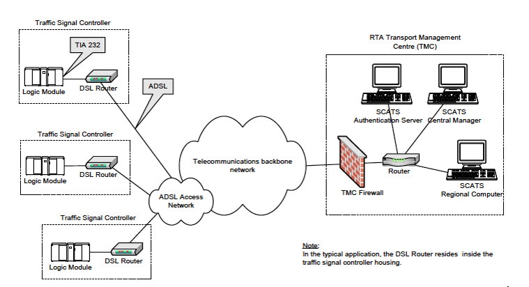
In the above figure, an IR1101 plays the role of the DSL Router to which the Traffic Signal Controller (TSC) is connected via a serial interface. Upon connection to the TSC, the router obtains a Site ID from the controller, which it will then forward to the SCATs Authentication Server. The authentication servers will be provided to the IOx app through a JSON file including IP and port and there can be up to three authentication servers that the IOx app can cycle through.
Once the Authentication Server has received the Site ID, it will reply to the router with the corresponding SCATs regional computer IP and port that matches that Site ID. All further communication is then done transparently from TSC to Regional Computer.
The router will use two modes to communicate with the TSC (HDLC and non-HDLC). There are four available serial configurations, and the user can select which configurations will be used by enabling or disabling them through a second JSON file provided to the app.
Since this is an IOx app, the feature can be disabled by stopping, deactivating, or uninstalling the app. The application will mainly be deployed using Local Manager. App size is about 50 MB, CPU is 400 units and memory is 128 MB.
Major Enhancements in IR1800
This section describes the new features for the IR1800.
Also see the Major Enhancements Common to all IoT Routers.
Access Accelerometer and Gyro Sensor Data from IRM-GNSS
This feature allows accelerometer and gyro sensor data from IRM-GNSS (GPS DR) module to be streamed to the IOX via a TTY in IR1800. Prior to this release, the IRM-GNSS module pushed the sensor data to the host in NMEA via port /dev/ttyS2. Previous IOS XE releases already parsed and cached the data.
The feature will forward the sensor data to IOX via the TTY whenever the data is received from the NMEA. Currently, there is no control on the frequency the data is sent from the module, which totally relies on the module itself.
There are no new commands for this feature. It is enabled by default once dead reckoning is enabled. Existing CLIs can be used to view the sensor data, for example:
Router# show platform hardware gps dead-reckoning

DR Vehicle interface mode: OBDDII
GPS/DR Vendor Info: TELIT
GPS/DR module FW Version: V33-1.0.5-CLDR-4.7.10-N115R115-003291-3
…
Raw Accel Data in X:  -542
Raw Accel Data in Y:  538
Raw Accel Data in Z:  16964
Raw Gyro Data in X:  153
Raw Gyro Data in Y:  -80
Raw Gyro Data in Z:  99
The existing debug platform hardware gps dead-reckoning command has been enhanced to provide additional debug messages for better serviceability. The debug messages will cover the following:
-
How frequent the sensor data are pushed from the module to IOS, it must at least once per second.
-
The latest sensor data received from the module.
5G Standalone Mode (SA) Support
This feature provides 5G Standalone mode (SA) support on the P-5GS6-GL pluggable module. The 5G SA mode support will enable 5G cellular configuration display using Cisco IOS-XE CLI commands.
This feature provides a mechanism in the CLI to select a set of bands for SA mode, as opposed to a single band in previous software releases. The following IOS-XE CLIs have been modified for 5G SA mode support:
-
show cellular radio
-
show cellular radio details (without carrier aggregation)
-
show cellular network
There is also a band selection CLI to select cellular bands.
Show Command Examples
Router#show cellular 0/2/0 radio
Radio power mode = Online
5G Rx Channel Number = 632544
5G Tx Channel Number = 632544
5G-SA Band = 78
Bandwidth = 20 MHz
Current 5G RSSI = -60 dBm
Current 5G RSRP = -71 dBm
Current 5G RSRQ = -11 dB
Current 5G SNR = 34.5 dB
Physical Cell Id = 500
Radio Access Technology(RAT) Preference = AUTO
Radio Access Technology(RAT) Selected = 5GNR-SA
Router#show cellular 0/4/0 radio detail
 Modem Radio is Online
 Main 0 Antenna details:
 RSSI = -38 dBm
 RSRP = -48 dBm
 Diversity 0 Antenna details:
 RSSI = -47 dBm
 RSRP = -58 dBm
Router#show cellular 0/4/0 network
Current System Time = Sun Jan 6 0:4:36 1980
Current Service Status = Normal
Current Service = Packet switched
Current Roaming Status = Home
Network Selection Mode = Automatic
Network = Test PLMN 1-1
Mobile Country Code (MCC) = 1
Mobile Network Code (MNC) = 1
Packet switch domain(PS) state = Attached
Tracking Area Code (TAC) = 1
Cell ID = 1024
Negotiated network MTU = 1500
Band Selection Command Example
The lte modem band-select CLI can be used to enable bands that the user wishes to use and subscribe to. By default SA bands are not available.
Important |
If you wish to use SA bands, the lte modem band-select command MUST be used as part of the configuration. |
The following is an example of the command:
conf t
controller cellular 0/2/0
lte modem band-select indices umts3g all lte4g all nr5g-NSA all nr5g-SA 78 slot 0
exit
The following shows an example of using nr5g-sa band 48:
lte modem band-select indices umts3g "23" lte4g "7" nr5g-nsa "12" nr5g-sa "48" slot 0Note |
In the above example, umts3g band 23, lte4g band 7, and nr5g-nsa band 12 are not available in the area, which means the modem will only attach to nr5g-nsa band 48. |
The following shows an example of using nr5g-sa band 78:
lte modem band-select indices umts3g "23" lte4g "7" nr5g-nsa "78" nr5g-sa "none" slot 0Note |
In the above example, umts3g band 23 and lte4g band 7 are not available in the area, and nr5g-sa bands are turned off which means the modem will only attach to nr5g-nsa band 78. |
Limitations
none is an invalid option for umts3g, lte4g, and nr5g-nsa.
Major Enhancements in IR8140
There are no new features specifically for the IR8140.
Also see the Major Enhancements Common to all IoT Routers.
Major Enhancements in IR8340
This section describes the new features for the IR8340.
Also see the Major Enhancements Common to all IoT Routers.
Unified Thread Defense (UTD)
Unified Thread Defense (UTD) is Cisco's premier network security solution which provides a comprehensive suite of security features, such as firewall capabilities, monitoring, alerts, and IDS/IPS, Web-Filtering, Multi-tenancy and Anti-Malware Protection.
IR8340 Limitations
The following are product specific limitations:
-
A minimum of 1.8 GB must be available to being up UTD Container.
-
UTD is supported in both Autonomous mode and Controller Mode, but in Autonomous mode, only IPS/IDS features are supported.
-
The UDT configuration supports the Cloud-Low profile only.
-
On-Box Web-Filtering Database is not supported.
License and Supported Features in Autonomous and Controller Mode
Controller Mode:
-
License is not required in controller mode. We do not have a concept of licenses in controller mode.
-
Supports multi-tenancy, URLF, and SSLProxy.
-
AMP and DNS security has not been validated for this release.
Autonomous Mode:
-
UTD is supported in both Network Essentials and Network Advantage licenses.
-
URLF, SSLProxy, and multi tenancy are not supported.
Feature Configuration
Configuration on the IR8340 is the same as on other products. For information please refer to:
PTP Over PRP
Beginning with the Cisco IOS XE 17.12.1a release, Precision Time Protocol (PTP) can operate over Parallel Redundancy Protocol (PRP) on the Cisco Catalyst IR8340 Rugged Series Router. The support for PTP over PRP is the same as that on the Cisco Catalyst IE9300 Rugged Series Switches. Full documentation is available in the Redundancy Protocol Configuration Guide, Cisco Catalyst IE9300 Rugged Series Switches.
The following details pertain to the IR8340:
-
Supported PTP clock and profiles:
-
Boundary Clock (BC) – Default Profile, Power profile
-
Transparent Clock (TC) – Peer-to-peer transparent (P2P)
-
-
The PTP over PRP will be supported for only one PTP clock domain at any given time
-
There are 2 PRP channels:
-
Channel 1: Ports Gig0/1/4 and Gig0/1/5
-
Channel 2: Ports Gig0/1/6 and Gig0/1/7
-
-
PTP over PRP is supported with GNSS/Telecom enabled on the system. The Redbox shall be in PRTC/Wan to LAN conversion mode, with ports being in Master state only.
-
The other clock domains can have non PRP interfaces configured with PTP over PRP enabled on one domain.
WAN MACsec and MKA Support
MACsec is an IEEE 802.1AE standards based Layer 2 hop-by-hop encryption that provides data confidentiality and integrity for media access independent protocols.
MACsec, provides MAC-layer encryption over wired networks by using out-of-band methods for encryption keying. The MACsec Key Agreement (MKA) Protocol provides the required session keys and manages the required encryption keys.
The 802.1AE encryption with MACsec Key Agreement (MKA) is supported on downlink ports for encryption between the routers or switches and host devices.
MACsec encrypts the entire data except for the Source and Destination MAC addresses of an Ethernet packet. To provide MACsec services over the WAN, service providers offer Layer 2 transparent services such as E-Line or E-LAN using various transport layer protocols such as Ethernet over Multiprotocol Label Switching (EoMPLS) and L2TPv3.
The packet body in an EAP-over-LAN (EAPOL) Protocol Data Unit (PDU) is referred to as a MACsec Key Agreement PDU (MKPDU). When no MKPDU is received from a participants after 3 hearbeats (each hearbeat is of 2 seconds), peers are deleted from the live peer list For example, if a client disconnects, the participant on the switch continues to operate MKA until 3 heartbeats have elapsed after the last MKPDU is received from the client.
The MKA feature support provides tunneling information such as VLAN tag (802.1Q tag) in the clear so that the service provider can provide service multiplexing such that multiple point to point or multipoint services can co-exist on a single physical interface and differentiated based on the now visible VLAN ID.
In addition to service multiplexing, VLAN tag in the clear also enables service providers to provide quality of service (QoS) to the encrypted Ethernet packet across the SP network based on the 802.1P (CoS) field that is now visible as part of the 802.1Q tag.
Major Enhancements in ESR6300
This section describes the new features for the ESR6300.
Also see the Major Enhancements Common to all IoT Routers.
DLEP IPv6 Unicast
Previous releases of IOS XE offered support for IPv4 unicast traffic over an IPv4 DLEP session. IOS XE 17.12.1a provides support for IPv6 unicast over an IPv4 DLEP session.
This section provides a subset of the overall DLEP information that is found in the IP Routing Configuration Guide, Cisco IOS XE 17.x.
Feature Limitations
DLEP has the following restrictions and limitations:
-
Multicast traffic is not supported with DLEP, but is supported with PPPOE.
-
DLEP cannot be deployed with High Availability (HA) configuration.
-
You must configure the VMI and Virtual-Template before attaching the Virtual-Template to a physical interface.
-
The ESR6300 is connected over DLEP radio links and only 1 radio per interface (WAN port only) is supported.
-
All configurations for the virtual-template need to be removed individually using the no form of the respective configuration commands, before removing the virtual-template using the no interface virtual-template command.
-
Changing of configurations on the virtual-template and VMI interfaces is not supported while DLEP is enabled on the physical interface. In order to make such changes, disable DLEP by removing the DLEP configuration from the physical interface, make the changes, and re-configure DLEP on the physical interface.
-
DLEP interface does not support Jumbo frames (frames > 1500 bytes in size).
-
Routing of internally generated application traffic (e.g. pingv6) with source as DLEP VMI / physical interface is not supported.
-
Viewing information about DLEP neighbors using the show ipv6 neighbor command is not supported.
Configuring DLEP with IPv6 Unicast
Use the following steps to configure DLEP with IPv6 Unicast.
Enable IPv6 unicast routing:
Router#configure terminal
Router(config)#ipv6 unicast-routing
Router(config)#end
Router#
Enable IPv6 on the physical interface:
Router#configure terminal
Router(config)#interface GigabitEthernet0/0/0
Router(config-if)#ipv6 enable
Router(config-if)#end
Router#
Configure the virtual template interface:
Router#configure terminal
Router(config)#interface virtual-template1
Router(config-if)#ip unnumbered GigabitEthernet0/0/0
Router(config-if)#ipv6 enable
Router(config-if)#ipv6 nd dad attempts 0
Router(config-if)#end
Router#
Configure the vmi interface:
Router#configure terminal
Router(config)#interface vmi1
Router(config-if)#ip unnumbered GigabitEthernet0/0/0
Router(config-if)#physical-interface GigabitEthernet0/0/0
Router(config-if)#ipv6 enable
Router(config-if)#end
Router#
Configure the physical interface:
Router#configure terminal
Router(config)#interface GigabitEthernet0/0/0
Router(config-if)#ip address 10.1.1.1 255.255.255.0
Router(config-if)#ipv6 address 1000::1/64
Router(config-if)#ip dlep vtemplate 1
Router(config-if)#end
Router#
Configuring EIGRP for DLEP IPv6 Unicast
Use the following steps to configure EIGRP for DLEP IPv6 Unicast:
Create the EIGRP router:
Router#configure terminal
Router(config)#ipv6 router eigrp 2
Router(config-rtr)#eigrp router-id 2.2.2.2
Router(config-rtr)#end
Router#
Configure EIGRPv6 on VMI:
Router#configure terminal
Router(config)#interface vmi1
Router(config-if)#ipv6 eigrp 2
Router(config-if)#no ipv6 split-horizon eigrp 2
Router(config-if)#end
Router#
Configuring OSPF for DLEP IPv6 Unicast
Use the following steps to configure OSPF for DLEP IPv6 Unicast.
Configure OSPF router:
Router#configure terminal
Router(config)#router ospfv3 1
Router(config-router)#router-id 200.200.200.200
Router(config-router)#address-family ipv6 unicast
Router(config-router-af)#end
Router#
Configure OSPF on the VMI interface:
Router#configure terminal
Router(config)#interface vmi1
Router(config-if)#ospfv3 1 ipv6 area 0
Router(config-if)#ospfv3 1 ipv6 cost dynamic
Router(config-if)#ospfv3 1 ipv6 network manet
Router(config-if)#end
Router#
Major Enhancements Common to all IoT Routers
This section describes the new features that are common to all routers.
Uncapped License Implementation
The Cisco IOS XE 17.11.1 release introduced a new throughput level called "uncapped". This release extends the new throughput level to all of the Cisco IoT routing platforms. The following is a recap of the uncapped license implementation:
Licensing Throughput Levels
The throughput level determines the bandwidth limit which is applied to encrypted traffic. There is no limit applied to the non-encrypted (clear) traffic going through a device.
Important |
To comply with global export regulations, if more than 250Mbs of encrypted traffic is required, then an “uncapped” – platform dependent – selection must be done on CCW, as well as an HSEC license. |
This limit is imposed bidirectionally. This means that if the throughput limit is set to 250Mbps then up to 250Mbps of encrypted traffic can flow through the device in either direction. For example, the device can both receive and transmit up to 250Mbps of encrypted traffic. There is no limit applied on unencrypted traffic.
When the throughput level on the device is set to "uncapped" there are no limits imposed on both encrypted and unencrypted traffic flowing through it.
Note |
To avoid confusion on throughput limits and IOS XE software releases, please note the following: |
Cisco IOS XE release 17.11.1a and earlier running on the ESR6300, IR1800, and IR8140 platforms support boost, uncapped, and unlimited licenses. These are configured using the platform hardware throughput level 2G CLI.
Future Cisco IOS XE release 17.12.1a and later running on the ESR6300, IR1800, and IR8140 support the same licenses, but will be configured using the platform hardware throughput level uncapped CLI.
With Cisco IOS XE release 17.12.1a and later, the platform hardware throughput level 2G and the platform hardware throughput level uncapped CLIs will both provide the same throughput as the uncapped license.
The following table shows the throughput limits (also referred to as Tier license) supported on IoT devices.
|
Platform |
25 Mbps bidirectional (Tier 0) |
50 Mbps bidirectional |
Up to 200 Mbps bidirectional (Tier 1) |
250 Mbps bidirectional |
2 Gbps |
Uncapped (Tier 2) |
|---|---|---|---|---|---|---|
|
ESR 6300 |
N/A |
Yes |
N/A |
Yes |
Yes |
Supported starting with 17.12.1a |
|
ESR-6300-LIC-K9 |
N/A |
Yes |
N/A |
N/A |
N/A |
Yes |
|
IR1101 |
N/A |
N/A |
N/A |
Yes |
N/A |
Supported starting with 17.10.1. |
|
IR1800 |
N/A |
Yes |
N/A |
Yes |
Yes |
Supported starting with 17.12.1a |
|
IR8100 |
N/A |
Yes |
Yes |
Yes |
Yes |
Supported starting with 17.12.1a |
|
IR8300 |
Yes |
N/A |
Yes |
N/A |
N/A |
No |
Related Documentation
Cisco Catalyst IR1101 Rugged Series Router
Cisco Catalyst IR1800 Rugged Series Router
Cisco Catalyst IR8140 Heavy Duty Series Router
Cisco Catalyst IR8340 Rugged Series Router
Cisco ESR6300 Embedded Series Router
Product Independent Documentation
Cisco Industrial Routers and Industrial Wireless Access Points Antenna Guide
Cisco IoT Field Network Director
Known Limitations
Smart Licensing Using Policy
Starting with Cisco IOS XE 17.6.1, with the introduction of Smart Licensing Using Policy, even if you configure a hostname for a product instance or device, only the Unique Device Identifier (UDI) is displayed. This change in the display can be observed in all licensing utilities and user interfaces where the hostname was displayed in earlier releases. It does not affect any licensing functionality. There is no workaround for this limitation.
The licensing utilities and user interfaces that are affected by this limitation include only the following: Cisco Smart Software Manager (CSSM), Cisco Smart License Utility (CSLU), and Smart Software Manager On-Prem (SSM On-Prem).
IOx on the ESR6300
Note |
IOx development is not supported on the ESR6300. While this is platform independent code, it is unsupported and untested on this device. |
Expansion Module on the IR1101
The expansion module IR1101 does not support +1500 MT size on LAN interfaces. See this Caveat for details.
Standalone MAC Authentication Bypass (MAB) Limitation
Standalone MAC Authentication Bypass (MAB) is an authentication method that grants network access to specific MAC addresses regardless of 802.1X capability or credentials. The IR1100 crashes with concurrent IPSec traffic and macsec traffic (device to client).
Refer to the following table for details:
|
Details |
Release Affected |
Release Fixed |
||
|---|---|---|---|---|
|
MAB/Dot1x may not work if the global type-6 encryption setting is enabled. If users still want to use MAB/Dot1x, they should disable the type-6 encryption and enable type-7 encryption. |
17.4.X 17.5.X 17.6.1 17.6.2 17.7.1 |
17.3.5 Fixed in these future releases: 17.6.3 17.7.2 17.8.1 and later. |
||
|
dACL and device-tracking features are not supported on the IR1101 and ESR6300 due to a hardware limitation. dACL is supported on the IR1800 series. Therefore, features such as MAB and Dot1x should not be used with the optional dACL/device-tracking enabled. |
|
Hardware limitation, no software fix available. |
Caveats
Caveats describe unexpected behavior in Cisco IOS XE releases. Caveats listed as open in a prior release are carried forward to the next release as either open or resolved.
The Cisco Bug Search Tool (BST) is a gateway to the Cisco bug-tracking system, which maintains a comprehensive list of defects and vulnerabilities in Cisco products and software. The BST provides you with detailed defect information about your products and software.
Open Caveats in Cisco IOS XE 17.12.1a
To view the details of a caveat, click on the identifier.
|
Identifier |
Description |
Platform |
|---|---|---|
|
IOX app that makes use of /dev/ttyNMEA may randomly be put in STOPPED state after onboarding |
IR1800 |
|
|
Virtual IP not responding to ICMP request on IR1101. |
IR1101 |
|
|
IR1101: WAN port LED is not turning off when we shut interface with media-type sfp. |
IR1101 |
|
|
FN980: ATT sim attached with wrong profile during sim switching. |
P-5GS6-GL |
|
|
High CF/TE,Turnaround and Latency number after reload of router. |
IR8340 |
|
|
IR8340 throws CPP/FMAN Download errors on attaching ngsw class-map using etype classification. |
IR8340 |
|
|
PTP Dot1as Latency accuracy is seen 13ms on latest 1781 image |
IR8340 |
|
|
PTP Forward mode functionality is not working. |
IR8340 |
|
|
Last reporter of IGMPV3 report is all "0" if receiver connected on SVI interface. |
IR8340 |
|
|
IR1100 crashes with concurrent IPSec traffic and macsec traffic (device to client). |
IR1101 |
|
|
FN980 modem is not showing in show inventory after multiple modem-power cycle. |
P-5GS6-GL |
|
|
APN Profile change in controller context config doesn't take effect |
IR1101 |
|
|
Cannot configure G0/0/0 interface on IR1101 using default vManage feature templates. |
IR1101 |
Resolved Caveats in Cisco IOS XE 17.12.1a
To view the details of a caveat, click on the identifier.
|
Identifier |
Description |
Platform |
|---|---|---|
|
SDWAN mode: vManage always fails to push any template to device if device is running in FIPS mode. |
SD-WAN |
|
|
Day0 Webui Error:Router failed to issue 192.168.x.x address to workstation for dayzero webui launch. |
All IoT Routers |
|
|
WAN SFP link goes down after reloading Peer. |
IR1800 |
|
|
Vxlan is not working over GRE tunnel between IR1101. |
IR1101 |
|
|
Bootflash doesn't have enough space to install new image |
IR1101 |
Communications, Services, and Additional Information
-
To receive timely, relevant information from Cisco, sign up at Cisco Profile Manager.
-
To get the business impact you’re looking for with the technologies that matter, visit Cisco Services.
-
To submit a service request, visit Cisco Support.
-
To discover and browse secure, validated enterprise-class apps, products, solutions, and services, visit Cisco DevNet.
-
To obtain general networking, training, and certification titles, visit Cisco Press.
-
To find warranty information for a specific product or product family, access Cisco Warranty Finder.
Documentation Feedback
To provide feedback about Cisco technical documentation, use the feedback form available in the right pane of every online document.
Cisco Support Community
Cisco Support Community is a forum for you to ask and answer questions, share suggestions, and collaborate with your peers. Join the forum at: https://supportforums.cisco.com/index.jspa.
Cisco Bug Search Tool (BST)
The Cisco Bug Search Tool (BST) is a gateway to the Cisco bug-tracking system, which maintains a comprehensive list of defects and vulnerabilities in Cisco products and software. The BST provides you with detailed defect information about your products and software.
Abbreviated Cisco Trademarks
Cisco and the Cisco logo are trademarks or registered trademarks of Cisco and/or its affiliates in the U.S. and other countries. To view a list of Cisco trademarks, go to this URL: https://www.cisco.com/c/en/us/about/legal/trademarks.html. Third-party trademarks mentioned are the property of their respective owners. The use of the word partner does not imply a partnership relationship between Cisco and any other company. (1721R)
 Feedback