Cisco NCS 1000 Solution Overview
Cloud network and services continue to grow and the network infrastructure must correspondingly scale. Massive amounts of traffic constantly flow into, between, and out of data centers making data centers a focal point for network scaling needs.
The Cisco NCS 1000 series delivers a Cloud Scale Networking solution to enable data center interconnect (DCI), thus bringing the Cisco IOS XR software to optical networking. The Cisco NCS 1000 delivers cloud scale network innovations in datacenter optimized form factor. NCS 1000 series is built to scale, automate, and reduce the cost of operating a new network. NCS 1000 series brings low-cost configurations for optical subsystems into the data center. NCS 1000 series allows you to effectively interconnect data centers and their associated cloud services with high-speed optical systems.
The Cisco Metro DCI solution with point-to-point topology features single point-to-point, high-speed optical connections from one data center to another. It has been a popular topology among cloud providers and Web-based companies because of its simplicity and the increased fiber utilization between two links.
For additional information about the NCS 1000 solution, see:
Use Cases Overview
NCS 1000 solution addresses the following customer needs in the data center environment:
-
Need for an enhanced bandwidth at low cost
-
Need for less space and low power utilization
To address these needs, you build a topology using the network architecture similar to the one shown in Cisco NCS 1000 in a Data Center. This topology uses the Cisco NCS 1000 family of products: NCS 1001 and NCS 1002.
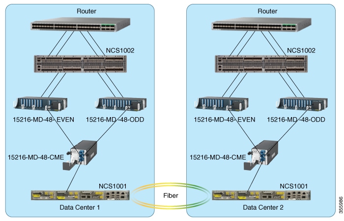
To build this topology, you:
-
Connect a router, such as Cisco CRS to NCS 1002, so that client signals, with 10G, 40G, or 100G payloads, can be transmitted from Cisco CRS to the client ports of NCS 1002.
-
Connect the trunk ports on the NCS 1002 to specific port channels on the even and odd patch panels.
-
Connect the patch panels to a splitter combiner unit which is then connected to NCS 1001.
-
Connect the NCS 1001 at both the data center locations using fiber.
This topology can be deployed using one of the following configurations.
NCS 1000 Configurations
Based on your network requirements, select the appropriate configuration.
Prerequisites
Before you build the topology, ensure to meet these prerequisites.
Prerequisites for All Configurations
-
Identify the wavelength range to use in the configuration using the Channel Wavelength Allocation table. Configure these wavelengths on the trunk ports of NCS 1002.
-
Ensure that the NCS 1002 controller is in the NSHUT state and laser is enabled on the trunk port.
-
Ensure all the EDFA ports on NCS 1001 are in the NSHUT state.
Additional Prerequisites for Protected Configuration
-
Ensure all the PSM ports on NCS 1001 are in the NSHUT state.
-
Ensure the traffic flows in the working path of the PSM module of NCS 1001.
Use the following show command to determine whether the traffic is flowing in the working or protect path.
show controllers ots 0/2/0/* summary
If traffic is on the protect path, use the following switch command to move the traffic manually from the protect to working path.
hw-module slot 2 manual-switch-to working
Additional Prerequisites for Unprotected ILA Configuration
-
Ensure that the EDFA modules are installed in both slots 1 and 3 of NCS 1001.
Unprotected Configuration
You can configure this topology to:
-
Create point-to-point connections between two data centers where protection is not required.
-
Create networks with fiber spans greater than 30 dB.
-
Create networks with short fiber spans to optimize power levels of DWDM interfaces.
Before you begin, see Prerequisites.
In this topology, the signals are transmitted in the following sequence:
-
On the near-end node, the client ports of NCS 1002 receive the 10G, 40G, or 100G client signals from the router. These client signals are transmitted as 100G, 200G, or 250G DWDM signals from the NCS 1002 trunk ports to the Cisco ONS 15216-MD-48-ODDE/Cisco ONS 15216-MD-48-EVENE patch panels.
-
The odd patch panel combines the odd wavelengths whereas the even patch panel combines the even wavelengths. The aggregated wavelengths are then transmitted to the 15216-MD-48-CME combiner/splitter.
-
The combiner/splitter combines the wavelengths and generates a composite signal.
-
The NCS1K-EDFA module receives the composite signal, amplifies, and then transmits it across the span to the NCS1K-EDFA module of the far-end node.
-
The NCS1K-EDFA module of the far-end node amplifies the signal again before sending it to the combiner/splitter.
-
The combiner/splitter splits the received composite signal into individual wavelengths before sending them to the patch panels.
-
The patch panels demultiplex the wavelengths as 100G, 200G, or 250G DWDM signals before sending them to the trunk ports of NCS 1002.
-
NCS 1002 finally transmits these signals as 10G, 40G, or 100G signals from its client ports to the customer node.
Port Connections in Unprotected Configuration
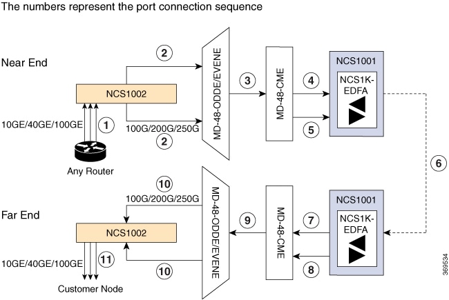
To build this topology, connect the LC/LC fibers in the following sequence as represented in Figure 2:
|
1 |
Connect an LC/LC fiber from the client ports of the router to the client ports of NCS 1002. |
|
2 |
Connect an LC/LC fiber from the NCS 1002 trunk port to MD-48-ODDE/EVENE. |
|
3 |
Connect an LC/LC fiber from the COM TX port of MD-48-ODDE/EVENE to the ODD-RX and EVEN-RX ports of MD-48-CME. |
|
4 |
Connect an LC/LC fiber from the COM-TX and COM-RX ports of MD-48-CME to the NCS 1001 EDFA slot 1 COM-RX and COM-TX ports. |
|
5 |
(Optional) When the power output is greater than 20dBm on the COM-TX port of the EDFA (pre-amplifier), connect an LC/LC fiber from the MON port of MD-48-CME to the COM-CHECK port of NCS 1001 EDFA. |
|
6 |
Connect an LC/LC fiber from NCS 1001 EDFA slot 1 LINE-TX and LINE-RX ports to NCS 1001 EDFA slot 1 LINE-RX and LINE-TX ports. |
|
7 |
Connect an LC/LC fiber from NCS 1001 EDFA slot 1 COM-TX and COM-RX ports to the COM-RX and COM-TX ports of MD-48-CME. |
|
8 |
(Optional) When the power output is greater than 20dBm on the COM-TX port of the EDFA (pre-amplifier), connect an LC/LC fiber from the COM-CHECK port of NCS 1001 EDFA to the MON port of MD-48-CME. |
|
9 |
Connect an LC/LC fiber from the ODD-RX and EVEN-RX ports of MD-48-CME to the COM TX port of MD-48-ODDE/EVENE. |
|
10 |
Connect an LC/LC fiber from MD-48-ODDE/EVENE to the NCS 1002 trunk port. |
|
11 |
Connect an LC/LC fiber from the client ports of NCS 1002 to the client ports of the customer node. |
For information on verification and troubleshooting, see Verification and General Troubleshooting.
Protected Configuration
You can configure this topology to:
-
Create connections between two data centers where protection is required using different optical paths.
Before you begin, see Prerequisites.
In this topology, the signals are transmitted in the following sequence:
-
On the near-end node, the client ports of NCS 1002 receive the 10G, 40G, or 100G client signals from the router. These client signals are transmitted as 100G, 200G, or 250G DWDM signals from the NCS 1002 trunk ports to the Cisco ONS 15216-MD-48-ODDE/Cisco ONS 15216-MD-48-EVENE patch panels.
-
The odd patch panel combines the odd wavelengths whereas the even patch panel combines the even wavelengths. The aggregated wavelengths are then transmitted to the 15216-MD-48-CME combiner/splitter.
-
The combiner/splitter combines the wavelengths and generates a composite signal.
-
The NCS1K-PSM module receives the composite signal and splits it into the working and protect path and transmits the signals to the respective NCS1K-EDFA modules.
-
The NCS1K-EDFA modules receive the composite signal, amplify, and then transmit it across the span to the NCS1K-EDFA modules of the far-end node.
-
The NCS1K-EDFA modules of the far-end node amplifiy the signal again before sending it on the working and protect path to the NCS1K-PSM module.
-
The combiner/splitter receives the composite signal from NCS1K-PSM module and splits it into individual wavelengths before sending them to the patch panels.
-
The patch panels demultiplex the wavelengths as 100G, 200G, or 250G DWDM signals before sending them to the trunk ports of NCS 1002.
-
NCS 1002 finally transmits these signals as 10G, 40G, or 100G signals from its client ports to the customer node.
Port Connections in Protected Configuration
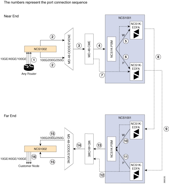
To build this topology, connect the LC/LC fibers in the following sequence as represented in Figure 3:
|
1 |
Connect an LC/LC fiber from the client ports of the router to the client ports of NCS 1002. |
|
2 |
Connect an LC/LC fiber from NCS 1002 trunk port to MD-48-ODDE/EVENE. |
|
3 |
Connect an LC/LC fiber from the COM TX port of MD-48-ODDE/EVENE to the ODD-RX and EVEN-RX ports of MD-48-CME. |
|
4 |
Connect an LC/LC fiber from the COM TX port of MD-48-CME to NCS 1001 PSM slot 2 COM-RX port. |
|
5 |
Connect an LC/LC fiber from NCS 1001 PSM slot 2 W - RX and TX ports to NCS 1001 EDFA slot 3 COM-TX and COM-RX ports. |
|
6 |
Connect an LC/LC fiber from NCS 1001 PSM slot 2 P - RX and TX ports to NCS 1001 EDFA slot 1 COM-TX and COM-RX ports. |
|
7 |
(Optional) When the power output is greater than 20dBm on the COM-TX port of the EDFA (pre-amplifier), connect a y-cable from the MON port of MD-48-CME to the COM-CHECK port of NCS 1001 EDFA slots 1 and 3. |
|
8 |
Connect an LC/LC fiber from NCS 1001 EDFA slot 3 LINE-TX and LINE-RX ports to NCS 1001 EDFA slot 3 LINE-TX and LINE-RX ports. |
|
9 |
Connect an LC/LC fiber from NCS 1001 EDFA slot 1 LINE-TX and LINE-RX ports to NCS 1001 EDFA slot 1 LINE-TX and LINE-RX ports. |
|
10 |
Connect an LC/LC fiber from NCS 1001 EDFA slot 3 COM-TX and COM-RX ports to NCS 1001 PSM slot 2 W - RX and TX ports. |
|
11 |
Connect an LC/LC fiber from NCS 1001 EDFA slot 1 COM-TX and COM-RX ports to NCS 1001 PSM slot 2 P - RX and TX ports. |
|
12 |
(Optional) When the power output is greater than 20dBm on the COM-TX port of the EDFA (pre-amplifier), connect a y-cable from the COM-CHECK port of NCS 1001 EDFA slots 1 and 3 to the MON port of MD-48-CME. |
|
13 |
Connect an LC/LC fiber from NCS 1001 PSM slot 2 COM-RX port to the COM TX port of MD-48-CME. |
|
14 |
Connect an LC/LC fiber from the ODD-RX and EVEN-RX ports of MD-48-CME to the COM TX port of MD-48-ODDE/EVENE. |
|
15 |
Connect an LC/LC fiber from MD-48-ODDE/EVENE to NCS 1002 trunk port. |
|
16 |
Connect an LC/LC fiber from the client ports of NCS 1002 to the client ports of the customer node. |
For information on verification and troubleshooting, see Verification and General Troubleshooting.
Unprotected Configuration with ILA
You can configure this topology to:
-
Create point-to-point connections between two remote nodes with distances longer than the reach of a single NCS 1001 EDFA module.
Before you begin, see Prerequisites.
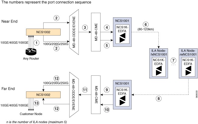
ILA nodes are used when it is not possible to connect to terminal nodes with a single span. In an ILA configuration, each span measures 80 to 120 km. A maximum of five spans is supported without the using a dynamic gain equalizer.
In this topology, the signals are transmitted in the following sequence:
-
On the near-end node, the client ports of NCS 1002 receive the 10G, 40G, or 100G client signals from the router. These client signals are transmitted as 100G, 200G, or 250G DWDM signals from the NCS 1002 trunk ports to the Cisco ONS 15216-MD-48-ODDE/Cisco ONS 15216-MD-48-EVENE patch panels.
-
The odd patch panel combines the odd wavelengths whereas the even patch panel combines the even wavelengths. The aggregated wavelengths are then transmitted to the 15216-MD-48-CME combiner/splitter.
-
The combiner/splitter combines the wavelengths and generates a composite signal.
-
The NCS1K-EDFA module receives the composite signal, amplifies, and then transmits it across the span to the ILA nodes.
-
The NCS1K-EDFA modules of the far-end node receive the composite signal from the ILA node, amplifies, and then transmits it to the combiner/splitter.
-
The combiner/splitter splits the received composite signal into individual wavelengths before sending it to the patch panels.
-
The patch panels demultiplex the wavelengths as 100G, 200G, or 250G DWDM signals before sending them to the trunk ports of NCS 1002.
-
NCS 1002 finally transmits these signals as 10G, 40G, or 100G signals from its client ports to the customer node.
Port Connections in Unprotected Configuration with ILA
To build this topology, connect the LC/LC fibers in the following sequence as represented in Figure 4:
|
1 |
Connect an LC/LC fiber from the client ports of the router to the client ports of NCS 1002. |
|
2 |
Connect an LC/LC fiber from NCS 1002 trunk port to MD-48-ODDE/EVENE. |
|
3 |
Connect an LC/LC fiber from the COM TX port of MD-48-ODDE/EVENE to the ODD-RX and EVEN-RX ports of MD-48-CME. |
|
4 |
Connect an LC/LC fiber from the COM-TX and COM-RX ports of MD-48-CME to the NCS 1001 EDFA slot 1 COM-RX and COM-TX ports. |
|
5 |
(Optional) When the power output is greater than 20dBm on the COM-TX port of the EDFA (pre-amplifier), connect an LC/LC fiber from the MON port of MD-48-CME to the COM-CHECK port of NCS 1001 EDFA. |
|
6 |
Connect an LC/LC fiber from NCS 1001 EDFA slot 1 LINE-TX and LINE-RX ports to NCS 1001 EDFA slot 1 LINE-RX and LINE-TX ports. |
|
7 |
Connect an LC/LC fiber from NCS 1001 EDFA slot 3 LINE-TX and LINE-RX ports to NCS 1001 EDFA slot 3 LINE-TX and LINE-RX ports. |
|
8 |
Connect an LC/LC fiber from NCS 1001 EDFA slot 1 LINE-TX and LINE-RX ports to NCS 1001 EDFA slot 1 LINE-TX and LINE-RX ports. |
|
9 |
Connect an LC/LC fiber from NCS 1001 EDFA slot 1 COM-TX and COM-RX ports to the COM-RX and COM-TX ports of MD-48-CME. |
|
10 |
(Optional) When the power output is greater than 20dBm on the COM-TX port of the EDFA (pre-amplifier), connect an LC/LC fiber from the COM-CHECK port of NCS 1001 EDFA to the MON port of MD-48-CME. |
|
11 |
Connect an LC/LC fiber from the ODD-RX and EVEN-RX ports of MD-48-CME to the COM TX port of MD-48-ODDE/EVENE. |
|
12 |
Connect an LC/LC fiber from MD-48-ODDE/EVENE to NCS 1002 trunk port. |
|
13 |
Connect an LC/LC fiber from the client ports of NCS 1002 to the client ports of the customer node. |
For information on verification and troubleshooting, see Verification and General Troubleshooting.
Verification
After you complete building the topology, you must verify the configuration using the following:
-
Verify all the ports do not have critical and major alarms on NCS 1001 and NCS 1002.
-
Verify the received power of the ports on NCS 1001 and NCS 1002 is within the applicable range. See the Pluggable Specifications guides for applicable power ranges.
-
Verify the thresholds of the OTS controller on NCS 1001 are within the applicable range.
-
Verify the Status LED on NCS 1002 and the SYS LED on NCS 1001 are green.
-
Verify the power utilization of NCS 1001 and NCS 1002 using the show environment power command.
NCS 1002:
sysadmin-vm:0_RP0# show environment power
Wed May  8  10:10:02.835 UTC+00:00
================================================================================
CHASSIS LEVEL POWER INFO: 0
================================================================================
   Total output power capacity (N + 1)             :    2000W +       0W
   Total output power required                     :     975W
   Total power input                               :     960W
   Total power output                              :     889W
NCS 1001:
sysadmin-vm:0_RP0# show environment power
Wed May 8 10:10:02.835 UTC+00:00 ================================================================================ CHASSIS LEVEL POWER INFO: 0 ================================================================================ Total output power capacity (N + 1) : 2000W + 2000W Total output power required : 269W Total power input : 211W Total power output : 67W -
All the three configurations are typical 96-channel systems with maximum of 2 Tbps of bandwidth. The bandwidth can be enhanced up to 24 Tbps by adding 11 additional NCS 1002 units. Verify the bandwidth using the show hw-module slice all command.
RP/0/RP0/CPU0:ios# show hw-module slice all
Thu Aug 11 16:16:58.935 IST
Slice ID:                0
Status:                  Provisioned
Client Bitrate:          100
Trunk Bitrate:           250
DP FPGA FW Type:         M100
DP FPGA FW Version:      02.00
HW Status:               CURRENT

Encryption Supported:    TRUE
Client Port -   Trunk Port     CoherentDSP0/0/0/5 and CoherentDSP0/0/0/6
Traffic Split Percentage

HundredGigECtrlr0/0/0/0                    100
HundredGigECtrlr0/0/0/1                    100
HundredGigECtrlr0/0/0/2                    100
HundredGigECtrlr0/0/0/3                    100
HundredGigECtrlr0/0/0/4                    100

Slice ID:                1
Status:                  Provisioned
Client Bitrate:          100
Trunk Bitrate:           250
DP FPGA FW Type:         M100
DP FPGA FW Version:      02.00
HW Status:               CURRENT

Encryption Supported:    TRUE
Client Port -   Trunk Port        CoherentDSP0/0/0/12 and CoherentDSP0/0/0/13
Traffic Split Percentage

HundredGigECtrlr0/0/0/7                    100
HundredGigECtrlr0/0/0/8                    100
HundredGigECtrlr0/0/0/9                    100
HundredGigECtrlr0/0/0/10                   100
HundredGigECtrlr0/0/0/11                   100

Slice ID:                2
Status:                  Provisioned
Client Bitrate:          100
Trunk Bitrate:           250
DP FPGA FW Type:         M100
DP FPGA FW Version:      02.00
HW Status:               CURRENT

Encryption Supported:    TRUE
Client Port -   Trunk Port          CoherentDSP0/0/0/19 and CoherentDSP0/0/0/20
Traffic Split Percentage

HundredGigECtrlr0/0/0/14                    100
HundredGigECtrlr0/0/0/15                    100
HundredGigECtrlr0/0/0/16                    100
HundredGigECtrlr0/0/0/17                    100
HundredGigECtrlr0/0/0/18                    100

Slice ID:                3
Status:                  Provisioned
Client Bitrate:          100
Trunk Bitrate:           250
DP FPGA FW Type:         M100
DP FPGA FW Version:      02.00
HW Status:               CURRENT

Encryption Supported:    TRUE
Client Port -   Trunk Port          CoherentDSP0/0/0/26 and CoherentDSP0/0/0/27
Traffic Split Percentage

HundredGigECtrlr0/0/0/21                    100
HundredGigECtrlr0/0/0/22                    100
HundredGigECtrlr0/0/0/23                    100
HundredGigECtrlr0/0/0/24                    100
HundredGigECtrlr0/0/0/25                    100
General Troubleshooting
When a fiber cut occurs in the network, NCS 1001 raises the RX-LOS-P or RX-LOC alarm whereas NCS 1002 raises the LOS-P alarm.
For alarm clearing procedures, see the Troubleshooting Guide for Cisco NCS 1001 and Troubleshooting Guide for Cisco NCS 1002.
You May Be Also Interested In
Solution Components
Cisco NCS 1001
Cisco NCS 1001 is a Dense Wavelength Division Multiplexing (DWDM) line system that is mechanically optimized for data center environments. The performance of NCS 1001 is optimized for maximum capacity and provides complete automation of installation and configuration with real-time and fine-grained monitoring. Cisco NCS 1001 is a 1RU system that supports up to three pluggable modules. The modules can be amplifiers, protection switch modules, or OTDR modules.
Cisco NCS 1002
Cisco NCS 1002 has an optimized footprint at 2RU and supports up to 2Tbps of client and 2Tbps of trunk traffic. It can transport 100, 200, or 250 Gbps wavelengths on the same platform through software provisioning. NCS 1002 has a software configurable modulation scheme for each slice, allowing the operator to customize the spectral efficiency and reach characteristics of individual wavelengths. NCS 1002 uses IOS XR and encompasses carrier-class software with several features such as Machine-to-Machine (M2M) APIs based on YANG data models, a streaming telemetry agent for real-time, granular device monitoring, and an infrastructure for third-party applications. Encryption of any data that leaves the data center facility becomes an important requirement for cloud operators with increasing requirements for data privacy and data protection across the globe. NCS 1002 provides AES256-based MACSec encryption for 10GE, 40GE, and 100GE clients. NCS 1002 also supports smart licensing for flexible pay-as-grow models.
Combiner and Splitter
Cisco ONS 15216-MD-48-CME is a bidirectional unit that has the MUX and the DEMUX functions implemented as two different sections. The DEMUX section includes an optical splitter to split the optical signal evenly into two different output ports: EVEN-TX port and ODD-TX port. The MUX section includes an optical combiner to combine even and odd channel signals at 100 GHz spacing (EVEN-RX and ODD-RX ports respectively) into a signal of 50 GHz channel spacing.
Multiplexer and Demultiplexer
Cisco ONS 15216-MD-48-ODDE and ONS 15216-MD-48-EVENE units are the Cisco ONS 15216 exposed faceplate multiplexer and demultiplexer patch panels of 48-channels spaced at 100 GHz on the odd or even ITU grid respectively. The patch panel enables 48 channels of ITU wavelengths to be placed or removed from a single fiber.
Key Features of Solution Components
Cisco DCI solutions run on a single operating system called Cisco IOS XR for routing, aggregation, and optical transport. Cisco IOS XR is modular so that major features are available as independent packages. Industry-standard RPMs align update and upgrade procedures with those used in the data center.
The key features of the solution components include the following:
Zero Touch Provisioning and iPXE
Instead of manual processes, device onboarding is now automated. Boot and day-zero provisioning are fast and bring devices online in minutes instead of hours. The iPXE feature supported in the Cisco IOS XR software allows an administrator to boot from TFTP, HTTP, or FTP.
YANG Data Models for Automated Provisioning
Cisco IOS XR cloud-scale features include integration with structured, data model-driven, high-performance APIs so that you can move beyond the Command Line Interface (CLI). A comprehensive set of YANG-based configuration and operational data models allows you to control the rich feature set of the OS. There is support for native, OpenConfig, and IETF models. The YANG modeling language is optimized for network devices with many tools and utilities. Encoding is decoupled from the model so that you can deploy with data encoded in JSON, XML, or Google Protocol Buffers (GPB) format. Transport is also decoupled from the choice of encoding for further flexibility. The Yang Development Kit (YDK) allows developers to generate model-driven APIs automatically from any Yang model for Python and C++.
Model-driven Telemetry for Real-time, Detailed Visibility, and Mass Awareness
End-to-end visibility into the network infrastructure is a required feature of cloud-scale networking. Until now, visibility has been limited to sections of network topologies and not available in real time to administrators. However, with the demands of a digitizing world, you need mass awareness – the ability to see what is going on in all facets of your network. Visibility must be continual and automated to support the scale and agility required today.
Cisco model-driven telemetry, available with Cisco IOS XR Software, is a new and improved approach to network monitoring. Data is streamed and captured continuously from devices with efficient and incremental updates. Model-driven telemetry can be configured using YANG models. You can specify what data to stream, to where, and with what encoding and transport using YANG models. With model-driven telemetry, you can specify the YANG model that contains the required data.
Model-driven telemetry opens up the entire operational space for fine-grained control at scale. The increased visibility provided by the push model of streaming telemetry enables the highly efficient techniques of segment routing for real-time network optimization.
Related Documentation
Use this guide with the following referenced publications for prerequisites, constraints, limitations, and troubleshooting tips.
-
Hardware Installation Guide for Cisco NCS 1002
-
System Setup and Software Installation Guide for Cisco NCS 1002
-
Configuration Guide for Cisco NCS 1002
-
Troubleshooting Guide for Cisco NCS 1002
-
Hardware Installation Guide for Cisco NCS 1001
-
Configuration Guide for Cisco NCS 1001
-
Troubleshooting Guide for Cisco NCS 1001
-
Installing the Cisco ONS 15216-MD-48-CM Interleaver and Deinterleaver Pluggable and Cisco ONS 15216-MD-48-CME Coupler and Splitter Pluggable
-
Installing the Cisco ONS 15216-MD-48-ODD/15216-MD-48-ODDE and 15216-MD-48-EVEN/15216-MD-48-EVENE Mux/Demux Patch Panels
Communications, Services, and Additional Information
-
To receive timely, relevant information from Cisco, sign up at Cisco Profile Manager.
-
To get the business impact you’re looking for with the technologies that matter, visit Cisco Services.
-
To submit a service request, visit Cisco Support.
-
To discover and browse secure, validated enterprise-class apps, products, solutions and services, visit Cisco DevNet.
-
To obtain general networking, training, and certification titles, visit Cisco Press.
-
To find warranty information for a specific product or product family, access Cisco Warranty Finder.
Cisco Bug Search Tool
Cisco Bug Search Tool (BST) is a web-based tool that acts as a gateway to the Cisco bug tracking system that maintains a comprehensive list of defects and vulnerabilities in Cisco products and software. BST provides you with detailed defect information about your products and software.
 Feedback