- Preface
- Cisco ONS Documentation Roadmap for Release 9.4
- Chapter 1, Install the Cisco ONS 15454, ONS 15454 M2, and ONS 15454 M6 Shelf
- Chapter 2, Connecting the PC and Logging into the GUI
- Chapter 3, Install the Control Cards
- Chapter 4, Setup Optical Service Channel Cards
- Chapter 5, Optical Amplifier Cards
- Chapter 6, Provision Multiplexer and Demultiplexer Cards
- Chapter 7, Setup Tunable Dispersion Compensating Units
- Chapter 8, Provision Protection Switching Module
- Chapter 9, Optical Add/Drop Cards
- Chapter 10, Reconfigurable Optical Add/Drop Cards
- Chapter 11, Provision Transponder and Muxponder Cards
- Chapter 12, Node Reference
- Chapter 13, Network Reference
- Chapter 14, Turn Up a Node
- Chapter 15, Perform Node Acceptance Tests
- Chapter 16, Turn Up a Network
- Chapter 17, Create Optical Channel Circuits and Provisionable Patchcords
- Chapter 18, Monitor Performance
- Chapter 19, Manage the Node
- Chapter 20, Alarm and TCA Monitoring and Management
- Chapter 21, Change DWDM Card Settings
- Chapter 22, Manage Network Connectivity
- Chapter 23, Upgrade, Add, and Remove Cards and Nodes
- Chapter 24, Maintain the Node
- Chapter 25, Security Reference
- Chapter 26, Timing Reference
- Chapter 27, SNMP
- Appendix A, CTC Operation, Information, and Shortcuts
- Appendix B, Hardware Specifications
- Appendix C, Administrative and Service States
- Appendix D, Configure GE_XP, 10GE_XP, GE_XPE, and 10GE_XPE Cards Using PCLI
- Appendix E, Pseudo Command Line Interface Reference
- Appendix F, Fiber and Connector Losses in Raman Link Configuration
- Appendix G, Card Features
- Appendix H, Network Element Defaults
Setup Optical Service Channel Cards
This chapter describes the optical service channel (OSC) cards for Cisco ONS 15454 dense wavelength division multiplexing (DWDM) networks. For card safety and compliance information, refer to the Regulatory Compliance and Safety Information for Cisco CPT and Cisco ONS Platforms document.

Note![]() Unless noted otherwise, the cards described in this chapter are supported on the Cisco ONS 15454, Cisco ONS 15454 M6, Cisco ONS 15454 M2 platforms.
Unless noted otherwise, the cards described in this chapter are supported on the Cisco ONS 15454, Cisco ONS 15454 M6, Cisco ONS 15454 M2 platforms.
Note![]() Unless otherwise specified, “ONS 15454” refers to both ANSI and ETSI shelf assemblies.
Unless otherwise specified, “ONS 15454” refers to both ANSI and ETSI shelf assemblies.
4.1 Card Overview
This section provides card summary and compatibility information.
Note![]() Each card is marked with a symbol that corresponds to a slot (or slots) on the ONS 15454 shelf assembly. The cards are then installed into slots displaying the same symbols. For a list of slots and symbols, see the “Card Slot Requirements” section in the Cisco ONS 15454 Hardware Installation Guide.
Each card is marked with a symbol that corresponds to a slot (or slots) on the ONS 15454 shelf assembly. The cards are then installed into slots displaying the same symbols. For a list of slots and symbols, see the “Card Slot Requirements” section in the Cisco ONS 15454 Hardware Installation Guide.
An optical service channel (OSC) is a bidirectional channel connecting two adjacent nodes in a DWDM ring. For every DWDM node (except terminal nodes), two different OSC terminations are present, one for the west side and another for the east side. The channel transports OSC overhead that is used to manage ONS 15454 DWDM networks. An OSC signal uses the 1510-nm wavelength and does not affect client traffic. The primary purpose of this channel is to carry clock synchronization and orderwire channel communications for the DWDM network. It also provides transparent links between each node in the network. The OSC is an OC-3/STM-1 formatted signal.
There are two versions of the OSC modules: the OSCM, and the OSC-CSM, which contains the OSC wavelength combiner and separator component in addition to the OSC module.
The Mesh/Multiring Upgrade (MMU) card is used to optically bypass a given wavelength from one section of the network or ring to another one without requiring 3R regeneration.
Note![]() On 15454-M2 and 15454-M6 shelves, the TNC and TNCE cards include the functions of the OSCM card. OSC can be created on the OC3 port (SFP-0) of the TNC and TNCE cards.
On 15454-M2 and 15454-M6 shelves, the TNC and TNCE cards include the functions of the OSCM card. OSC can be created on the OC3 port (SFP-0) of the TNC and TNCE cards.
The TNC and TNCE cards support two optical service channels (OSC): primary OSC and secondary OSC.
The primary optical service channel (SFP-0) supports the following interfaces:
The secondary optical service channel (SFP-1) supports the following interfaces:
4.1.1 Card Summary
Table 4-1 lists and summarizes the functions of each card.
|
|
|
|
|---|---|---|
|
|
The OSCM has one set of optical ports and one Ethernet port located on the faceplate. It operates in Slots 8 and 10. |
See the “OSCM Card” section. |
|
|
The OSC-CSM has three sets of optical ports and one Ethernet port located on the faceplate. It operates in Slots 1 to 6 and 12 to 17. |
See the “OSC-CSM Card” section. |
4.1.2 Card Compatibility
Table 4-2 lists the CTC software compatibility for the OSC and OSCM cards.
|
|
|
|
|
|
|
|
|
|
|
|
|
|
|
|
|
|---|---|---|---|---|---|---|---|---|---|---|---|---|---|---|---|
4.2 Class 1 Laser Safety Labels
For information about safety labels, see the “Safety Labels” section.
4.3 OSCM Card
Note![]() For OSCM card specifications, see the OSCM Card Specifications document.
For OSCM card specifications, see the OSCM Card Specifications document.
Note![]() On 15454-M2 and 15454-M6 shelves, the TNC and TNCE cards include the functions of the OSCM card.
On 15454-M2 and 15454-M6 shelves, the TNC and TNCE cards include the functions of the OSCM card.
The OSCM card is used in amplified nodes that include the OPT-BST, OPT-BST-E, or OPT-BST-L booster amplifier. The OPT-BST, OPT-BST-E, and OPT-BST-L cards include the required OSC wavelength combiner and separator component. The OSCM cannot be used in nodes where you use OC-N/STM-N cards, electrical cards, or cross-connect cards. The OSCM uses Slots 8 and 10, which are also cross-connect card slots.
The OSCM supports the following features:
- OC-3/STM-1 formatted OSC
- Supervisory data channel (SDC) forwarded to the TCC2/TCC2P/TCC3 cards for processing
- Distribution of the synchronous clock to all nodes in the ring
- 100BaseT far-end (FE) User Channel (UC)
- Monitoring functions such as orderwire support and optical safety
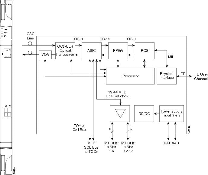
The OC-3/STM-1 section data communications channel (SDCC or RS-DCC) overhead bytes are used for network communications. An optical transceiver terminates the OC-3/STM-1, then it is regenerated and converted into an electrical signal. The SDCC or RS-DCC bytes are forwarded to the active and standby TCC2/TCC2P/TCC3 cards for processing through the system communication link (SCL) bus on the backplane. Orderwire bytes (E1, E2, F1) are also forwarded via the SCL bus to the TCC2/TCC2P/TCC3 for forwarding to the AIC-I card.
The payload portion of the OC-3/STM-1 is used to carry the fast Ethernet UC. The frame is sent to a packet-over-SONET/SDH (POS) processing block that extracts the Ethernet packets and makes them available at the RJ-45 connector.
The OSCM distributes the reference clock information by removing it from the incoming OC-3/STM-1 signal and then sending it to the DWDM cards. The DWDM cards then forward the clock information to the active and standby TCC2/TCC2P/TCC3 cards.
4.3.1 Faceplate and Block Diagram
Figure 4-1 shows the OSCM card faceplate and block diagram.
Figure 4-1 OSCM Card Faceplate
For information on safety labels for the card, see the “Class 1 Laser Safety Labels” section.
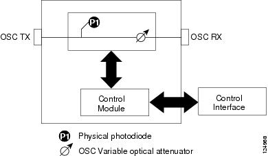
Figure 4-2 shows the block diagram of the variable optical attenuator (VOA) within the OSCM.
The OSCM has one OC-3/STM-1 optical port located on the faceplate. One long-reach OSC transmits and receives the OSC to and from another DWDM node. Both DCN data and FE payload are carried on this link.
Figure 4-2 OSCM VOA Optical Module Functional Block Diagram
4.3.2 OSCM Card Functions
The functions of the OSCM card are:
- OSCM Card Power Monitoring
- Card level indicators—Table G-5
- Port-Level Indicators
4.3.2.1 OSCM Card Power Monitoring
Physical photodiode P1 monitors the power for the OSCM card. The returned power level value is calibrated to the OSC TX port ( Table 4-3 ).
|
|
|
|
|---|---|---|
For information on the associated TL1 AIDs for the optical power monitoring points, refer the “CTC Port Numbers and TL1 Aids” section in Cisco ONS SONET TL1 Command Guide.
4.3.3 Related Procedures for the OSCM Card
The following is the list of procedures and tasks related to the configuration of the OSCM card:
- G39 Verify OSCM Transmit Power
- G45 Perform the C-Band and L-Band Line Amplifier Node with OSCM Cards Acceptance Test
- G47 Perform the C-Band Line Amplifier Node with OSCM and OSC-CSM Cards Acceptance Test
- G157 Perform the L-Band Line Amplifier Node with OSCM and OSC-CSM Cards Acceptance Test
- G48 Perform the OADM Node Acceptance Test on a Symmetric Node with OSCM Cards
- G93 Verify Add and Drop Connections on an OADM Node with OSCM Cards
- DLP-G139 View PM Parameters for OSCM and OSC-CSM cards
- G90 Modify OSCM and OSC-CSM Card Line Settings and PM Thresholds
4.4 OSC-CSM Card
Note![]() For OSC-CSM card specifications, see the OSC-CSM Card Specifications document.
For OSC-CSM card specifications, see the OSC-CSM Card Specifications document.
The OSC-CSM card is used in unamplified nodes. This means that the booster amplifier with the OSC wavelength combiner and separator is not required for OSC-CSM operation. The OSC-CSM can be installed in Slots 1 to 6 and 12 to 17. To operate in hybrid mode, the OSC-CSM cards must be accompanied by cross-connect cards. The cross-connect cards enable functionality on the OC-N/STM-N cards and electrical cards.
The OSC-CSM supports the following features:
- Optical combiner and separator module for multiplexing and demultiplexing the optical service channel to or from the wavelength division multiplexing (WDM) signal
- OC-3/STM-1 formatted OSC
- SDC forwarded to the TCC2/TCC2P/TCC3 cards for processing
- Distribution of the synchronous clock to all nodes in the ring
- 100BaseT FE UC
- Monitoring functions such as orderwire support
- Optical safety: Signal loss detection and alarming, fast transmitted power shut down by means of an optical 1x1 switch
- Optical safety remote interlock (OSRI), a feature capable of shutting down the optical output power
- Automatic laser shutdown (ALS), a safety mechanism used in the event of a fiber cut. For details on ALS provisioning for the card, see the G203 Change the OSCM and OSC-CSM ALS Maintenance Settings. For information on using the card to implement ALS in a network, see the “Network Optical Safety” section.
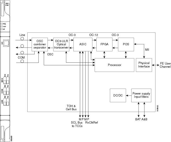
The WDM signal coming from the line is passed through the OSC combiner and separator, where the OSC signal is extracted from the WDM signal. The WDM signal is sent along with the remaining channels to the COM port (label on the front panel) for routing to the OADM or amplifier units, while the OSC signal is sent to an optical transceiver.
The OSC is an OC-3/STM-1 formatted signal. The OC-3/STM-1 SDCC or RS-DCC overhead bytes are used for network communications. An optical transceiver terminates the OC-3/STM-1, and then it is regenerated and converted into an electrical signal. The SDCC or RS-DCC bytes are forwarded to the active and standby TCC2/TCC2P/TCC3 cards for processing via the SCL bus on the backplane. Orderwire bytes (E1, E2, F1) are also forwarded via the SCL bus to the TCC2/TCC2P/TCC3 for forwarding to the AIC-I card.
The payload portion of the OC-3/STM-1 is used to carry the fast Ethernet UC. The frame is sent to a POS processing block that extracts the Ethernet packets and makes them available at the RJ-45 front panel connector.
The OSC-CSM distributes the reference clock information by removing it from the incoming OC-3/STM-1 signal and then sending it to the active and standby TCC2/TCC2P/TCC3 cards. The clock distribution is different from the OSCM card because the OSC-CSM does not use Slot 8 or 10 (cross-connect card slots).
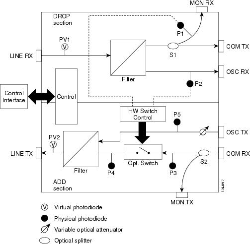
Note![]() S1 and S2 (Figure 4-5) are optical splitters with a splitter ratio of 2:98. The result is that the power at the MON TX port is about 17 dB lower than the relevant power at the COM RX port, and the power at the MON RX port is about 20 dB lower than the power at the COM TX port. The difference is due to the presence of a tap coupler for the P1 photodiode.
S1 and S2 (Figure 4-5) are optical splitters with a splitter ratio of 2:98. The result is that the power at the MON TX port is about 17 dB lower than the relevant power at the COM RX port, and the power at the MON RX port is about 20 dB lower than the power at the COM TX port. The difference is due to the presence of a tap coupler for the P1 photodiode.
4.4.1 Faceplate and Block Diagram
Figure 4-3 shows the OSC-CSM faceplate.
For information on safety labels for the card, see the “Class 1 Laser Safety Labels” section.
The OSC-CSM has a OC3 port and three other sets of ports located on the faceplate.
Figure 4-4 shows a block diagram of the OSC-CSM card.
Figure 4-4 OSC-CSM Block Diagram
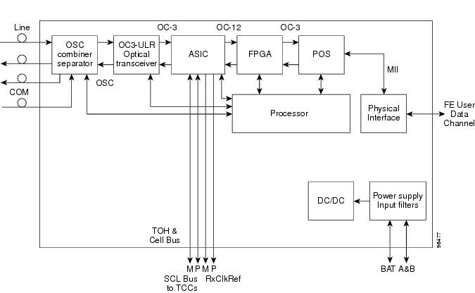
Figure 4-5 shows the OSC-CSM optical module functional block diagram.
Figure 4-5 OSC-CSM Optical Module Functional Block Diagram
4.4.2 OSC-CSM Card Functions
The functions of the OSC-CSM card are:
- OSC-CSM Card Power Monitoring
- Alarms and Thresholds
- Card level indicators—Table G-5
- Port-Level Indicators
4.4.2.1 OSC-CSM Card Power Monitoring
Physical photodiodes P1, P2, P3, and P5 monitor the power for the OSC-CSM card. Their function is as follows:
- P1: The returned power value is calibrated to the LINE RX port, including the insertion loss of the previous filter (the reading of this power dynamic range has been brought backward towards the LINE RX output).
- P2: The returned value is calibrated to the LINE RX port.
- P3: The returned value is calibrated to the COM RX port.
- P5: The returned value is calibrated to the OSC TX port, including the insertion loss of the subsequent filter.
The returned power level values are calibrated to the ports as shown in Table 4-4 .
|
|
|
|
|
|
|---|---|---|---|---|
The OSC power on the LINE TX is the same as the power reported from P5.
The PM parameters for the power values are listed in the Optics and 8b10b PM Parameter Definitions document.
For information on the associated TL1 AIDs for the optical power monitoring points, refer the “CTC Port Numbers and TL1 Aids” section in Cisco ONS SONET TL1 Command Guide.
4.4.3 Related Procedures for the OSC-CSM Card
The following is the list of procedures and tasks related to the configuration of the OSC-CSM card:
- G46 Perform the C-Band Line Amplifier Node with OSC-CSM Cards Acceptance Test
- G156 Perform the L-Band Line Amplifier Node with OSC-CSM Cards Acceptance Test
- G47 Perform the C-Band Line Amplifier Node with OSCM and OSC-CSM Cards Acceptance Test
- G157 Perform the L-Band Line Amplifier Node with OSCM and OSC-CSM Cards Acceptance Test
- G49 Perform the Active OADM Node Acceptance Test on a Symmetric Node with OSC-CSM Cards
- G50 Perform the Passive OADM Node Acceptance Test on a Symmetric Node with OSC-CSM Cards
- DLP-G139 View PM Parameters for OSCM and OSC-CSM cards
- G90 Modify OSCM and OSC-CSM Card Line Settings and PM Thresholds
 Feedback