- Preface
- Cisco ONS Documentation Roadmap for Release 9.4
- Chapter 1, Install the Cisco ONS 15454, ONS 15454 M2, and ONS 15454 M6 Shelf
- Chapter 2, Connecting the PC and Logging into the GUI
- Chapter 3, Install the Control Cards
- Chapter 4, Setup Optical Service Channel Cards
- Chapter 5, Optical Amplifier Cards
- Chapter 6, Provision Multiplexer and Demultiplexer Cards
- Chapter 7, Setup Tunable Dispersion Compensating Units
- Chapter 8, Provision Protection Switching Module
- Chapter 9, Optical Add/Drop Cards
- Chapter 10, Reconfigurable Optical Add/Drop Cards
- Chapter 11, Provision Transponder and Muxponder Cards
- Chapter 12, Node Reference
- Chapter 13, Network Reference
- Chapter 14, Turn Up a Node
- Chapter 15, Perform Node Acceptance Tests
- Chapter 16, Turn Up a Network
- Chapter 17, Create Optical Channel Circuits and Provisionable Patchcords
- Chapter 18, Monitor Performance
- Chapter 19, Manage the Node
- Chapter 20, Alarm and TCA Monitoring and Management
- Chapter 21, Change DWDM Card Settings
- Chapter 22, Manage Network Connectivity
- Chapter 23, Upgrade, Add, and Remove Cards and Nodes
- Chapter 24, Maintain the Node
- Chapter 25, Security Reference
- Chapter 26, Timing Reference
- Chapter 27, SNMP
- Appendix A, CTC Operation, Information, and Shortcuts
- Appendix B, Hardware Specifications
- Appendix C, Administrative and Service States
- Appendix D, Configure GE_XP, 10GE_XP, GE_XPE, and 10GE_XPE Cards Using PCLI
- Appendix E, Pseudo Command Line Interface Reference
- Appendix F, Fiber and Connector Losses in Raman Link Configuration
- Appendix G, Card Features
- Appendix H, Network Element Defaults
- 3.1 Card Overview
- 3.2 Safety Labels
- 3.3 TCC2 Card
- 3.4 TCC2P Card
- 3.5 TCC3 Card
- 3.6 TNC and TNCE Card
- 3.7 TSC and TSCE Cards
- 3.8 Digital Image Signing
- 3.9 AIC-I Card
- 3.10 MS-ISC-100T Card
- 3.11 Front Mount Electrical Connections
- 3.12 Procedures for Control Cards
- NTP-G278 Upgrade the TSC Card to the TNC Card
Install the Control Cards

Note![]() The terms “Unidirectional Path Switched Ring” and “UPSR” may appear in Cisco literature. These terms do not refer to using Cisco ONS 15xxx products in a unidirectional path switched ring configuration. Rather, these terms, as well as “Path Protected Mesh Network” and “PPMN”, refer generally to Cisco's path protection feature, which may be used in any topological network configuration. Cisco does not recommend using its path protection feature in any particular topological network configuration.
The terms “Unidirectional Path Switched Ring” and “UPSR” may appear in Cisco literature. These terms do not refer to using Cisco ONS 15xxx products in a unidirectional path switched ring configuration. Rather, these terms, as well as “Path Protected Mesh Network” and “PPMN”, refer generally to Cisco's path protection feature, which may be used in any topological network configuration. Cisco does not recommend using its path protection feature in any particular topological network configuration.
This chapter describes the common-control cards needed for the Cisco ONS 15454, Cisco ONS 15454 M2, and Cisco ONS 15454 M6 platforms and provides installation and card turn up procedures.
For card safety and compliance information, refer to the Regulatory Compliance and Safety Information for Cisco CPT and Cisco ONS Platforms document.
Note![]() Unless otherwise specified, “ONS 15454” refers to both ANSI and ETSI shelf assemblies.
Unless otherwise specified, “ONS 15454” refers to both ANSI and ETSI shelf assemblies.
Note![]() The cards described in this chapter are supported on the Cisco ONS 15454, Cisco ONS 15454 M6, Cisco ONS 15454 M2 platforms, unless noted otherwise.
The cards described in this chapter are supported on the Cisco ONS 15454, Cisco ONS 15454 M6, Cisco ONS 15454 M2 platforms, unless noted otherwise.
- Card Overview
- TCC2 Card
- “Related Procedures for TCC2 Card” section
- TCC2P Card
- “Related Procedures for TCC2P Card” section
- TCC3 Card
- Related Procedures for TCC3 Card
- TNC and TNCE Card
- Related Procedures for TNC and TNCE Cards
- TSC and TSCE Cards
- Related Procedures for TSC and TSCE Cards
- Digital Image Signing
- Related Procedures for DIS
- AIC-I Card
- Related Procedures for AIC-I Card
- MS-ISC-100T Card
- Related Procedures for MS-ISC-100T Card
- Front Mount Electrical Connections
- Procedures for Control Cards
3.1 Card Overview
The card overview section lists the cards described in this chapter.
Each card is marked with a symbol that corresponds to a slot (or slots) on the ONS 15454 shelf assembly. The cards are then installed into slots displaying the same symbols. For a list of slots and symbols, see the “Card Slot Requirements” section in the Cisco ONS 15454 Hardware Installation Guide.
3.1.1 Common Control Cards
The following common control cards are needed to support the functions of the DWDM, transponder, and muxponder cards on ONS 15454 shelf:
The TNC, TNCE, TSC, and TSCE cards are used to support the functions of DWDM, transponder, and muxponder cards on the Cisco ONS 15454 M2 and Cisco ONS 15454 M6 shelves.
3.1.2 Card Compatibility
Table 3-1 lists the platform and software release compatibility for the control cards.
|
|
|
|
|
|
|
|
|
|
|
|---|---|---|---|---|---|---|---|---|---|
|
|
|||||||||
|
|
|||||||||
|
|
|||||||||
|
|
|||||||||
|
|
|||||||||
|
|
|||||||||
|
|
|||||||||
|
|
|||||||||
|
|
|||||||||
|
|
|||||||||
|
|
|||||||||
|
|
|||||||||
|
|
|||||||||
|
|
|||||||||
|
|
|||||||||
|
|
15454-M2 and 15454-M62 |
3.1.3 Front Mount Electrical Connections (ETSI only)
The following Front Mount Electrical Connections (FMECs) are needed to support the functions of the DWDM, transponder, and muxponder cards:
3.2 Safety Labels
For information about safety labels, see the “Safety Labels” section.
3.3 TCC2 Card
Note![]() For TCC2 card specifications, see the “TCC2 Card Specifications” section in the Hardware Specifications document.
For TCC2 card specifications, see the “TCC2 Card Specifications” section in the Hardware Specifications document.
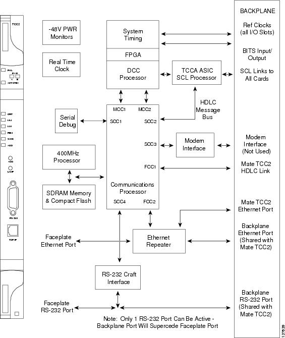
The Advanced Timing, Communications, and Control (TCC2) card performs system initialization, provisioning, alarm reporting, maintenance, diagnostics, IP address detection/resolution, SONET section overhead (SOH) data communications channel/generic communications channel (DCC/GCC) termination, optical service channel (OSC) DWDM data communications network (DCN) termination, and system fault detection for the ONS 15454. The TCC2 also ensures that the system maintains Stratum 3 (Telcordia GR-253-CORE) timing requirements. It monitors the supply voltage of the system.
Note![]() The LAN interface of the TCC2 card meets the standard Ethernet specifications by supporting a cable length of 328 ft. (100 m) at temperatures from 32 to 149 degrees Fahrenheit (0 to 65 degrees Celsius).
The LAN interface of the TCC2 card meets the standard Ethernet specifications by supporting a cable length of 328 ft. (100 m) at temperatures from 32 to 149 degrees Fahrenheit (0 to 65 degrees Celsius).
Install TCC2 cards in Slots 7 and 11 for redundancy. If the active TCC2 fails, traffic switches to the protect TCC2.
3.3.1 Faceplate and Block Diagram
Figure 3-1 shows the faceplate and block diagram for the TCC2 card.
Figure 3-1 TCC2 Faceplate and Block Diagram
3.3.2 TCC2 Card Functions
The functions of the TCC2 card are:
- Communication and Control for Controller Cards
- Timing Synchronization
- Interface Ports
- Redundant Controller Card Installation
- Card level indicators—Table G-1
- Network level indicators—Table G-13
3.3.3 Related Procedures for TCC2 Card
The following is the list of procedures and tasks related to the configuration of the TCC2 card:
- G15 Install the Common Control Cards
- NTP-G18 Set Up CTC Computer for Local Craft Connection to the ONS 15454
- NTP-G17 Set Up Computer for CTC
- G22 Verify Common Card Installation
- G144 Provision a Multishelf Node
- G25 Set Battery Power Monitor Thresholds
- G26 Set Up CTC Network Access
- G143 Import the Cisco Transport Planner NE Update Configuration File
- G163 Upgrade Nodes in Single-Shelf Mode to Multishelf Mode
- G51 Verify DWDM Node Turn Up
- NTP-G81 Change CTC Network Access
- NTP-G146 Add a Rack, Passive Unit, or Shelf to a Multishelf Node
- NTP-G147 Delete a Passive Unit, Shelf, or Rack from a Multishelf Node
- G103 Back Up the Database
- G104 Restore the Database
- G106 Reset Cards Using CTC
- G105 Restore the Node to Factory Configuration
3.4 TCC2P Card
Note![]() For TCC2P card specifications, see the”TCC2P Card Specifications” section in the Hardware Specifications document.
For TCC2P card specifications, see the”TCC2P Card Specifications” section in the Hardware Specifications document.
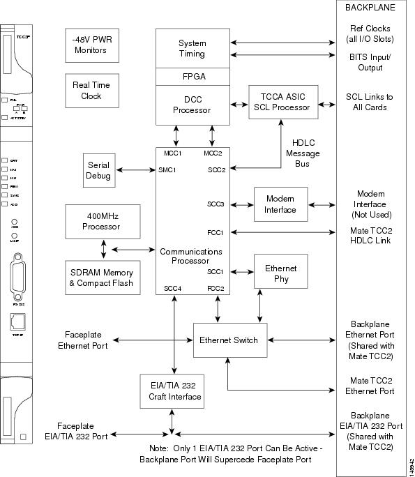
The Advanced Timing, Communications, and Control Plus (TCC2P) card is an enhanced version of the TCC2 card. The primary enhancements are Ethernet security features and 64K composite clock BITS timing.
The TCC2P card performs system initialization, provisioning, alarm reporting, maintenance, diagnostics, IP address detection/resolution, SONET SOH DCC/GCC termination, and system fault detection for the ONS 15454. The TCC2P also ensures that the system maintains Stratum 3 (Telcordia GR-253-CORE) timing requirements. It monitors the supply voltage of the system.
The TCC2P card supports multi-shelf management. The TCC2P card acts as a shelf controller and node controller for the ONS 15454. The TCC2P card supports up to four subtended shelves through the MS-ISC card or external switch. In a multi-shelf configuration, the TCC2P card allows the ONS 15454 node to be a node controller and does not support subtending of ONS 15454 M6 shelves.
The TCC2P card is compliant to the following standards:
- The LAN interface of the TCC2P card meets the standard Ethernet specifications by supporting a cable length of 328 ft. (100 m) at temperatures from 32 to 149 degrees Fahrenheit (0 to 65 degrees Celsius). The interfaces can operate with a cable length of 32.8 ft. (10 m) maximum at temperatures from –40 to 32 degrees Fahrenheit (–40 to 0 degrees Celsius).
- The TCC2P card is Restriction of Use of Hazardous Substances (RoHS) complaint. The RoHS regulations limit or ban the specific substances such as lead, cadmium, polybrominated biphenyl (PBB), mercury, hexavalent chromium, and polybrominated diphenyl ether (PBDE) flame retardants in a new electronic and electric equipment.
Install TCC2P cards in Slots 7 and 11 for redundancy. If the active TCC2P card fails, traffic switches to the protect TCC2P card. All TCC2P card protection switches conform to protection switching standards when the bit error rate (BER) counts are not in excess of 1 * 10 exp – 3 and completion time is less than 50 ms.
3.4.1 Faceplate and Block Diagram
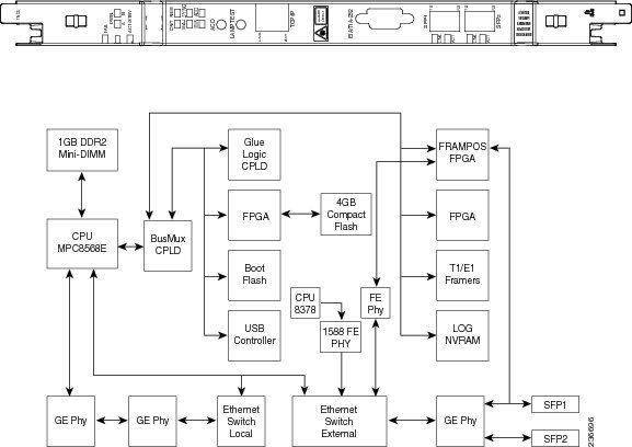
Figure 3-2 shows the faceplate and block diagram for the TCC2P card.
Figure 3-2 TCC2P Faceplate and Block Diagram
3.4.2 TCC2P Card Functions
The functions of the TCC2P card are:
- Communication and Control for Controller Cards
- Timing Synchronization
- Interface Ports
- Database Storage
- Redundant Controller Card Installation
- Card level indicators—Table G-1 l
- Network level indicators—Table G-13
- Power level indicators—Table G-11
3.4.3 Related Procedures for TCC2P Card
The following is the list of procedures and tasks related to the configuration of the TCC2P card:
- G15 Install the Common Control Cards
- NTP-G18 Set Up CTC Computer for Local Craft Connection to the ONS 15454
- NTP-G17 Set Up Computer for CTC
- DLP-G43 Disable or Bypass Proxy Service Using Internet Explorer (Windows)
- DLP-G44 Disable or Bypass Proxy Service Using Mozilla (Solaris)
- DLP-G48 Create Login Node Groups
- DLP-G49 Add a Node to the Current Session or Login Group
- G22 Verify Common Card Installation
- G144 Provision a Multishelf Node
- G25 Set Battery Power Monitor Thresholds
- G26 Set Up CTC Network Access
- G143 Import the Cisco Transport Planner NE Update Configuration File
- G163 Upgrade Nodes in Single-Shelf Mode to Multishelf Mode
- G51 Verify DWDM Node Turn Up
- NTP-G81 Change CTC Network Access
- NTP-G146 Add a Rack, Passive Unit, or Shelf to a Multishelf Node
- NTP-G147 Delete a Passive Unit, Shelf, or Rack from a Multishelf Node
- G103 Back Up the Database
- G104 Restore the Database
- G106 Reset Cards Using CTC
- G105 Restore the Node to Factory Configuration
3.5 TCC3 Card
Note![]() For TCC3 card specifications, see the “TCC3 Card Specifications” section in the Hardware Specifications document.
For TCC3 card specifications, see the “TCC3 Card Specifications” section in the Hardware Specifications document.
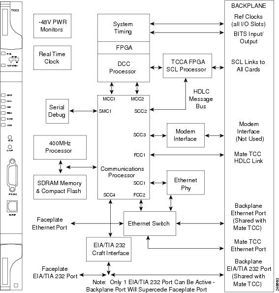
The Timing Communications Control Three (TCC3) card is an enhanced version of the TCC2P card. The primary enhancements include the increase in memory size and compact flash space. The TCC3 card boots up as TCC2P card in older releases and as TCC3 card from Release 9.2 onwards.
The TCC3 card performs system initialization, provisioning, alarm reporting, maintenance, diagnostics, IP address detection/resolution, SONET SOH DCC/GCC termination, and system fault detection for the ONS 15454. The TCC3 also ensures that the system maintains Stratum 3 (Telcordia GR-253-CORE) timing requirements. It monitors the supply voltage of the system.
The TCC3 card supports multi-shelf management. The TCC3 card acts as a shelf controller and node controller for the ONS 15454. The TCC3 card supports up to 30 subtended shelves through the MSM-ISC card or external switch. In a multi-shelf configuration, the TCC3 card allows the ONS 15454 node to be a node controller if an M6 shelf is subtended to it. We recommend the use of TCC3 card as a node controller when the number of subtended shelves exceeds four.
The TCC3 card is compliant with the following standards:
- The LAN interface of the TCC3 card meets the standard Ethernet specifications by supporting a cable length of 328 ft (100 m) at temperatures ranging from 32 to 149 degrees Fahrenheit (0 to 65 degrees Celsius). The interfaces can operate with a cable length of 32.8 ft (10 m) maximum at temperatures from –40 to 32 degrees Fahrenheit (–40 to 0 degrees Celsius).
- The TCC3 card is Restriction of Use of Hazardous Substances (RoHS) compliant. The RoHS regulations limit or ban the specific substances such as lead, cadmium, polybrominated biphenyl (PBB), mercury, hexavalent chromium, and polybrominated diphenyl ether (PBDE) flame retardants in a new electronic and electric equipment.
3.5.1 Faceplate and Block Diagram
Figure 3-3 shows the faceplate and block diagram for the TCC3 card.
Figure 3-3 TCC3 Faceplate and Block Diagram
3.5.2 TCC3 Card Functions
The functions of the TCC3 card are:
- Communication and Control for Controller Cards
- Timing Synchronization
- Interface Ports
- Database Storage
- Redundant Controller Card Installation
- Card level indicators—Table G-1
- Network level indicators—Table G-13
- Power level indicators—Table G-12
3.5.3 Related Procedures for TCC3 Card
The following is the list of procedures and tasks related to the configuration of the TCC3 card:
- G15 Install the Common Control Cards
- NTP-G18 Set Up CTC Computer for Local Craft Connection to the ONS 15454
- NTP-G17 Set Up Computer for CTC
- DLP-G43 Disable or Bypass Proxy Service Using Internet Explorer (Windows)
- DLP-G44 Disable or Bypass Proxy Service Using Mozilla (Solaris)
- DLP-G48 Create Login Node Groups
- DLP-G49 Add a Node to the Current Session or Login Group
- G22 Verify Common Card Installation
- G144 Provision a Multishelf Node
- G25 Set Battery Power Monitor Thresholds
- G26 Set Up CTC Network Access
- G143 Import the Cisco Transport Planner NE Update Configuration File
- G163 Upgrade Nodes in Single-Shelf Mode to Multishelf Mode
- G51 Verify DWDM Node Turn Up
- NTP-G81 Change CTC Network Access
- NTP-G146 Add a Rack, Passive Unit, or Shelf to a Multishelf Node
- NTP-G147 Delete a Passive Unit, Shelf, or Rack from a Multishelf Node
- G103 Back Up the Database
- G104 Restore the Database
- G106 Reset Cards Using CTC
- G105 Restore the Node to Factory Configuration
3.6 TNC and TNCE Card
(Cisco ONS 15454 M2 and ONS 15454 M6 only)
The TNC and TNCE cards combine the functions of multiple cards such as TCC2P, OSCM, ISC, and AIC-I cards. The card has a similar look and feel to TCC2/TCC2P/TCC3 cards.
Note![]() For TNC and TNCE card specifications, see the “TNC and TNCE Card Specifications (Cisco ONS 15454 M2 and Cisco ONS 15454 M6)” section in the Hardware Specifications document.
For TNC and TNCE card specifications, see the “TNC and TNCE Card Specifications (Cisco ONS 15454 M2 and Cisco ONS 15454 M6)” section in the Hardware Specifications document.
The TNC and TNCE cards are provisioned as master and slave in the 15454-M6 shelf, and as a stand-alone card in the 15454-M2 shelf. The TNC and TNCE cards serve as the processor card for the node.
On the 15454-M6 shelf, install redundant TNC and TNCE cards in slots 1 and 8. If the active TNC or TNCE card fails, system traffic switches to the redundant TNC or TNCE card. The card supports line cards from slots 2 to 7.
On the 15454-M2 shelf, install the stand-alone TNC and TNCE cards in slot 1. The TNC and TNCE cards support line cards in slots 2 and 3.
The TNC and TNCE cards monitor both the supply voltage inputs on the 15454-M6 shelf. The TNC and TNCE cards raise an alarm if one of the supply voltage inputs has a voltage out of the specified range. The 15454-M2 shelf has dual power supply.
You can insert and remove the TNC and TNCE cards even when the system is online, without impacting the system traffic.
You can upgrade the TSC or TSCE card to a TNC or TNCE card. During the upgrade, the TNC and TNCE cards do not support OSC functions such as UDC, VoIP, DCC, and timing function. However, you can still provision the SFP ports on the TNC and TNCE cards during the upgrade. The TNC/TNCE and TSC/TSCE cards cannot be inserted in the same shelf.
The TNC and TNCE cards support all the alarms supported by the TCC2P and AIC-I cards. The card adjusts the fan speed according to the temperature and reports a fan failure alarm.
Note![]() The LAN interface of the TNC and TNCE cards meet the standard Ethernet specifications by supporting a cable length of 328 ft (100 m) at temperatures from 32 to 149 degrees Fahrenheit (0 to 65 degrees Celsius). The interfaces can operate with a cable length of 32.8 ft (10 m) maximum at temperatures from -40 to 32 degrees Fahrenheit (-40 to 0 degrees Celsius).
The LAN interface of the TNC and TNCE cards meet the standard Ethernet specifications by supporting a cable length of 328 ft (100 m) at temperatures from 32 to 149 degrees Fahrenheit (0 to 65 degrees Celsius). The interfaces can operate with a cable length of 32.8 ft (10 m) maximum at temperatures from -40 to 32 degrees Fahrenheit (-40 to 0 degrees Celsius).
3.6.1 Faceplate and Block Diagram
The faceplate design of the TNC and TNCE cards allow sufficient space to insert or remove cables while accessing the Ethernet and SFP ports.
The TNC and TNCE cards can be installed only in slots 1 or 8 of the ONS 15454 M6 shelf and in slot 1 of the ONS 15454 M2 shelf. The TNC and TNCE cards have an identifier on the faceplate that matches with an identifier in the shelf. A key is also provided on the backplane interface connectors as identifier in the shelf.
The TNC and TNCE cards support field-programmable gate array (FPGA) for the backplane interface. The TNC cards have two FPGA: TCCA, SYNTIDE and FRAMPOS
The TNCE cards have one FPGA: VEGA and FRAMPOS
Figure 3-4 illustrates the faceplate and block diagram for the TNC card.
Figure 3-4 TNC Faceplate and Block Diagram
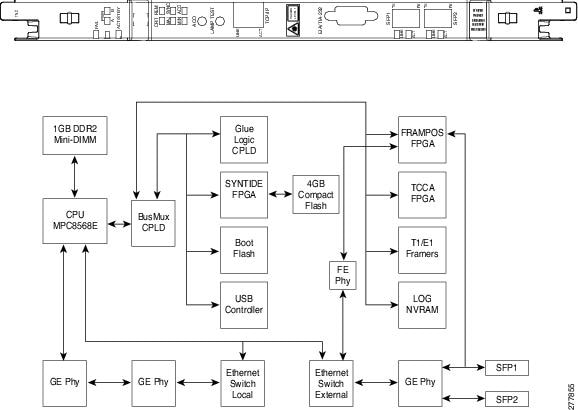
Figure 3-5 illustrates the faceplate and block diagram for the TNCE card.
Figure 3-5 TNCE Faceplate and Block Diagram
3.6.2 TNC and TNCE Card Functions
The functions of the TNC and TNCE cards are:
- Communication and Control for Controller Cards
- Optical Service Channel
- Timing Synchronization
- MultiShelf Management
- Database Storage
- Interface Ports
- External Alarms and Controls
- Lamp Test
- Redundant Controller Card Installation
- Card level indicators—Table G-1
- Network level indicators—Table G-13
- Power level indicators—Table G-12
- Port level indicators—Table G-14
- TNC and TNCE SFP indicators—Table G-15
- Protection Schemes
- Cards Supported by TNC/TNCE/TSC/TSCE
3.6.3 Related Procedures for TNC and TNCE Cards
The following is the list of procedures and tasks related to the configuration of the TNC and TNCE cards:
- G313 Install and Configure the TNC, TNCE, TSC, or TSCE Card
- NTP-G17 Set Up Computer for CTC
- DLP-G43 Disable or Bypass Proxy Service Using Internet Explorer (Windows)
- DLP-G44 Disable or Bypass Proxy Service Using Mozilla (Solaris)
- DLP-G48 Create Login Node Groups
- DLP-G49 Add a Node to the Current Session or Login Group
- DLP-G41 Set Up a Windows PC for Craft Connection to an ONS 15454 Using Automatic Host Detection
- NTP-G19 Set Up a CTC Computer for a Corporate LAN Connection to the ONS 15454
- G22 Verify Common Card Installation
- G250 Verify Digital Image Signing (DIS) Information
- NTP-G279 Monitor TNC and TNCE Card Performance
- G144 Provision a Multishelf Node
- G25 Set Battery Power Monitor Thresholds
- G26 Set Up CTC Network Access
- G143 Import the Cisco Transport Planner NE Update Configuration File
- G163 Upgrade Nodes in Single-Shelf Mode to Multishelf Mode
- G51 Verify DWDM Node Turn Up
- NTP-G81 Change CTC Network Access
- NTP-G146 Add a Rack, Passive Unit, or Shelf to a Multishelf Node
- NTP-G147 Delete a Passive Unit, Shelf, or Rack from a Multishelf Node
- G103 Back Up the Database
- G104 Restore the Database
- G106 Reset Cards Using CTC
- NTP-G277 Provision Alarms and Controls on the TNC, TNCE, TSC, or TSCE Card
- G105 Restore the Node to Factory Configuration
3.7 TSC and TSCE Cards
(Cisco ONS 15454 M2 and ONS 15454 M6 only)
The TSC and TSCE cards combine the functions of multiple cards such as TCC2P, ISC, and AIC-I cards. The card has a similar look and feel to TCC2/TCC2P/TCC3 cards.
Note![]() For TSC and TSCE cards specification, see the “TSC and TSCE Card Specifications (ONS 15454 M2 and ONS 15454 M6)” section in the Hardware Specifications document.
For TSC and TSCE cards specification, see the “TSC and TSCE Card Specifications (ONS 15454 M2 and ONS 15454 M6)” section in the Hardware Specifications document.
The TSC and TSCE cards are provisioned as master and slave in the ONS 15454 M6 shelf, and as a stand-alone card in the ONS 15454 M2 shelf. The TSC and TSCE cards serve as the processor card for the node.
On the ONS 15454 M6 shelf, install redundant TSC and TSCE cards in slots 1 and 8. If the active TSC or TSCE card fails, system traffic switches to the redundant TSC or TSCE card. The TSC and TSCE cards support line cards from slots 2 to 7.
On the ONS 15454 M2 shelf, install the stand-alone TSC and TSCE cards in slot 1. The TSC and TSCE cards support line cards in slots 2 and 3.
The TSC and TSCE cards monitor both the supply voltage inputs on the 15454-M6 shelf. The TSC and TSCE cards raise an alarm if one of the supply voltage inputs has a voltage out of the specified range. The 15454-M2 shelf has dual power supply.
You can insert and remove the TSC and TSCE cards even when the system is online, without impacting the system traffic.
The TSC and TSCE cards do not support optical service channel (OSC) and SFP ports.
You can upgrade the TSC or TSCE card to a TNC or TNCE card. During the upgrade, the TNC and TNCE cards do not support OSC functions such as UDC, VoIP, DCC, and timing function. However, you can still provision SFP ports on the TNC and TNCE cards during the upgrade. The TNC, TNCE, TSC, and TSCE cards cannot be inserted in the same shelf.
The TSC and TSCE cards support all the alarms supported by the TCC2P and AIC-I cards. The card adjusts the fan speed according to the temperature and reports a fan failure alarm.
Note![]() The LAN interface of the TSC and TSCE cards meet the standard Ethernet specifications by supporting a cable length of 328 ft (100 m) at temperatures from 32 to 149 degrees Fahrenheit (0 to 65 degrees Celsius). The interfaces can operate with a cable length of 32.8 ft (10 m) maximum at temperatures from -40 to 32 degrees Fahrenheit (-40 to 0 degrees Celsius).
The LAN interface of the TSC and TSCE cards meet the standard Ethernet specifications by supporting a cable length of 328 ft (100 m) at temperatures from 32 to 149 degrees Fahrenheit (0 to 65 degrees Celsius). The interfaces can operate with a cable length of 32.8 ft (10 m) maximum at temperatures from -40 to 32 degrees Fahrenheit (-40 to 0 degrees Celsius).
3.7.1 Faceplate and Block Diagram
The faceplate design of the TSC and TSCE cards allow sufficient space to insert or remove cables while accessing the Ethernet ports.
The TSC and TSCE cards can be installed only in slots 1 or 8 of the 15454-M6 shelf and in slot 1 of the 15454-M2 shelf. The TSC and TSCE cards have an identifier on the faceplate that matches with an identifier in the shelf. A key is also provided on the backplane interface connectors as identifier in the shelf.
The TSC and TSCE cards support field-programmable gate array (FPGA) for the backplane interface. The TSC cards have two FPGA: TCCA and SYNTIDE
The TSCE cards have one FPGA: VEGA
Figure 3-6 illustrates the faceplate and block diagram for the TSC card.
Figure 3-6 TSC Faceplate and Block Diagram
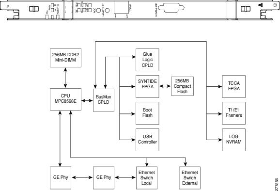
Figure 3-7 illustrates the faceplate for the TSCE card.

3.7.2 TSC and TSCE Card Functions
The functions of the TSC and TSCE cards are:
- Communication and Control for Controller Cards
- Timing Synchronization
- MultiShelf Management
- Database Storage
- Interface Ports
- External Alarms and Controls
- Lamp Test
- Redundant Controller Card Installation
- Card level indicators—Table G-1
- Network level indicators—Table G-13
- Power level indicators—Table G-12
- Port level indicators—Table G-14
- Protection Schemes
- Cards Supported by TNC/TNCE/TSC/TSCE
3.7.3 Related Procedures for TSC and TSCE Cards
The following is the list of procedures and tasks related to the configuration of the TSC and TSCE cards:
- G313 Install and Configure the TNC, TNCE, TSC, or TSCE Card
- NTP-G17 Set Up Computer for CTC
- DLP-G43 Disable or Bypass Proxy Service Using Internet Explorer (Windows)
- DLP-G44 Disable or Bypass Proxy Service Using Mozilla (Solaris)
- DLP-G48 Create Login Node Groups
- DLP-G49 Add a Node to the Current Session or Login Group
- DLP-G41 Set Up a Windows PC for Craft Connection to an ONS 15454 Using Automatic Host Detection
- NTP-G19 Set Up a CTC Computer for a Corporate LAN Connection to the ONS 15454
- G22 Verify Common Card Installation
- G250 Verify Digital Image Signing (DIS) Information
- G144 Provision a Multishelf Node
- G25 Set Battery Power Monitor Thresholds
- G26 Set Up CTC Network Access
- G143 Import the Cisco Transport Planner NE Update Configuration File
- G163 Upgrade Nodes in Single-Shelf Mode to Multishelf Mode
- G51 Verify DWDM Node Turn Up
- NTP-G81 Change CTC Network Access
- NTP-G146 Add a Rack, Passive Unit, or Shelf to a Multishelf Node
- NTP-G147 Delete a Passive Unit, Shelf, or Rack from a Multishelf Node
- G103 Back Up the Database
- G104 Restore the Database
- G106 Reset Cards Using CTC
- G103 Back Up the Database
- G104 Restore the Database
- G106 Reset Cards Using CTC
- NTP-G277 Provision Alarms and Controls on the TNC, TNCE, TSC, or TSCE Card
- G280 Modify Threshold Settings for the TNC and TNCE Cards
- NTP-G278 Upgrade the TSC Card to the TNC Card
- G105 Restore the Node to Factory Configuration
3.8 Digital Image Signing
(Cisco ONS 15454 M2 and ONS 15454 M6 only)
The DIS feature complies with the new U.S. Government Federal Information Processing Standard (FIPS) 140-3 to provide security for all software provided on the Cisco ONS 15454 M6 and ONS 15454 M2 platforms. This standard requires software to be digitally signed and verified for authenticity and integrity prior to load and execution.
DIS feature automatically provides increased protection. DIS focuses on software security and provides increased protection from attacks and threats to Cisco ONS 15454 M2 and ONS 15454 M6 products. DIS verifies software integrity and provides assurance that the software has not been tampered with or modified. Digitally signed Cisco software provides counterfeit protection.
New controller cards, such as TNC/TNCE/TSC/TSCE, provide services that authenticate the origin of the software running on the Cisco ONS 15454 M2 and Cisco ONS 15454 M6 platforms. The signage and verification process is transparent until verification fails.
3.8.1 DIS Identification
Digitally signed software can be identified by the last three characters appended to the working version and protected version field in CTC. The DIS conventions can be viewed under the working version displayed in the Maintenance > Software tab in CTC. For example, 9.2.0 (09.20-X10C-29.09-SDA) and 9.2.0 (09.20-010C-18.18-SPA).
The significance of the three characters appended to the software version is explained in Table:
3.8.2 Related Procedures for DIS
To verify DIS, see G250 Verify Digital Image Signing (DIS) Information.
3.9 AIC-I Card
Note![]() For hardware specifications, see the “AIC-I Card Specifications” section in the Hardware Specifications document.
For hardware specifications, see the “AIC-I Card Specifications” section in the Hardware Specifications document.
The optional Alarm Interface Controller–International (AIC-I) card provides customer-defined (environmental) alarms and controls and supports local and express orderwire. It provides 12 customer-defined input and 4 customer-defined input/output contacts. The physical connections are via the backplane wire-wrap pin terminals. If you use the additional alarm expansion panel (AEP), the AIC-I card can support up to 32 inputs and 16 outputs, which are connected on the AEP connectors. The AEP is compatible with ANSI shelves only. A power monitoring function monitors the supply voltage (–48 VDC).
3.9.1 Faceplate and Block Diagram
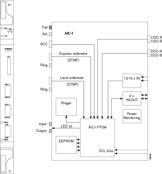
Figure 3-8 shows the AIC-I faceplate and a block diagram of the card.
Figure 3-8 AIC-I Faceplate and Block Diagram
3.9.2 AIC-I Card-Level Indicators
Table G-2 lists the card-level LEDs on the card.
3.9.3 External Alarms and Controls
The AIC-I card provides input/output alarm contact closures. You can define up to 12 external alarm inputs and 4 external alarm inputs/outputs (user configurable). The physical connections are made using the backplane wire-wrap pins or FMEC connections. For information about increasing the number of input/output contacts, see the “ONS 15454 ANSI Alarm Expansion Panel” section in the Cisco ONS 15454 Hardware Installation Guide .
LEDs on the front panel of the AIC-I indicate the status of the alarm lines, one LED representing all of the inputs and one LED representing all of the outputs. External alarms (input contacts) are typically used for external sensors such as open doors, temperature sensors, flood sensors, and other environmental conditions. External controls (output contacts) are typically used to drive visual or audible devices such as bells and lights, but they can control other devices such as generators, heaters, and fans.
You can program each of the twelve input alarm contacts separately. You can program each of the sixteen input alarm contacts separately. Choices include:
- Alarm on Closure or Alarm on Open
- Alarm severity of any level (Critical, Major, Minor, Not Alarmed, Not Reported)
- Service Affecting or Non-Service Affecting alarm-service level
- 63-character alarm description for CTC display in the alarm log
You cannot assign the fan-tray abbreviation for the alarm; the abbreviation reflects the generic name of the input contacts. The alarm condition remains raised until the external input stops driving the contact or you provision the alarm input.
The output contacts can be provisioned to close on a trigger or to close manually. The trigger can be a local alarm severity threshold, a remote alarm severity, or a virtual wire:
- Local NE alarm severity: A hierarchy of Not Reported, Not Alarmed, Minor, Major, or Critical alarm severities that you set to cause output closure. For example, if the trigger is set to Minor, a Minor alarm or above is the trigger.
- Remote NE alarm severity: Same as the local NE alarm severity but applies to remote alarms only.
- Virtual wire entities: You can provision any environmental alarm input to raise a signal on any virtual wire on external outputs 1 through 4 when the alarm input is an event. You can provision a signal on any virtual wire as a trigger for an external control output.
You can also program the output alarm contacts (external controls) separately. In addition to provisionable triggers, you can manually force each external output contact to open or close. Manual operation takes precedence over any provisioned triggers that might be present.
Note![]() For ANSI shelves, the number of inputs and outputs can be increased using the AEP. The AEP is connected to the shelf backplane and requires an external wire-wrap panel.
For ANSI shelves, the number of inputs and outputs can be increased using the AEP. The AEP is connected to the shelf backplane and requires an external wire-wrap panel.
3.9.4 Orderwire
Orderwire allows a crafts person to plug a phone set into an ONS 15454 and communicate with crafts people working at other ONS 15454s or other facility equipment. The orderwire is a pulse code modulation (PCM) encoded voice channel that uses E1 or E2 bytes in section/line overhead.
The AIC-I allows simultaneous use of both local (section overhead signal) and express (line overhead channel) orderwire channels on a SONET/SDH ring or particular optics facility. Express orderwire also allows communication via regeneration sites when the regenerator is not a Cisco device.
You can provision orderwire functions with CTC similar to the current provisioning model for DCC/GCC channels. In CTC, you provision the orderwire communications network during ring turn-up so that all NEs on the ring can reach one another. Orderwire terminations (that is, the optics facilities that receive and process the orderwire channels) are provisionable. Both express and local orderwire can be configured as on or off on a particular SONET/SDH facility. The ONS 15454 supports up to four orderwire channel terminations per shelf. This allows linear, single ring, dual ring, and small hub-and-spoke configurations. Orderwire is not protected in ring topologies such as bidirectional line switched ring (BLSR), multiplex section-shared protection ring (MS-SPRing), path protection, or subnetwork connection protection (SNCP) ring.

The ONS 15454 implementation of both local and express orderwire is broadcast in nature. The line acts as a party line. Anyone who picks up the orderwire channel can communicate with all other participants on the connected orderwire subnetwork. The local orderwire party line is separate from the express orderwire party line. Up to four OC-N/STM-N facilities for each local and express orderwire are provisionable as orderwire paths.
The AIC-I supports selective dual tone multi-frequency (DTMF) dialing for telephony connectivity, which causes one AIC-I card or all ONS 15454 AIC-I cards on the orderwire subnetwork to “ring.” The ringer/buzzer resides on the AIC-I. There is also a “ring” LED that mimics the AIC-I ringer. It flashes when a call is received on the orderwire subnetwork. A party line call is initiated by pressing *0000 on the DTMF pad. Individual dialing is initiated by pressing * and the individual four-digit number on the DTMF pad.
Table 3-3 shows the pins on the orderwire connector that correspond to the tip and ring orderwire assignments.
|
|
|
|---|---|
When provisioning the orderwire subnetwork, make sure that an orderwire loop does not exist. Loops cause oscillation and an unusable orderwire channel.
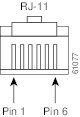
Figure 3-9 shows the standard RJ-11 connectors used for orderwire ports.
3.9.5 Power Monitoring
The AIC-I card provides a power monitoring circuit that monitors the supply voltage of –48 VDC for presence, under voltage, and over voltage.
3.9.6 User Data Channel
The user data channel (UDC) features a dedicated data channel of 64 kbps (F1 byte) between two nodes in an ONS 15454 network. Each AIC-I card provides two user data channels, UDC-A and UDC-B, through separate RJ-11 connectors on the front of the AIC-I card. Each UDC can be routed to an individual optical interface in the ONS 15454.
The UDC ports are standard RJ-11 receptacles. Table 3-4 lists the UDC pin assignments.
|
|
|
|---|---|
3.9.7 Data Communications Channel
The DCC features a dedicated data channel of 576 kbps (D4 to D12 bytes) between two nodes in an ONS 15454 network. Each AIC-I card provides two data communications channels, DCC-A and DCC-B, through separate RJ-45 connectors on the front of the AIC-I card. Each DCC can be routed to an individual optical interface in the ONS 15454.
The DCC ports are synchronous serial interfaces. The DCC ports are standard RJ-45 receptacles. Table 3-5 lists the DCC pin assignments.
|
|
|
|---|---|
3.9.8 Related Procedures for AIC-I Card
The following is the list of procedures and tasks related to the configuration of the AIC-I card:
3.10 MS-ISC-100T Card
Note![]() For hardware specifications, see the “MS-ISC-100T Card Specifications” section in the Hardware Specifications document.
For hardware specifications, see the “MS-ISC-100T Card Specifications” section in the Hardware Specifications document.
The Multishelf Internal Switch Card (MS-ISC-100T) is an Ethernet switch used to implement the multishelf LAN. It connects the node controller shelf to the network and to subtending shelves. The MS-ISC-100T must always be equipped on the node controller shelf; it cannot be provisioned on a subtending controller shelf.
The recommended configuration is to implement LAN redundancy using two MS-ISC-100T cards: one switch is connected to the Ethernet front panel port of the TCC2/TCC2P card in Slot 7, and the other switch is connected to the Ethernet front panel port of the TCC2/TCC2P card in Slot 11. The Ethernet configuration of the MS-ISC-100T card is part of the software package and is automatically loaded. The MS-ISC-100T card operates in Slots 1 to 6 and 12 to 17 on the node controller shelf; the recommended slots are Slot 6 and Slot 12.
Table 3-6 lists the MS-ISC-100T port assignments.
|
|
|
|---|---|
3.10.1 Faceplate Diagram
Figure 3-10 shows the card faceplate.
Figure 3-10 MS-ISC-100T Faceplate

3.10.2 MS-ISC-100T Card-Level Indicators
Table G-3 lists the card-level LEDs on the card.
3.10.3 Related Procedures for MS-ISC-100T Card
The following is the list of procedures and tasks related to the configuration of the MS-ISC-100T card:
3.11 Front Mount Electrical Connections
This section describes the MIC-A/P and MIC-C/T/P FMECs, which provide power, external alarm, and timing connections for the ONS 15454 ETSI shelf.
3.11.1 MIC-A/P FMEC
Note![]() For hardware specifications, see the “MIC-A/P FMEC Specifications (ETSI only)” section in the Hardware Specifications document.
For hardware specifications, see the “MIC-A/P FMEC Specifications (ETSI only)” section in the Hardware Specifications document.
The MIC-A/P FMEC provides connection for the BATTERY B input, one of the two possible redundant power supply inputs. It also provides connection for eight alarm outputs (coming from the TCC2/TCC2P card), sixteen alarm inputs, and four configurable alarm inputs/outputs. Its position is in Slot 23 i n the center of the subrack Electrical Facility Connection Assembly (EFCA) area.
The MIC-A/P FMEC has the following features:
- Connection for one of the two possible redundan t p ower supply inputs
- Connection for eight alarm outputs (coming from the TCC2/TCC2P card)
- Connection for four configurable alarm inputs/outputs
- Connection for sixteen alarm inputs
- Storage of manufacturing and inventory data
For proper system operation, both the MIC-A/P and MIC-C/T/P FMECs must be installed in the ONS 15454 ETSI shelf.
3.11.2 Faceplate and Block Diagram
MIC-A/P Faceplate shows the MIC-A/P faceplate.
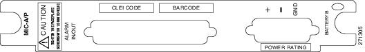
Figure 3-12 shows a block diagram of the MIC-A/P.
Figure 3-12 MIC-A/P Block Diagram
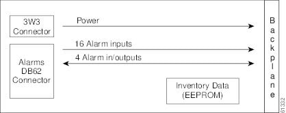
Table 3-7 shows the alarm interface pinouts on the MIC-A/P DB-62 connector.
|
|
|
|
|---|---|---|
3.11.3 MIC-C/T/P FMEC
Note![]() For hardware specifications, see the “MIC-C/T/P FMEC Specifications (ETSI only)” section in the Hardware Specifications document.
For hardware specifications, see the “MIC-C/T/P FMEC Specifications (ETSI only)” section in the Hardware Specifications document.
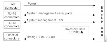
The MIC-C/T/P FMEC provides connection for the BATTERY A input, one of the two possible redundant power supply inputs. It also provides connection for system management serial port, system management LAN port, modem port (for future use), and system timing inputs and outputs. Install the MIC-C/T/P in Slot 24.
The MIC-C/T/P FMEC has the following features:
- Connection for one of the two possible redundan t p ower supply inputs
- Connection for two serial ports for local craft/modem (for future use)
- Connection for one LAN port
- Connection for two system timing inputs
- Connection for two system timing outputs
- Storage of manufacturing and inventory data
For proper system operation, both the MIC-A/P and MIC-C/T/P FMECs must be installed in the shelf.
3.11.4 Faceplate and Block Diagram
Figure 3-13 show s the MIC-C/T/P FMEC faceplate.
Figure 3-13 MIC-C/T/P Faceplate
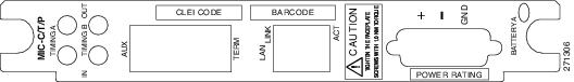
Figure 3-14 shows a block diagram of the MIC-C/T/P.
Figure 3-14 MIC-C/T/P Block Diagram
The MIC-C/T/P FMEC has one pair of LEDs located on the RJ45 LAN connector. The green LED is on when a link is present, and the amber LED is on when data is being transferred.
3.12 Procedures for Control Cards
The procedures described below explain how to install the control cards needed for the Cisco ONS 15454, Cisco ONS 15454 M2, and Cisco ONS 15454 M6 platforms.
3.12.1 Before You Begin
Before performing any of the following procedures, investigate all alarms and clear any trouble conditions. Refer to the Cisco ONS 15454 DWDM Troubleshooting Guide as necessary.
This section lists the chapter procedures (NTPs). Turn to a procedure for applicable tasks (DLPs).
- G15 Install the Common Control Cards—Complete this procedure to install the control cards needed for the ONS 15454 platform.
- G313 Install and Configure the TNC, TNCE, TSC, or TSCE Card—Complete this procedure to install the control cards needed for the ONS 15454 M2 and ONS 15454 M6 platforms.
NTP-G15 Install the Common Control Cards
This procedure describes how to install the control cards needed for the ONS 15454 platform. |
|
Redundant TCC2/TCC2P/TCC3 cards on ONS 15454 shelf (required) |
|
Following procedures in the Cisco ONS 15454 Hardware Installation Guide: |
|

Warning![]() During this procedure, wear grounding wrist straps to avoid ESD damage to the card. Do not directly touch the backplane with your hand or any metal tool, or you could shock yourself. Statement 94
During this procedure, wear grounding wrist straps to avoid ESD damage to the card. Do not directly touch the backplane with your hand or any metal tool, or you could shock yourself. Statement 94
Note![]() If protective clips are installed on the backplane connectors of the cards, remove the clips before installing the cards.
If protective clips are installed on the backplane connectors of the cards, remove the clips before installing the cards.
Note![]() If you install a card incorrectly, the FAIL LED flashes continuously.
If you install a card incorrectly, the FAIL LED flashes continuously.
Step 1![]() (ONS 15454 only) Complete the G33 Install the TCC2, TCC2P, or TCC3 Card.
(ONS 15454 only) Complete the G33 Install the TCC2, TCC2P, or TCC3 Card.
Note![]() If you install the wrong card in a slot, see the NTP-G107 Remove Permanently or Remove and Replace DWDM Cards.
If you install the wrong card in a slot, see the NTP-G107 Remove Permanently or Remove and Replace DWDM Cards.
Step 2![]() (ONS 15454 only) Complete the G34 Install the AIC-I Card, if necessary.
(ONS 15454 only) Complete the G34 Install the AIC-I Card, if necessary.
Step 3![]() (ONS 15454 only) Complete the G309 Install the MS-ISC-100T Card, if necessary.
(ONS 15454 only) Complete the G309 Install the MS-ISC-100T Card, if necessary.
Stop. You have completed this procedure.
DLP-G33 Install the TCC2, TCC2P, or TCC3 Card
Note![]() Allow each card to boot completely before installing the next card.
Allow each card to boot completely before installing the next card.
Step 1![]() Open the latches/ejectors of the first TCC2/TCC2P/TCC3 card that you will install.
Open the latches/ejectors of the first TCC2/TCC2P/TCC3 card that you will install.
Step 2![]() Use the latches/ejectors to firmly slide the card along the guide rails until the card plugs into the receptacle at the back of the slot (Slot 7 or 11).
Use the latches/ejectors to firmly slide the card along the guide rails until the card plugs into the receptacle at the back of the slot (Slot 7 or 11).
Note![]() In Step 4, you will be instructed to watch the LED activity (sequence) on the front of the TCC2/TCC2P/TCC3 card. This activity begins immediately after you close the latches in Step 3.
In Step 4, you will be instructed to watch the LED activity (sequence) on the front of the TCC2/TCC2P/TCC3 card. This activity begins immediately after you close the latches in Step 3.
Step 3![]() Verify that the card is inserted correctly and close the latches/ejectors on the card.
Verify that the card is inserted correctly and close the latches/ejectors on the card.
Note![]() It is possible to close the latches/ejectors when the card is not completely plugged into the back panel of the shelf. Ensure that you cannot insert the card any farther.
It is possible to close the latches/ejectors when the card is not completely plugged into the back panel of the shelf. Ensure that you cannot insert the card any farther.
If you insert a card into a slot provisioned for a different card, all LEDs turn off.
Step 4![]() As needed, go to Step a to verify the LED activity on the TCC2 card. For the TCC2P go to Step
As needed, go to Step a to verify the LED activity on the TCC2 card. For the TCC2P go to Step ![]() b . For the TCC3 card go to Step
b . For the TCC3 card go to Step ![]() c .
c .
- All LEDs turn on briefly. The red FAIL LED and the yellow ACT/STBY LED turn on for about 15 seconds. (For TCC3 card it takes around 20 to 25 seconds)
- The red FAIL LED and the green ACT/STBY LED turn on for about 40 seconds.
- The red FAIL LED blinks for about 15 seconds.
- The red FAIL LED turns on for about 15 seconds. All LEDs turn on for about 3 seconds before turning off for about 3 seconds.
- Both green PWR LEDs turn on for 10 seconds. The PWR LEDs then turn red for 2 to 3 minutes before going to steady green.
- While the PWR LEDs are red for two to three minutes, the ACT/STBY turn on.
- The boot-up process is complete when the PWR LEDs turn green and the ACT/STBY remains on. (The ACT/STBY LED will be green if this is the first TCC2 card installed, and amber if this is the second TCC2 card installed.)
Note![]() It might take up to four minutes for the A and B power alarms to clear.
It might take up to four minutes for the A and B power alarms to clear.
Note![]() Alarm LEDs might be on; disregard alarm LEDs until you are logged into CTC and can view the Alarms tab.
Alarm LEDs might be on; disregard alarm LEDs until you are logged into CTC and can view the Alarms tab.
Note![]() If you are logged into CTC, the SFTWDOWN alarm might appear as many as two times while the TCC2 card initializes. The alarm should clear after the card completely boots.
If you are logged into CTC, the SFTWDOWN alarm might appear as many as two times while the TCC2 card initializes. The alarm should clear after the card completely boots.
Note![]() If the FAIL LED is on continuously, see the tip in Step 8 about the TCC2 card automatic upload.
If the FAIL LED is on continuously, see the tip in Step 8 about the TCC2 card automatic upload.
- All LEDs turn on briefly. The red FAIL LED, the yellow ACT/STBY LED, the green SYNC LED, and the green ACO LED turn on for about 15 seconds.
- The red FAIL LED and the green ACT/STBY LED turn on for about 30 seconds.
- The red FAIL LED blinks for about 3 seconds.
- The red FAIL LED turns on for about 15 seconds.
- The red FAIL LED blinks for about 10 seconds and then becomes solid.
- All LEDs (including the CRIT, MAJ, MIN, REM, SYNC, and ACO LEDs) blink once and turn off for about 5 seconds.
- Both green PWR LEDs turn on for 10 seconds. The PWR LEDs then turn red for 2 to 3 minutes before going to steady green. During this time, the ACT/STBY, MJ, and MN LEDs might turn on, followed by the SNYC LED briefly.
- The boot-up process is complete when the PWR LEDs turn green and the yellow ACT/STBY remains on. (The ACT/STBY LED will be green if this is the first TCC2P card installed, and yellow if this is the second TCC2P card installed.)
Note![]() It might take up to three minutes for the A and B power alarms to clear.
It might take up to three minutes for the A and B power alarms to clear.
Note![]() Alarm LEDs might be on; disregard alarm LEDs until you are logged into CTC and can view the Alarms tab.
Alarm LEDs might be on; disregard alarm LEDs until you are logged into CTC and can view the Alarms tab.
Note![]() If you are logged into CTC, the SFTWDOWN alarm might appear as many as two times while the TCC2P card initializes. The alarm should clear after the card completely boots.
If you are logged into CTC, the SFTWDOWN alarm might appear as many as two times while the TCC2P card initializes. The alarm should clear after the card completely boots.
Note![]() If the FAIL LED is on continuously, see the tip in Step 8 about the TCC2P card automatic upload.
If the FAIL LED is on continuously, see the tip in Step 8 about the TCC2P card automatic upload.
- All LEDs turn on briefly. The red FAIL LED, the yellow ACT/STBY LED, the green SYNC LED, and the green ACO LED turn on for about 25 seconds.
- The red FAIL LED and the green ACT/STBY LED turn on for about 15 seconds.
- The red FAIL LED blinks for about 3 seconds.
- The red FAIL LED turns on for about 60 seconds.
- The red FAIL LED blinks for about 15 seconds and then becomes solid (the LED is turned on for about 20 seconds).
- All LEDs (including the CRIT, MAJ, MIN, REM, SYNC, and ACO LEDs) blink once and turn off for about 5 seconds.
- Both green PWR LEDs turn on for 10 seconds. The PWR LEDs then turn red for 2 to 3 minutes before going to steady green. During this time, the ACT/STBY, MJ, and MN LEDs might turn on, followed by the SNYC LED briefly.
- The boot-up process is complete when the PWR LEDs turn green and the yellow ACT/STBY remains on. (The ACT/STBY LED will be green if this is the first TCC3 card installed, and yellow if this is the second TCC3 card installed.)
Note![]() It might take up to three minutes for the A and B power alarms to clear.
It might take up to three minutes for the A and B power alarms to clear.
Note![]() Alarm LEDs might be on; disregard alarm LEDs until you are logged into CTC and can view the Alarms tab.
Alarm LEDs might be on; disregard alarm LEDs until you are logged into CTC and can view the Alarms tab.
Note![]() If you are logged into CTC, the SFTWDOWN alarm might appear as many as two times while the TCC3 card initializes. The alarm should clear after the card completely boots.
If you are logged into CTC, the SFTWDOWN alarm might appear as many as two times while the TCC3 card initializes. The alarm should clear after the card completely boots.
Note![]() If the FAIL LED is on continuously, see the tip in Step 8 about the TCC3 card automatic upload.
If the FAIL LED is on continuously, see the tip in Step 8 about the TCC3 card automatic upload.
Step 5![]() Verify that the ACT/STBY LED is green if this is the first powered-up TCC2/TCC2P/TCC3 card installed, or yellow for standby if this is the second powered-up TCC2/TCC2P/TCC3. The IP address, temperature of the node, and time of day appear on the LCD. The default time and date is 12:00 AM, January 1, 1970.
Verify that the ACT/STBY LED is green if this is the first powered-up TCC2/TCC2P/TCC3 card installed, or yellow for standby if this is the second powered-up TCC2/TCC2P/TCC3. The IP address, temperature of the node, and time of day appear on the LCD. The default time and date is 12:00 AM, January 1, 1970.
Step 6![]() The LCD cycles through the IP address (the default is 192.1.0.2), node name, and software version. Verify that the correct software version is shown on the LCD. The software text string indicates the node type (SDH or SONET) and software release. (For example: SDH 09.20-05L-20.10 indicates it is an SDH software load, Release 9.2. The numbers following the release number do not have any significance.)
The LCD cycles through the IP address (the default is 192.1.0.2), node name, and software version. Verify that the correct software version is shown on the LCD. The software text string indicates the node type (SDH or SONET) and software release. (For example: SDH 09.20-05L-20.10 indicates it is an SDH software load, Release 9.2. The numbers following the release number do not have any significance.)
Step 7![]() If the LCD shows the correct software version, continue with Step 8. If the LCD does not show the correct software version, refer to your next level of technical support, upgrade the software, or remove the TCC2/TCC2P/TCC3 card and install a replacement card.
If the LCD shows the correct software version, continue with Step 8. If the LCD does not show the correct software version, refer to your next level of technical support, upgrade the software, or remove the TCC2/TCC2P/TCC3 card and install a replacement card.
Refer to the release-specific software upgrade document to replace the software. To replace the TCC2/TCC2P/TCC3 card, refer to the Cisco ONS 15454 DWDM Troubleshooting Guide.
Step 8![]() Repeat Steps 1 through 7 for the redundant TCC2/TCC2P/TCC3 card. If both TCC2/TCC2P/TCC3 cards are already installed, proceed to Step
Repeat Steps 1 through 7 for the redundant TCC2/TCC2P/TCC3 card. If both TCC2/TCC2P/TCC3 cards are already installed, proceed to Step ![]() 9 .
9 .

Tip If you install a standby TCC2/TCC2P/TCC3 card that has a different software version than the active TCC2/TCC2P/TCC3 card, the newly installed standby TCC2/TCC2P/TCC3 card automatically copies the software version from the active TCC2/TCC2P/TCC3 card. You do not need to do anything in this situation. However, the loading TCC2/TCC2P/TCC3 card does not boot up in the normal manner. When the standby card is first inserted, the LEDs follow most of the normal boot-up sequence. However, after the red FAIL LED turns on for about 5 seconds, the FAIL LED and the ACT/STBY LED begin to flash alternately for up to 30 minutes while the new software loads onto the active TCC2/TCC2P/TCC3 card. After loading the new software, the upgraded TCC2/TCC2P/TCC3 card’s LEDs repeat the appropriate bootup sequence, and the amber ACT/STBY LED turns on.
Note![]() If you insert a card into a slot provisioned for a different card, all LEDs turn off.
If you insert a card into a slot provisioned for a different card, all LEDs turn off.
Note![]() Alarm LEDs might be on; disregard alarm LEDs until you are logged into CTC and can view the Alarms tab.
Alarm LEDs might be on; disregard alarm LEDs until you are logged into CTC and can view the Alarms tab.
Step 9![]() Return to your originating procedure (NTP).
Return to your originating procedure (NTP).
DLP-G34 Install the AIC-I Card
This task installs the AIC-I card. The AIC-I card provides connections for external alarms and controls (environmental alarms). |
|
Note![]() When installing cards, allow each card to boot completely before installing the next card.
When installing cards, allow each card to boot completely before installing the next card.
Step 1![]() Open the latches/ejectors on the card.
Open the latches/ejectors on the card.
Step 2![]() Use the latches/ejectors to firmly slide the card along the guide rails in Slot 9 until the card plugs into the receptacle at the back of the slot.
Use the latches/ejectors to firmly slide the card along the guide rails in Slot 9 until the card plugs into the receptacle at the back of the slot.
Step 3![]() Verify that the card is inserted correctly and close the latches/ejectors on the card.
Verify that the card is inserted correctly and close the latches/ejectors on the card.
Note![]() It is possible to close the latches/ejectors when the card is not completely plugged into the backplane. Ensure that you cannot insert the card any further.
It is possible to close the latches/ejectors when the card is not completely plugged into the backplane. Ensure that you cannot insert the card any further.
Note![]() If the red FAIL LED does not turn on, check the power.
If the red FAIL LED does not turn on, check the power.
Note![]() It might take up to 3 minutes for the PWR A and PWR B LEDs to update.
It might take up to 3 minutes for the PWR A and PWR B LEDs to update.
Note![]() If you insert a card into a slot provisioned for a different card, no LEDs turn on.
If you insert a card into a slot provisioned for a different card, no LEDs turn on.
Note![]() If the red FAIL LED is on continuously or the LEDs act erratically, the card is not installed properly. Remove the card and repeat Steps 1 to 4.
If the red FAIL LED is on continuously or the LEDs act erratically, the card is not installed properly. Remove the card and repeat Steps 1 to 4.
Step 5![]() Return to your originating procedure (NTP).
Return to your originating procedure (NTP).
DLP-G309 Install the MS-ISC-100T Card
Note![]() When installing cards, allow each card to boot completely before installing the next card.
When installing cards, allow each card to boot completely before installing the next card.
Note![]() The MS-ISC-100T is not supported in a subtended shelf.
The MS-ISC-100T is not supported in a subtended shelf.
Step 1![]() Open the latches/ejectors on the card.
Open the latches/ejectors on the card.
Step 2![]() Use the latches/ejectors to firmly slide the card along the guide rails into the appropriate slot in the node controller shelf until the card plugs into the receptacle at the back of the slot. The card can be installed in any slot from Slot 1 to 6 or 12 to 17. Cisco recommends that you install the MS-ISC-100T cards in Slot 6 and Slot 12.
Use the latches/ejectors to firmly slide the card along the guide rails into the appropriate slot in the node controller shelf until the card plugs into the receptacle at the back of the slot. The card can be installed in any slot from Slot 1 to 6 or 12 to 17. Cisco recommends that you install the MS-ISC-100T cards in Slot 6 and Slot 12.
Step 3![]() Verify that the card is inserted correctly and close the latches/ejectors on the card.
Verify that the card is inserted correctly and close the latches/ejectors on the card.
Note![]() It is possible to close the latches/ejectors when the card is not completely plugged into the backplane. Ensure that you cannot insert the card any further.
It is possible to close the latches/ejectors when the card is not completely plugged into the backplane. Ensure that you cannot insert the card any further.
Step 4![]() Verify the LED activity:
Verify the LED activity:
- The red FAIL LED blinks for 35 to 45 seconds.
- The red FAIL LED turns on for 15 to 20 seconds.
- The red FAIL LED blinks for approximately 3 minutes.
- The red FAIL LED turns on for approximately 6 minutes.
- The green ACT or ACT/STBY LED turns on. The SF LED can persist until all card ports connect to their far end counterparts and a signal is present.
Note![]() If the red FAIL LED does not turn on, check the power.
If the red FAIL LED does not turn on, check the power.
Note![]() If you insert a card into a slot provisioned for a different card, all LEDs turn off.
If you insert a card into a slot provisioned for a different card, all LEDs turn off.
Step 5![]() Repeat Steps 1 through 4 for the redundant MS-ISC-100T card.
Repeat Steps 1 through 4 for the redundant MS-ISC-100T card.
Step 6![]() Return to your originating procedure (NTP).
Return to your originating procedure (NTP).
NTP-G313 Install and Configure the TNC, TNCE, TSC, or TSCE Card
This procedure describes how to install and configure the TNC, TNCE, TSC, or TSCE card. TNC, TNCE, TSC, and TSCE cards are the control cards needed for the ONS 15454 M2 and ONS 15454 M6 platforms. |
|
Redundant TNC/TNCE/TSC/TSCE cards on ONS 15454 M6 shelf (required) Stand-alone TNC/TNCE/TSC/TSCE card on ONS 15454 M2 shelf (required) |
|
Following procedures in the Cisco ONS 15454 Hardware Installation Guide: |
|
Warning![]() During this procedure, wear grounding wrist straps to avoid ESD damage to the card. Do not directly touch the backplane with your hand or any metal tool, or you could shock yourself. Statement 94
During this procedure, wear grounding wrist straps to avoid ESD damage to the card. Do not directly touch the backplane with your hand or any metal tool, or you could shock yourself. Statement 94
Note![]() If you install a card incorrectly, the FAIL LED flashes continuously.
If you install a card incorrectly, the FAIL LED flashes continuously.
Step 1![]() Complete the G604 Install the TNC, TNCE, TSC, or TSCE Card.
Complete the G604 Install the TNC, TNCE, TSC, or TSCE Card.
Note![]() If you install the wrong card in a slot, see the NTP-G107 Remove Permanently or Remove and Replace DWDM Cards.
If you install the wrong card in a slot, see the NTP-G107 Remove Permanently or Remove and Replace DWDM Cards.
Step 2![]() Complete the G605 Provision PPM and Port for the TNC and TNCE Cards.
Complete the G605 Provision PPM and Port for the TNC and TNCE Cards.
Step 3![]() Complete the G606 Configure UDC and VoIP for the TNC and TNCE Cards.
Complete the G606 Configure UDC and VoIP for the TNC and TNCE Cards.
Step 4![]() Complete the G774 Change the Frame Type on the OSC.
Complete the G774 Change the Frame Type on the OSC.
Stop. You have completed this procedure.
DLP-G604 Install the TNC, TNCE, TSC, or TSCE Card
Note![]() The ONS 15454 M2 shelf supports stand-alone control cards such as TNC, TSC, TNCE, or TSCE. During replacement or removal of the control card, ensure that the optical fibers are not disturbed. The fibers must be correctly routed in the retention feature mounted on the front side of the shelf.
The ONS 15454 M2 shelf supports stand-alone control cards such as TNC, TSC, TNCE, or TSCE. During replacement or removal of the control card, ensure that the optical fibers are not disturbed. The fibers must be correctly routed in the retention feature mounted on the front side of the shelf.
Note![]() Allow each TNC/TNCE/TSC/TSCE card to boot completely before installing the redundant TNC/TNCE/TSC/TSCE card.
Allow each TNC/TNCE/TSC/TSCE card to boot completely before installing the redundant TNC/TNCE/TSC/TSCE card.
Note![]() On the ONS 15454 M6 shelf, install the TNC/TNCE/TSC/TSCE cards in slots 1 and 8 for redundancy. On the ONS 15454 M2 shelf, install the stand-alone TNC/TNCE/TSC/TSCE card in slot 1. For more information, see the “Card Slot Requirements” section in the Cisco ONS 15454 Hardware Installation Guide.
On the ONS 15454 M6 shelf, install the TNC/TNCE/TSC/TSCE cards in slots 1 and 8 for redundancy. On the ONS 15454 M2 shelf, install the stand-alone TNC/TNCE/TSC/TSCE card in slot 1. For more information, see the “Card Slot Requirements” section in the Cisco ONS 15454 Hardware Installation Guide.
Note![]() You cannot insert the TNC/TNCE/TSC/TSCE cards in other slots due to mechanical constraints. To identify the card slot, match the symbol placed on the lower side of the card front panel with the symbol in the shelf.
You cannot insert the TNC/TNCE/TSC/TSCE cards in other slots due to mechanical constraints. To identify the card slot, match the symbol placed on the lower side of the card front panel with the symbol in the shelf.
Step 1![]() Open the latches/ejectors of the first TNC/TNCE/TSC/TSCE card that you will install.
Open the latches/ejectors of the first TNC/TNCE/TSC/TSCE card that you will install.
Step 2![]() Use the latches/ejectors to firmly slide the card horizontally along the guide rails until the card plugs into the receptacle at the back of the slot (slot 1 or 8 in the ONS 15454 M6 shelf and slot 1 in the ONS 15454 M2 shelf).
Use the latches/ejectors to firmly slide the card horizontally along the guide rails until the card plugs into the receptacle at the back of the slot (slot 1 or 8 in the ONS 15454 M6 shelf and slot 1 in the ONS 15454 M2 shelf).
Step 3![]() Verify that the card is inserted correctly, and close the latches/ejectors on the card.
Verify that the card is inserted correctly, and close the latches/ejectors on the card.
If you insert a card into a slot assigned for a different card, all LEDs turn off.
Step 4![]() As needed, verify the LED activity on the TNC/TNCE/TSC/TSCE card.
As needed, verify the LED activity on the TNC/TNCE/TSC/TSCE card.
- The red FAIL LED, PWR LED turn on briefly.
- The red FAIL LED turns on for about 10 seconds.
- The red FAIL LED and the amber ACT/STBY LED turn on for about 30 seconds.
- The red FAIL LED blinks for about 10 seconds.
- The red FAIL LED turns on for about 15 seconds.
- All the LEDs including the CRIT, MAJ, MIN, REM, SYNC, and ACO LEDs blink once and turn off for about 10 seconds.
- ACT/STBY LED blinks for about 1 second.
- All the LEDs including the CRIT, MAJ, MIN, REM, SYNC, and ACO LEDs turn off for about 10 seconds.
- The ACT/STBY, ACO, and PWR LEDs turn on.
- The boot-up process is complete when the PWR LEDs turn green and the amber ACT/STBY remains on. The ACT/STBY LED turns green if this is the first TNC/TNCE/TSC/TSCE card installed, and amber if this is the second TNC/TNCE/TSC/TSCE card installed.
Note![]() It might take up to four minutes for the power alarms to clear.
It might take up to four minutes for the power alarms to clear.
Note![]() Alarm LEDs might be on. After completing the TNC/TNCE/TSC/TSCE card installation, log in to CTC and click the Alarms tab to display the alarms raised on the card. For procedure to clear the alarm, see the Cisco ONS DWDM Troubleshooting Guide.
Alarm LEDs might be on. After completing the TNC/TNCE/TSC/TSCE card installation, log in to CTC and click the Alarms tab to display the alarms raised on the card. For procedure to clear the alarm, see the Cisco ONS DWDM Troubleshooting Guide.
Note![]() During the TNC/TNCE/TSC/TSCE card initialization, the SFTWDOWN alarm appears twice. The alarm clears after the TNC/TNCE/TSC/TSCE card boots completely.
During the TNC/TNCE/TSC/TSCE card initialization, the SFTWDOWN alarm appears twice. The alarm clears after the TNC/TNCE/TSC/TSCE card boots completely.
Note![]() If the FAIL LED is on continuously, see the tip in Step 8 about the TNC/TNCE/TSC/TSCE card automatic upload.
If the FAIL LED is on continuously, see the tip in Step 8 about the TNC/TNCE/TSC/TSCE card automatic upload.
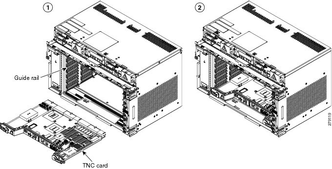
Figure 3-15 illustrates the installation of TNC and TNCE cards on ONS 15454 M6 shelf.
Figure 3-15 Installing TNC and TNCE Cards on ONS 15454 M6 Shelf
Step 5![]() Verify that the ACT/STBY LED is green if this is the first powered-up TNC/TNCE/TSC/TSCE card installed or amber if this is the second powered-up TNC/TNCE/TSC/TSCE. The IP address, temperature of the node, and time of day appear on the LCD. The default time and date is 12:00 AM, January 1, 1970.
Verify that the ACT/STBY LED is green if this is the first powered-up TNC/TNCE/TSC/TSCE card installed or amber if this is the second powered-up TNC/TNCE/TSC/TSCE. The IP address, temperature of the node, and time of day appear on the LCD. The default time and date is 12:00 AM, January 1, 1970.
Step 6![]() The LCD cycles through the IP address (the default is 192.1.0.2), node name, and software version. Verify that the correct software version is shown on the LCD. The software text string indicates the node type (SDH or SONET) and software release. (For example: SDH 09.20-05L-20.10 indicates it is an SDH software load, Release 9.2. The numbers following the release number do not have any significance.)
The LCD cycles through the IP address (the default is 192.1.0.2), node name, and software version. Verify that the correct software version is shown on the LCD. The software text string indicates the node type (SDH or SONET) and software release. (For example: SDH 09.20-05L-20.10 indicates it is an SDH software load, Release 9.2. The numbers following the release number do not have any significance.)
Step 7![]() If the LCD shows the correct software version, continue with Step 8. If the LCD does not show the correct software version, refer to your next level of technical support, upgrade the software, or remove the TNC/TNCE/TSC/TSCE card and install a replacement card. Refer to the release-specific software upgrade document to replace the software.
If the LCD shows the correct software version, continue with Step 8. If the LCD does not show the correct software version, refer to your next level of technical support, upgrade the software, or remove the TNC/TNCE/TSC/TSCE card and install a replacement card. Refer to the release-specific software upgrade document to replace the software.
Step 8![]() (ONS 15454 M6 shelf only) Repeat Steps 1 through 7 for the redundant TNC/TNCE/TSC/TSCE card.
(ONS 15454 M6 shelf only) Repeat Steps 1 through 7 for the redundant TNC/TNCE/TSC/TSCE card.
Tip If you install a standby TNC/TNCE/TSC/TSCE card that has a different software version than the active TNC/TNCE/TSC/TSCE card, the standby TNC/TNCE/TSC/TSCE card copies the software version from the active TNC/TNCE/TSC/TSCE card. When the standby card is first inserted, the LEDs follow the normal boot-up sequence. However, after the red FAIL LED turns on for about 5 seconds, the FAIL LED and the ACT/STBY LED begin to flash alternately for up to 30 minutes. After loading the new software, the upgraded TNC/TNCE/TSC/TSCE cards LEDs repeat the appropriate bootup sequence, and the amber ACT/STBY LED turns on.
Step 9![]() Return to your originating procedure (NTP).
Return to your originating procedure (NTP).
DLP-G605 Provision PPM and Port for the TNC and TNCE Cards
(ONS 15454 M2 and ONS 15454 M6 only) This task provisions a PPM and port on TNC and TNCE cards. PPMs are created to support the OSC function. |
|
Step 1![]() In node view (single-shelf mode) or shelf view (multishelf view), double-click the TNC and TNCE cards where you want to provision PPM and port settings.
In node view (single-shelf mode) or shelf view (multishelf view), double-click the TNC and TNCE cards where you want to provision PPM and port settings.
Step 2![]() Click the Provisioning > Pluggable Port Modules tabs.
Click the Provisioning > Pluggable Port Modules tabs.
Step 3![]() In the Pluggable Port Modules area, click Create. The Create PPM dialog box appears.
In the Pluggable Port Modules area, click Create. The Create PPM dialog box appears.
Step 4![]() In the Create PPM dialog box, complete the following:
In the Create PPM dialog box, complete the following:
Step 5![]() Click OK. The newly created PPM appears in the Pluggable Port Modules area. The row in the Pluggable Port Modules area becomes white when the PPM is inserted and the Actual Equipment Type column lists the name of PPM.
Click OK. The newly created PPM appears in the Pluggable Port Modules area. The row in the Pluggable Port Modules area becomes white when the PPM is inserted and the Actual Equipment Type column lists the name of PPM.
Step 6![]() In the Pluggable Ports area, click Create. The Create Port dialog box appears.
In the Pluggable Ports area, click Create. The Create Port dialog box appears.
Step 7![]() In the Create Ports dialog box, complete the following:
In the Create Ports dialog box, complete the following:
Note![]() OC-3 can be configured only on PPM port 1. FE and ONE-GE can be configured on both the ports. If the port type is FE, then disable ALS before provisioning OSC on that port.
OC-3 can be configured only on PPM port 1. FE and ONE-GE can be configured on both the ports. If the port type is FE, then disable ALS before provisioning OSC on that port.
Step 8![]() Click OK. The newly created port appears in the Pluggable Ports area. The port type you provisioned is listed
Click OK. The newly created port appears in the Pluggable Ports area. The port type you provisioned is listed![]() in the Rate column.
in the Rate column.
Step 9![]() Repeat Steps 3 through 8 to provision another PPM and port on the TNC and TNCE cards.
Repeat Steps 3 through 8 to provision another PPM and port on the TNC and TNCE cards.
Step 10![]() Return to your originating procedure (NTP).
Return to your originating procedure (NTP).
DLP-G606 Configure UDC and VoIP for the TNC and TNCE Cards
(ONS 15454 M2 and ONS 15454 M6 only) This task configures UDC and VoIP traffic for the TNC and TNCE cards. |
|
Note![]() Each TNC and TNCE cards support UDC/VoIP configuration. You can configure UDC or VoIP on the two SFP ports present on the TNC and TNCE cards. The TNC and TNCE cards support the UDC/VoIP configuration only when OSC is provisioned on the SFP ports.
Each TNC and TNCE cards support UDC/VoIP configuration. You can configure UDC or VoIP on the two SFP ports present on the TNC and TNCE cards. The TNC and TNCE cards support the UDC/VoIP configuration only when OSC is provisioned on the SFP ports.
Note![]() If two nodes are connected through the fiber and if the TNC and TNCE cards in one node has UDC configuration, the TNC and TNCE cards in the other node must also have UDC configuration. The same rule applies to VoIP configuration.
If two nodes are connected through the fiber and if the TNC and TNCE cards in one node has UDC configuration, the TNC and TNCE cards in the other node must also have UDC configuration. The same rule applies to VoIP configuration.
Step 1![]() In node view (single-shelf mode) or shelf view (multishelf view), double-click the TNC and TNCE cards where you want to configure UDC and VoIP.
In node view (single-shelf mode) or shelf view (multishelf view), double-click the TNC and TNCE cards where you want to configure UDC and VoIP.
Step 2![]() Click the Provisioning > UDC / VOIP tabs.
Click the Provisioning > UDC / VOIP tabs.
Step 3![]() From the Service Type drop-drop list, choose UDC or VOIP.
From the Service Type drop-drop list, choose UDC or VOIP.
Note![]() You can configure UDC or VoIP on only one SFP port at a time per TNC or TNCE card. If you want to configure UDC or VoIP on the second SFP port, choose NONE from the Service Type drop-down list for the first port and then choose UDC or VoIP for the second port.
You can configure UDC or VoIP on only one SFP port at a time per TNC or TNCE card. If you want to configure UDC or VoIP on the second SFP port, choose NONE from the Service Type drop-down list for the first port and then choose UDC or VoIP for the second port.
Step 5![]() Return to your originating procedure (NTP).
Return to your originating procedure (NTP).
DLP-G774 Change the Frame Type on the OSC
Step 1![]() Delete the OC-3, STM1, FE, or ONE_GE OSC communication channel. See DLP-G186 Delete an OSC Termination.
Delete the OC-3, STM1, FE, or ONE_GE OSC communication channel. See DLP-G186 Delete an OSC Termination.
Step 2![]() Click the Provisioning > WDM-ANS > Internal Patchcords tabs.
Click the Provisioning > WDM-ANS > Internal Patchcords tabs.
Step 3![]() Choose the internal patchcord that is associated with OSC and click Delete.
Choose the internal patchcord that is associated with OSC and click Delete.
Step 4![]() Delete the OSC payload on the TNC/TNCE card.
Delete the OSC payload on the TNC/TNCE card.
a.![]() In node view (single-shelf mode) or shelf view (multishelf view), double-click the TNC/TNCE card where you want to delete the OSC payload.
In node view (single-shelf mode) or shelf view (multishelf view), double-click the TNC/TNCE card where you want to delete the OSC payload.
b.![]() Click the Provisioning > Pluggable Port Modules tabs.
Click the Provisioning > Pluggable Port Modules tabs.
c.![]() In the Pluggable Ports area, choose the OSC payload that you want to delete and click Delete.
In the Pluggable Ports area, choose the OSC payload that you want to delete and click Delete.
Step 5![]() Provision the OSC payload on the TNC/TNCE card. See G605 Provision PPM and Port for the TNC and TNCE Cards.
Provision the OSC payload on the TNC/TNCE card. See G605 Provision PPM and Port for the TNC and TNCE Cards.
Note![]() OC-3/STM1 can be configured only on port 1. FE and ONE-GE can be configured on both the ports.
OC-3/STM1 can be configured only on port 1. FE and ONE-GE can be configured on both the ports.
Step 6![]() Provision the internal patchcord from the OSC on the TNC card to the corresponding line card. See Virtual Patchcords.
Provision the internal patchcord from the OSC on the TNC card to the corresponding line card. See Virtual Patchcords.
Step 7![]() Provision the OSC communication channel. See NTP-G38 Provision OSC Terminations.
Provision the OSC communication channel. See NTP-G38 Provision OSC Terminations.
Step 8![]() Repeat the above steps for the other node.
Repeat the above steps for the other node.
Step 9![]() Return to your originating procedure (NTP).
Return to your originating procedure (NTP).
NTP-G278 Upgrade the TSC Card to the TNC Card
This procedure upgrades the TSC card to the TNC card on the Cisco ONS 15454 M6 shelf. This procedure also applies to TSC to TNCE, TSCE to TNCE, TNC to TNCE, and TSC to TSCE upgrades. |
|
Note![]() Downgrade procedures from TNC or TNCE cards to TSC or TSCE cards are not supported. Log into the Technical Support Website at http://www.cisco.com/cisco/web/support/index.html for more information or call Cisco TAC (1 800 553-2447).
Downgrade procedures from TNC or TNCE cards to TSC or TSCE cards are not supported. Log into the Technical Support Website at http://www.cisco.com/cisco/web/support/index.html for more information or call Cisco TAC (1 800 553-2447).
Step 1![]() Verify that the node you are upgrading has 9.4.x installed. The software version is displayed in the upper left corner of the window.
Verify that the node you are upgrading has 9.4.x installed. The software version is displayed in the upper left corner of the window.
Step 2![]() Back up the database before beginning the upgrade.
Back up the database before beginning the upgrade.
Step 3![]() Physically replace the standby TSC card with a TNC card.
Physically replace the standby TSC card with a TNC card.
a.![]() Check the LED on the faceplate. The ACT/STBY LED on the faceplate of the TNC/TSC card indicates whether the card is in active or standby mode. A green ACT/STBY LED indicates an active card and an amber light indicates a standby card.
Check the LED on the faceplate. The ACT/STBY LED on the faceplate of the TNC/TSC card indicates whether the card is in active or standby mode. A green ACT/STBY LED indicates an active card and an amber light indicates a standby card.
b.![]() Open the ejectors on the standby TSC card.
Open the ejectors on the standby TSC card.
c.![]() Slide the card out of the slot. This raises the IMPROPRMVL alarm, which clears when the upgrade is complete.
Slide the card out of the slot. This raises the IMPROPRMVL alarm, which clears when the upgrade is complete.
d.![]() Right-click the slot from which the TSC card was ejected out.
Right-click the slot from which the TSC card was ejected out.
e.![]() Click Delete Card to delete TSC from CTC.
Click Delete Card to delete TSC from CTC.
Note![]() If the TSC card is not deleted from the CTC shelf view before inserting the TNC card, the MEA (card mismatch) alarm appears on that slot.
If the TSC card is not deleted from the CTC shelf view before inserting the TNC card, the MEA (card mismatch) alarm appears on that slot.
f.![]() Open the ejectors on the TNC card to be installed.
Open the ejectors on the TNC card to be installed.
g.![]() Slide the TNC card into the slot along the guide rails.
Slide the TNC card into the slot along the guide rails.
i.![]() In CTC node view, Ldg (loading) appears on the newly installed TNC card.
In CTC node view, Ldg (loading) appears on the newly installed TNC card.
Note![]() It takes approximately 10 minutes for the active TSC card to copy the system software and database to the newly installed TNC card. During this operation, the LEDs on the TNC card flash Fail and then the active/standby LED flashes. When the transfer completes, the TNC card reboots and goes into standby mode after approximately three minutes. Do not remove the card from the shelf during a database transfer.
It takes approximately 10 minutes for the active TSC card to copy the system software and database to the newly installed TNC card. During this operation, the LEDs on the TNC card flash Fail and then the active/standby LED flashes. When the transfer completes, the TNC card reboots and goes into standby mode after approximately three minutes. Do not remove the card from the shelf during a database transfer.
Step 4![]() When the newly installed TNC card is in standby, right-click active TSC card in CTC.
When the newly installed TNC card is in standby, right-click active TSC card in CTC.
Step 5![]() From the pull-down menu, click Reset Card.
From the pull-down menu, click Reset Card.
Wait for the TSC card to reboot. The standby TNC card is switched to active mode. The TSC card verifies that it has the same database as the TNC card and then switches to standby.
Step 6![]() Verify that the remaining TSC card is now in standby mode (the ACT/STBY LED changes to amber).
Verify that the remaining TSC card is now in standby mode (the ACT/STBY LED changes to amber).
Step 7![]() Physically replace the remaining TSC card with the second TNC card.
Physically replace the remaining TSC card with the second TNC card.
a.![]() Open the ejectors on the TSC card.
Open the ejectors on the TSC card.
b.![]() Slide the card out of the slot. This raises the IMPROPRMVL alarm, which clears when the upgrade is complete.
Slide the card out of the slot. This raises the IMPROPRMVL alarm, which clears when the upgrade is complete.
c.![]() Right-click the slot from which the TSC card was ejected out.
Right-click the slot from which the TSC card was ejected out.
d.![]() Click Delete Card to delete TSC from CTC.
Click Delete Card to delete TSC from CTC.
If the TSC card is not deleted from the CTC shelf view before inserting the TNC card, the MEA (card mismatch) alarm appears on that slot.
e.![]() Open the ejectors on the TNC card.
Open the ejectors on the TNC card.
f.![]() Slide the TNC card into the slot along the guide rails.
Slide the TNC card into the slot along the guide rails.
The second TNC card boots up. The second TNC card must also copy the database. Do not remove the card from the shelf during a database transfer.
Step 8![]() If power-related alarms occur after the second TNC card is installed, check the voltage on the RJ-45 LAN port. Refer to the troubleshooting guide for information on clearing the alarms.
If power-related alarms occur after the second TNC card is installed, check the voltage on the RJ-45 LAN port. Refer to the troubleshooting guide for information on clearing the alarms.
Stop. You have completed this procedure.
 Feedback