- Preface
- Cisco ONS Documentation Roadmap for Release 9.4
- Chapter 1, Install the Cisco ONS 15454, ONS 15454 M2, and ONS 15454 M6 Shelf
- Chapter 2, Connecting the PC and Logging into the GUI
- Chapter 3, Install the Control Cards
- Chapter 4, Setup Optical Service Channel Cards
- Chapter 5, Optical Amplifier Cards
- Chapter 6, Provision Multiplexer and Demultiplexer Cards
- Chapter 7, Setup Tunable Dispersion Compensating Units
- Chapter 8, Provision Protection Switching Module
- Chapter 9, Optical Add/Drop Cards
- Chapter 10, Reconfigurable Optical Add/Drop Cards
- Chapter 11, Provision Transponder and Muxponder Cards
- Chapter 12, Node Reference
- Chapter 13, Network Reference
- Chapter 14, Turn Up a Node
- Chapter 15, Perform Node Acceptance Tests
- Chapter 16, Turn Up a Network
- Chapter 17, Create Optical Channel Circuits and Provisionable Patchcords
- Chapter 18, Monitor Performance
- Chapter 19, Manage the Node
- Chapter 20, Alarm and TCA Monitoring and Management
- Chapter 21, Change DWDM Card Settings
- Chapter 22, Manage Network Connectivity
- Chapter 23, Upgrade, Add, and Remove Cards and Nodes
- Chapter 24, Maintain the Node
- Chapter 25, Security Reference
- Chapter 26, Timing Reference
- Chapter 27, SNMP
- Appendix A, CTC Operation, Information, and Shortcuts
- Appendix B, Hardware Specifications
- Appendix C, Administrative and Service States
- Appendix D, Configure GE_XP, 10GE_XP, GE_XPE, and 10GE_XPE Cards Using PCLI
- Appendix E, Pseudo Command Line Interface Reference
- Appendix F, Fiber and Connector Losses in Raman Link Configuration
- Appendix G, Card Features
- Appendix H, Network Element Defaults
- 13.1 Network Applications
- 13.2 Network Topologies
- 13.3 Interconnected Rings
- 13.3.1 Interconnected Ring Scenarios
- 13.3.1.1 Scenario A: Interconnect Traffic from Tributary Ring to Main Ring without Local Add/Drop in the Tributary Ring
- 13.3.1.2 Scenario B: Interconnect Traffic from Tributary Ring to Main Ring with Local Add/Drop in the Tributary Ring
- 13.3.1.3 Scenario C: Interconnect Traffic Between Tributary Rings Using the Main Ring
- 13.4 Spur Configuration
- 13.4.1 Spur Configuration Scenarios
- 13.4.1.1 Scenario A: Spur Configuration without 15454 Chassis in Remote Terminal T
- 13.4.1.2 Scenario B: Spur Configuration with Passive MUX and DMX Units in Remote Terminal T
- 13.4.1.3 Scenario C: Spur Configuration with Active MUX and DMX Units in Remote Terminal T
- 13.5 Network Topologies for the OPT-RAMP-C and OPT-RAMP-CE Cards
- 13.6 Network Topologies for the PSM Card
- 13.7 Optical Performance
- 13.8 Automatic Power Control
- 13.9 Power Side Monitoring
- 13.10 Span Loss Verification
- 13.11 Network Optical Safety
- 13.11.1 Automatic Laser Shutdown
- 13.11.2 Automatic Power Reduction
- 13.11.3 Network Optical Safety on OPT-RAMP-C and OPT-RAMP-CE Cards
- 13.11.3.1 RAMAN-TX Settings on Raman Pump
- 13.11.3.2 COM-TX Safety Setting on EDFA
- 13.11.4 Fiber Cut Scenarios
- 13.11.4.1 Scenario 1: Fiber Cut in Nodes Using OPT-BST/OPT-BST-E Cards
- 13.11.4.2 Scenario 2: Fiber Cut in Nodes Using OSC-CSM Cards
- 13.11.4.3 Scenario 3: Fiber Cut in Nodes Using OPT-BST-L Cards
- 13.11.4.4 Scenario 4: Fiber Cut in Nodes Using OPT-AMP-L, OPT-AMP-C, OPT-AMP-17-C (OPT-LINE Mode), 40-SMR1-C, or 40-SMR2-C Cards
- 13.11.4.5 Scenario 5: Fiber Cut in Nodes Using DCN Extension
- 13.11.4.6 Scenario 6: Fiber Cut in Nodes Using OPT-RAMP-C or OPT-RAMP-CE Cards
- 13.11.4.7 Scenario 7: Fiber Cut in Optical Line Amplifier Nodes Using OPT-RAMP-C or OPT-RAMP-CE Cards
- 13.11.4.8 Fiber Cut Recovery in Nodes Using OPT-RAMP-C or OPT-RAMP-CE Cards
- 13.11.5 Network Optical Safety on RAMAN-CTP and RAMAN-COP Cards
- 13.12 Network-Level Gain—Tilt Management of Optical Amplifiers
- 13.13 Optical Data Rate Derivations
- 13.13.1 OC-192/STM-64 Data Rate (9.95328 Gbps)
- 13.13.2 10GE Data Rate (10.3125 Gbps)
- 13.13.3 10G FC Data Rate (10.51875 Gbps)
- 13.13.4 ITU-T G.709 Optical Data Rates
- 13.13.4.1 OC-192 Packaged Into OTU2 G.709 Frame Data Rate (10.70923 Gbps)
- 13.13.4.2 10GE Packaged Into OTU2 G.709 Frame Data Rate (Nonstandard 11.0957 Gbps)
- 13.13.4.3 10G FC Packaged Into OTU2 G.709 Frame Data Rate (Nonstandard 11.31764 Gbps)
- 13.14 Even Band Management
- 13.15 Wavelength Drifted Channel Automatic Shutdown
Network Reference
This chapter explains the Cisco ONS 15454 dense wavelength division multiplexing (DWDM) network applications and topologies. The chapter also provides network-level optical performance references.

Note![]() Unless otherwise specified, “ONS 15454” refers to both ANSI and ETSI shelf assemblies.
Unless otherwise specified, “ONS 15454” refers to both ANSI and ETSI shelf assemblies.
Note![]() In this chapter, “OPT-BST” refers to the OPT-BST, OPT-BST-E, OPT-BST-L cards, and to the OPT-AMP-L, OPT-AMP-C, and OPT-AMP-17-C cards when they are provisioned in OPT-LINE (optical booster) mode. “OPT-PRE” refers to the OPT-PRE card and to the OPT-AMP-L, OPT-AMP-C, and OPT-AMP-17-C cards provisioned in OPT-PRE (preamplifier) mode.
In this chapter, “OPT-BST” refers to the OPT-BST, OPT-BST-E, OPT-BST-L cards, and to the OPT-AMP-L, OPT-AMP-C, and OPT-AMP-17-C cards when they are provisioned in OPT-LINE (optical booster) mode. “OPT-PRE” refers to the OPT-PRE card and to the OPT-AMP-L, OPT-AMP-C, and OPT-AMP-17-C cards provisioned in OPT-PRE (preamplifier) mode.
Note![]() OPT-BST-L, 32WSS-L, 32DMX-L, and OPT-AMP-L cards can be installed only in L-band compatible nodes and networks. OPT-BST, OPT-BST-E, 32WSS, 32DMX, 40-DMX-C, 40-DMX-CE, 40-MUX-C, 40-WSS-C, 40-WSS-CE, 40-WXC-C, 80-WXC-C, 40-SMR1-C, 40-SMR2-C, OPT-AMP-C, OPT-AMP-17-C, OPT-RAMP-C and OPT-RAMP-CE cards can be installed only in C-band compatible nodes and networks.
OPT-BST-L, 32WSS-L, 32DMX-L, and OPT-AMP-L cards can be installed only in L-band compatible nodes and networks. OPT-BST, OPT-BST-E, 32WSS, 32DMX, 40-DMX-C, 40-DMX-CE, 40-MUX-C, 40-WSS-C, 40-WSS-CE, 40-WXC-C, 80-WXC-C, 40-SMR1-C, 40-SMR2-C, OPT-AMP-C, OPT-AMP-17-C, OPT-RAMP-C and OPT-RAMP-CE cards can be installed only in C-band compatible nodes and networks.
Note![]() In this chapter, “RAMAN-CTP” refers to the 15454-M-RAMAN-CTP card. “RAMAN-COP” refers to the 15454-M-RAMAN-COP card.
In this chapter, “RAMAN-CTP” refers to the 15454-M-RAMAN-CTP card. “RAMAN-COP” refers to the 15454-M-RAMAN-COP card.
- Network Applications
- Network Topologies
- Network Topologies for the OPT-RAMP-C and OPT-RAMP-CE Cards
- Network Topologies for the PSM Card
- Optical Performance
- Automatic Power Control
- Power Side Monitoring
- Span Loss Verification
- Network Optical Safety
- Network-Level Gain—Tilt Management of Optical Amplifiers
- Optical Data Rate Derivations
- Even Band Management
13.1 Network Applications
Cisco ONS 15454 nodes can be provisioned for metro core DWDM network applications. Metro core networks often include multiple spans and amplifiers, so the optical signal-to-noise ratio (OSNR) is the limiting factor for channel performance.
Within DWDM networks, the ONS 15454 uses a communications protocol, called Node Services Protocol (NSP), to communicate with other nodes. NSP automatically updates nodes whenever a change in the network occurs. Each ONS 15454 DWDM node can:
13.2 Network Topologies
The ONS 15454 DWDM network topologies include ring networks, linear networks, mesh networks, interconnected rings and spurs.
13.2.1 Ring Networks
Ring networks support hubbed, multi-hubbed, any-to-any, and mesh traffic topologies.
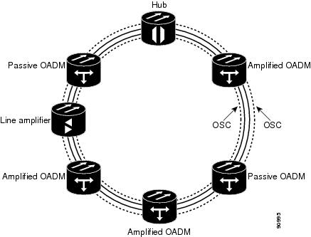
13.2.1.1 Hubbed Traffic Topology
In the hubbed traffic topology (Figure 13-1), a hub node terminates all the DWDM channels. A channel can be provisioned to support protected traffic between the hub node and any node in the ring. Both working and protected traffic use the same wavelength on both sides of the ring. Protected traffic can also be provisioned between any pair of optical add/drop multiplexing (OADM) nodes, except that either the working or the protected path must be regenerated in the hub node.
Protected traffic saturates a channel in a hubbed topology, that is, no channel reuse is possible. However, the same channel can be reused in different sections of the ring by provisioning unprotected multihop traffic. From a transmission point of view, this network topology is similar to two bidirectional point-to-point links with OADM nodes.
For more information about hub nodes, see the “Hub Node” section.
Figure 13-1 Hubbed Traffic Topology
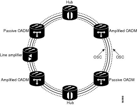
13.2.1.2 Multihubbed Traffic Topology
A multihubbed traffic topology (Figure 13-2) is based on the hubbed traffic topology, except that two or more hub nodes are added. Protected traffic can only be established between the two hub nodes. Protected traffic can be provisioned between a hub node and any OADM node only if the allocated wavelength channel is regenerated through the other hub node. Multihop traffic can be provisioned on this ring. From a transmission point of view, this network topology is similar to two or more point-to-point links with OADM nodes.
Figure 13-2 Multihubbed Traffic Topology
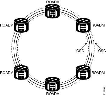
13.2.1.3 Any-to-Any Traffic Topology
The any-to-any traffic topology (Figure 13-3) contains only reconfigurable OADM (ROADM) nodes (with or without optical service channel [OSC] regeneration) or optical amplifier nodes. This topology potentially allows you to route every wavelength from any source to any destination node inside the network.
See the “ROADM Node” section for more information.
Figure 13-3 Any-to-Any Traffic Topology
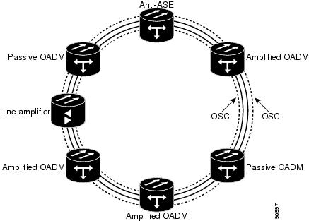
13.2.1.4 Meshed Traffic Topology
The meshed traffic topology (Figure 13-4) does not use hubbed nodes; only amplified and passive OADM nodes are present. Protected traffic can be provisioned between any two nodes; however, the selected channel cannot be reused in the ring. Unprotected multihop traffic can be provisioned in the ring. A meshed ring must be designed to prevent amplified spontaneous emission (ASE) lasing. This is done by configuring a particular node as an anti-ASE node. An anti-ASE node can be created in two ways:
- Equip an OADM node with 32MUX-O cards and 32DMX-O cards. This solution is adopted when the total number of wavelengths deployed in the ring is higher than ten. OADM nodes equipped with 32MUX-O cards and 32DMX-O cards are called full OADM nodes.
- When the total number of wavelengths deployed in the ring is lower than ten, the anti-ASE node is configured by using an OADM node where all the channels that are not terminated in the node are configured as “optical pass-through.” In other words, no channels in the anti-ASE node can travel through the express path of the OADM node.
For more information about OADM nodes, see the “OADM Node” section. For more information about anti-ASE nodes, see the “Anti-ASE Node” section.
Figure 13-4 Meshed Traffic Topology
13.2.2 Linear Networks
Linear configurations are characterized by the use of two terminal nodes, east and west. The 32-channel terminal nodes can be equipped with a 32MUX-O card and a 32DMX-O card, or with a 32WSS card and a 32DMX or 32DMX-O card. The 40-channel terminal nodes can be equipped with a 40-MUX-C card and a 40-DMX-C/40-DMX-CE card, a 40-WSS-C/40-WSS-CE card with a 40-DMX-C/40-DMX-CE card, or a 40-SMR1-C/40-SMR2-C card with a 15216-MD-40-ODD card. OADM or line amplifier nodes can be installed between the two terminal nodes. Only unprotected traffic can be provisioned in a linear configuration. Figure 13-5 shows five ONS 15454 nodes in a linear configuration with an amplified and a passive OADM node.
Figure 13-5 Linear Configuration with an OADM Node
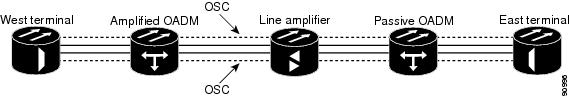
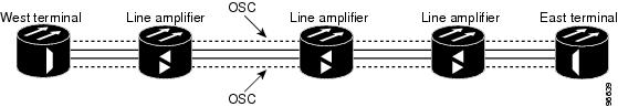
Figure 13-6 shows five ONS 15454 nodes in a linear configuration without an OADM node. See the “Terminal Node” section for more information.
Figure 13-6 Linear Configuration without an OADM Node
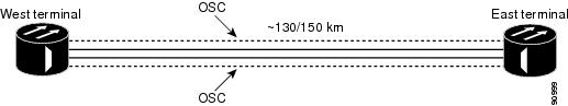
A single-span link is a type of linear configuration characterized by a single-span link with preamplification and post-amplification. A single-span link is also characterized by the use of two terminal nodes, east and west. Only unprotected traffic can be provisioned on a single-span link.
Figure 13-7 shows two ONS 15454s in a single-span link. Eight channels are carried on one span. Single-span link losses apply to OC-192/STM-64 LR ITU cards. The optical performance values are valid assuming that the sum of the OADM passive node insertion losses and the span losses does not exceed 35 dB.
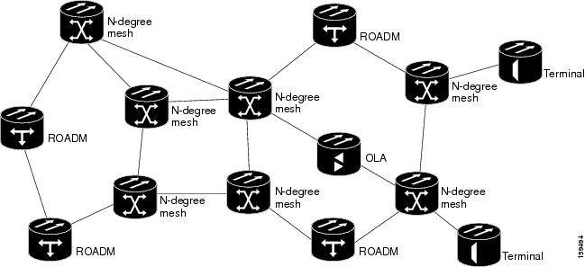
13.2.3 Mesh Networks
A mesh network can be native or multiring. In a native mesh network (Figure 13-8), any combination of four-degree and eight-degree mesh nodes can work together. Four-degree mesh nodes transmit an optical signal in four directions, while an eight-degree mesh node transmits an optical signal in eight directions. For additional information about mesh nodes, see the “Configuring Mesh DWDM Networks” section. The intermediate nodes are ROADM nodes. In a mesh node, all wavelengths can be routed through four (four-degree mesh node) to eight (eight-degree mesh node) different optical line termination ports using a 40-WXC-C, 80-WXC-C, or 40-SMR2-C card without any optical-electrical-optical (OEO) regeneration. It is possible to combine 40-WSS-C/40-WSS-CE, 40-WXC-C, 40-SMR2-C, and 32WSS cards in the same mesh network without impacting system performance. For nodes equipped with 32WSS cards, the maximum system capacity is 32 channels. Terminal sites are connected to the mesh network as a spur.
In a multiring mesh network (Figure 13-9), several rings are connected with four-degree or eight-degree mesh nodes. The intermediate ROADM nodes are equipped with MMU cards. All wavelengths can be routed among two or more rings using a 40-WXC-C or 40-SMR2-C card without any optical-electrical-optical (OEO) regeneration. As in a native mesh network, it is possible to combine 40-WSS-C/40-WSS-CE, 40-WXC-C, 40-SMR2-C, and 32WSS cards in the same multiring network without impacting system performance. For nodes equipped with 32WSS cards, maximum system capacity is limited to 32 channels. A terminal node is connected to a multiring node as a spur.
For information on node configurations for both native mesh and multiring networks, see the “Configuring Mesh DWDM Networks” section.
13.3 Interconnected Rings
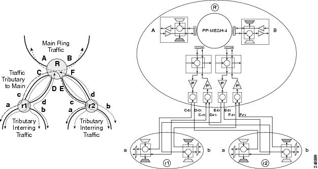
The interconnected ring configuration allows you to connect two different nodes using external ports to allow traffic flow between different subnets. In Figure 13-10, the main ring consists of nodes R, R1, and R2 and the tributary ring consists of nodes r, r1, and r2. It is possible to connect more than one tributary ring to the main ring at the same point. Node R of the main ring can forward wavelengths to the node r of the tributary ring and vice-versa.
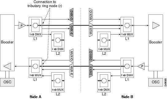
Node R is either a colorless and omni-directional n-degree ROADM node (Figure 13-11) or a two-degree colorless ROADM node (Figure 13-12) equipped with 80-WXC-C cards. See the “Configuring Mesh DWDM Networks” section for more information about colorless and omni-directional n-degree ROADM nodes and two-degree colorless ROADM nodes.
Node r of the tributary ring is a two-degree ROADM node equipped with 40-SMR1-C, 40-SMR2-C, 40-WSS-C, or 40-WSS-CE cards. OTS PPCs are provisioned between the EAD ports of the 80-WXC-C card on node R and the EXP or ADD/DROP ports of the 40-SMR1-C, 40-SMR2-C, 40-WSS-C, or 40-WSS-CE cards on node r. All the nodes are managed by different IP addresses.
Figure 13-10 Interconnected Rings
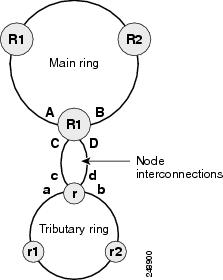
Figure 13-11 Colorless and Omni-directional n- Degree ROADM Node
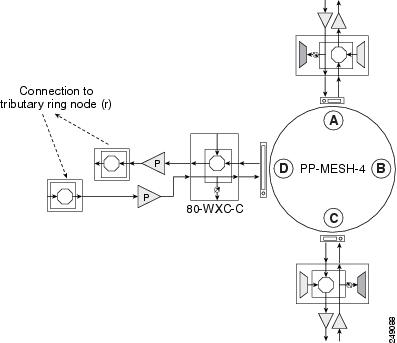
Figure 13-12 Colorless Two-Degree ROADM Node
13.3.1 Interconnected Ring Scenarios
In the following sections, three interconnected ring scenarios are given:
13.3.1.1 Scenario A: Interconnect Traffic from Tributary Ring to Main Ring without Local Add/Drop in the Tributary Ring
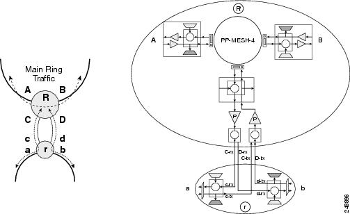
In scenario A-1(Figure 13-13), node R is a three-degree colorless and omni-directional ROADM node and node r is a two-degree 40-SMR1-c based ROADM node. The EAD ports of the 80-WXC-C cards on node R are connected to the ADD/DROP ports of the 40-SMR1-C card on node r. Traffic from node r can be routed to side A or B of node R. Traffic from side a cannot be added or dropped at node r but can be routed to side b using the express path.
Figure 13-13 Interconnected Ring - Scenario A-1
In scenario A-2 (Figure 13-14), node R is a two-degree colorless ROADM node and node r is a two-degree 40-SMR1-C based ROADM node. The EAD ports of the 80-WXC-C cards on node R are connected to the ADD/DROP ports of the 40-SMR1-C card on node r. Traffic from node r can be routed to one side of node R. For example, traffic can be routed from side a to side A or from side b to side B. Traffic from side a cannot be added or dropped at node r but can be routed to side b using the express path.
Figure 13-14 Interconnected Ring - Scenario A-2
13.3.1.2 Scenario B: Interconnect Traffic from Tributary Ring to Main Ring with Local Add/Drop in the Tributary Ring
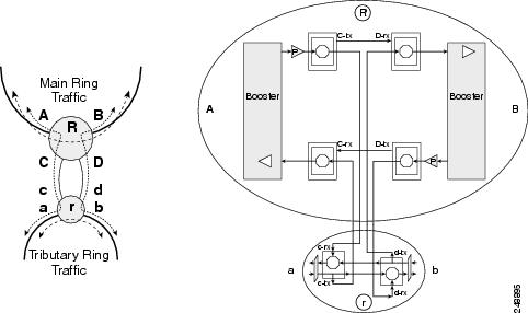
In scenario B-1(Figure 13-15), node R is a three-degree colorless and omni-directional ROADM node and node r is a hub node with two terminal sides equipped with 40-SMR1-C or 40-WSS-C cards. The EAD ports of the 80-WXC-C cards on node R are connected to the EXP ports of the 40-SMR1-C or40-WSS-C card on node r. Traffic from node r can be routed to side A or B of node R. Traffic local to the tributary ring can be added or dropped at node r. For example, traffic from side a can be dropped at node r but cannot be routed to side b since the EXP ports are not available.
Figure 13-15 Interconnected Ring - Scenario B-1
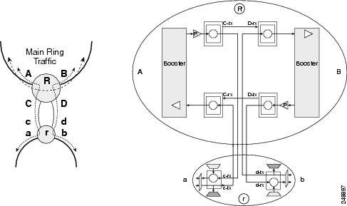
In scenario B-2 (Figure 13-16), node R is a two-degree colorless ROADM node and node r is a hub node with two terminal sides equipped with 40-SMR1-C or 40-WSS-C cards. The EAD ports of the 80-WXC-C cards on node R are connected to the EXP ports of the 40-WSS-C card on node r. Traffic from node r can be routed to one side of node R. For example, traffic can be routed from side a to side A or from side b to side B. Traffic local to the tributary ring can be added or dropped at node r. For example, traffic from side a can be dropped at node r but cannot be routed to side b since the EXP ports are not available.
Figure 13-16 Interconnected Ring - Scenario B-2
13.3.1.3 Scenario C: Interconnect Traffic Between Tributary Rings Using the Main Ring
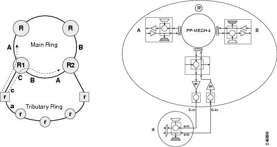
In scenario C-1(Figure 13-17), nodes R1 and R2 are n-degree colorless and omni-directional ROADM nodes. Node r is a terminal site. The EXP ports of the 40-SMR-1C card in node r are connected to the EAD ports of the 80-WXC-C card in nodes R1 and R2. Traffic from node r is routed to side A and B of nodes R1 and R2. Traffic local to the tributary ring can be added or dropped at node r.
Figure 13-17 Interconnected Ring - Scenario C-1
In scenario C-2(Figure 13-18), node R is an n-degree colorless and omni-directional ROADM node with 2 omni-directional sides. Nodes r1 and r2 are hub sites. The ADD/DROP ports of 40-SMR-1-C cards in node r1 and r2 are connected to the EAD ports of 80-WXC-C cards in node R. Traffic can be routed from node r1 to node r2 through node R. Traffic local to the tributary ring can be added or dropped at node r1 and r2.
Figure 13-18 Interconnected Ring - Scenario C-2
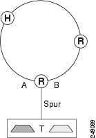
13.4 Spur Configuration
Remote terminal sites can be connected to the main network using a spur. In a spur configuration, the multiplexer (MUX) and demultiplexer (DMX) units associated with one of the sides of node R in the main network (Figure 13-19) are moved to the remote terminal site T. This helps to aggregate traffic from the terminal site. The MUX and DMX units in terminal site T are connected to node R with a single fibre couple. Node R is a n-degree ROADM node equipped with 40-SMR1-C, 40-SMR2-C, or 80-WXC-C cards. Traffic from terminal site T can be routed to side A or side B on node R. Amplification on the spur link is not allowed. PSM is not supported on terminal site T.
13.4.1 Spur Configuration Scenarios
In the following sections, three spur scenarios are provided:
13.4.1.1 Scenario A: Spur Configuration without 15454 Chassis in Remote Terminal T
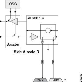
In Figure 13-20, node R is a two-degree ROADM node equipped with 40-SMR1-C card. The remote terminal site T does not have a 15454 chassis and is not shown in the network map in CTC. The terminal site is built using passive MUX and DMX units. All OCHNC circuits originating from 40-SMR1-C on Side A of node R to the remote terminal site are terminated on 40-SMR1-C ADD/DROP ports.
Figure 13-20 Scenario A: Spur Without 15454 Chassis in Remote Terminal T
13.4.1.2 Scenario B: Spur Configuration with Passive MUX and DMX Units in Remote Terminal T
In Figure 13-21, node R is a two-degree ROADM node equipped with 40-SMR1-C card. The terminal site T is built with a 15454 chassis equipped with TXP units and passive MUX and DMX units. Terminal site T is connected to node R on the network map in CTC. All OCHNC circuits originating from 40-SMR1-C on Side A of node R to the remote site are terminated on 40-SMR1-C ADD/DROP ports. OCHCC and OCHTRAIL circuits are supported on the TXP units in terminal site T.
Figure 13-21 Scenario B: Spur With Passive MUX and DMX Units in Remote Terminal T
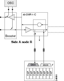
13.4.1.3 Scenario C: Spur Configuration with Active MUX and DMX Units in Remote Terminal T
In Figure 13-22, node R is a two-degree ROADM node equipped with 40-SMR1-C card. The terminal site T is built with a 15454 chassis equipped with TXP units and active MUX and DMX units. Terminal site T is connected to node R on the network map in CTC. DCN extension is supported between the ADD/DROP ports of 40-SMR1-C and the COM ports of the active MUX and DMX units. OCHNC circuits are terminated on the CHAN ports of the MUX and DMX units of terminal site T. OCHCC and OCHTRAIL circuits are supported on the TXP units in terminal site T.
Figure 13-22 Scenario C: Spur with Active MUX and DMX Units in Remote Terminal T
13.5 Network Topologies for the OPT-RAMP-C and OPT-RAMP-CE Cards
The OPT-RAMP-C or OPT-RAMP-CE card can be equipped in any of the following network topologies:
- Open (hubbed) ring network
- Multi-hubbed ring network
- Closed (meshed) ring network
- Any-to-any ring network
- Linear network topology
- Point-to-point linear network topology
- Multi-ring network
- Mesh network
- Hybrid network
For more information about the OPT-RAMP-C or OPT-RAMP-CE card, see Chapter5, “Provision Optical Amplifier Cards”.
13.6 Network Topologies for the PSM Card
The PSM card is supported in the following network topologies:
- The PSM card in a channel protection configuration is supported in all network topologies except linear networks as it is not possible to configure a working and protect path.
- The PSM card in a multiplex section protection configuration is supported in linear point-to-point network topologies.
- The PSM card in a line protection configuration is supported in the following network topologies:
–![]() Linear point-to-point in a single span network (if the OSC card is used).
Linear point-to-point in a single span network (if the OSC card is used).
–![]() Linear point-to-point multispan network when a DCN extension is used (on all spans). In this case, the maximum number of span links can be divided into three according to the DCN extension optical safety requirements.
Linear point-to-point multispan network when a DCN extension is used (on all spans). In this case, the maximum number of span links can be divided into three according to the DCN extension optical safety requirements.
13.7 Optical Performance
This section provides optical performance information for ONS 15454 DWDM networks. The performance data is a general guideline based upon the network topology, node type, client cards, fiber type, number of spans, and number of channels. The maximum number of nodes that can be in an ONS 15454 DWDM network is 16. The DWDM topologies and node types that are supported are shown in Table 13-1 .
|
|
|
|
|
|---|---|---|---|
SMF-281 E-LEAF2 TW-RS3 |
|||
|
|
13.8 Automatic Power Control
The ONS 15454 automatic power control (APC) feature performs the following functions:
- Maintains constant per channel power when desired or accidental changes to the number of channels occur. Constant per channel power increases optical network resilience.
- Compensates for optical network degradation (aging effects).
- Simplifies the installation and upgrade of DWDM optical networks by automatically calculating the amplifier setpoints.
Note![]() APC algorithms manage the optical parameters of the OPT-BST, OPT-PRE, OPT-AMP-17-C, 32DMX, 40-DMX-C, 40-DMX-CE, 40-SMR1-C, 40-SMR2-C, OPT-BST-L, OPT-AMP-L, OPT-AMP-C, and 32DMX-L cards.
APC algorithms manage the optical parameters of the OPT-BST, OPT-PRE, OPT-AMP-17-C, 32DMX, 40-DMX-C, 40-DMX-CE, 40-SMR1-C, 40-SMR2-C, OPT-BST-L, OPT-AMP-L, OPT-AMP-C, and 32DMX-L cards.
Amplifier software uses a control gain loop with fast transient suppression to keep the channel power constant regardless of any changes in the number of channels. Amplifiers monitor the changes to the input power and change the output power proportionately according to the calculated gain setpoint. The shelf controller software emulates the control output power loop to adjust for fiber degradation. To perform this function, the TCC2/TCC2P/TCC3/TNC/TNCE/TSC/TSCE needs to know the channel distribution, which is provided by a signaling protocol, and the expected per channel power, which you can provision. The TCC2/TCC2P/TCC3/TNC/TNCE/TSC/TSCE card compares the actual amplifier output power with the expected amplifier output power and modifies the setpoints if any discrepancies occur.
13.8.1 APC at the Amplifier Card Level
In constant gain mode, the amplifier power out control loop performs the following input and output power calculations, where G represents the gain and t represents time.
In a power-equalized optical system, the total input power is proportional to the number of channels. The amplifier software compensates for any variation of the input power due to changes in the number of channels carried by the incoming signal.
Amplifier software identifies changes in the read input power in two different instances, t1 and t2, as a change in the traffic being carried. The letters m and n in the following formula represent two different channel numbers. Pin/ch represents the input power per channel.
Amplifier software applies the variation in the input power to the output power with a reaction time that is a fraction of a millisecond. This keeps the power constant on each channel at the output amplifier, even during a channel upgrade or a fiber cut.
The per channel power and working mode (gain or power) are set by automatic node setup (ANS). The provisioning is conducted on a per-side basis. A preamplifier or a booster amplifier facing Side i is provisioned using the Side i parameters present in the node database, where i - A, B, C, D, E, F, G, or H.
Starting from the expected per channel power, the amplifiers automatically calculate the gain setpoint after the first channel is provisioned. An amplifier gain setpoint is calculated in order to make it equal to the loss of the span preceding the amplifier itself. After the gain is calculated, the setpoint is no longer changed by the amplifier. Amplifier gain is recalculated every time the number of provisioned channels returns to zero. If you need to force a recalculation of the gain, move the number of channels back to zero.
13.8.2 APC at the Shelf Controller Layer
Amplifiers are managed through software to control changes in the input power caused by changes in the number of channels. The software adjusts the output total power to maintain a constant per channel power value when the number of input channel changes.
Changes in the network characteristics have an impact on the amplifier input power. Changes in the input power are compensated for only by modifying the original calculated gain, because input power changes imply changes in the span loss. As a consequence, the gain to span loss established at amplifier start-up is no longer satisfied, as shown in Figure 13-23.
Figure 13-23 Using Amplifier Gain Adjustment to Compensate for System Degradation
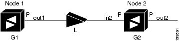
In Figure 13-23, Node 1 and Node 2 are equipped with booster amplifiers and preamplifiers. The input power received at the preamplifier on Node 2 (Pin2) depends on the total power launched by the booster amplifier on Node1, Pout1(n) (where n is the number of channels), and the effect of the span attenuation (L) between the two nodes. Span loss changes due to aging fiber and components or changes in operating conditions. The power into Node 2 is given by the following formula:
The phase gain of the preamplifier on Node 2 (GPre-2) is set during provisioning in order to compensate for the span loss so that the Node 2 preamplifier output power (Pout-Pre-2) is equal to the original transmitted power, as represented in the following formula:
Pout-Pre-2 = L x GPre-2 x Pout1(n)
In cases of system degradation, the power received at Node 2 decreases due to the change of span insertion loss (from L to L'). As a consequence of the preamplifier gain control working mode, the Node 2 preamplifier output power (Pout-Pre-2) also decreases. The goal of APC at the shelf controller layer is simply to detect if an amplifier output change is needed because of changes in the number of channels or to other factors. If factors other than changes in the number of channels occur, APC provisions a new gain at the Node 2 preamplifier (GPre-2') to compensate for the new span loss, as shown in the formula:
GPre-2' = GPre-2 (L/ L') = GPre-2 + [Pout-Pre-2 –Exp(Pout-Pre-2)]
Generalizing on the above relationship, APC is able to compensate for system degradation by adjusting working amplifier gain or variable optical attenuation (VOA) and to eliminate the difference between the power value read by the photodiodes and the expected power value. The expected power values are calculated using:
- Provisioned per channel power value
- Channel distribution (the number of express, add, and drop channels in the node)
- ASE estimation
Channel distribution is determined by the sum of the provisioned and failed channels. Information about provisioned wavelengths is sent to APC on the applicable nodes during circuit creation. Information about failed channels is collected through a signaling protocol that monitors alarms on ports in the applicable nodes and distributes that information to all the other nodes in the network.
ASE calculations purify the noise from the power level reported from the photodiode. Each amplifier can compensate for its own noise, but cascaded amplifiers cannot compensate for ASE generated by preceding nodes. The ASE effect increases when the number of channels decreases; therefore, a correction factor must be calculated in each amplifier of the ring to compensate for ASE build-up.
APC is a network-level feature that is distributed among different nodes. An APC domain is a set of nodes that is controlled by the same instance of APC at the network level. An APC domain optically identifies a portion of the network that can be independently regulated. An optical network can be divided into several different domains, with the following characteristics:
–![]() Cross-connect (XC) termination mesh node
Cross-connect (XC) termination mesh node
- APC domains are shown in both Cisco Transport Controller (CTC) and Transaction Language One (TL1).
- In CTC, domains are shown in the network view and reported as a list of spans. Each span is identified by a node/side pair, for example:
APC Domain Node_1 Side A, Node_4 Side B
+ Span 1: Node_1 Side A, Node_2 Side B
+ Span 2: Node_2 Side A, Node_3 Side B
+ Span 3: Node_3 Side A, Node_4 Side B
Inside a domain, the APC algorithm designates a master node that is responsible for starting APC hourly or every time a new circuit is provisioned or removed. Every time the master node signals APC to start, gain and VOA setpoints are evaluated on all nodes in the network. If corrections are needed in different nodes, they are always performed sequentially following the optical paths starting from the master node.
APC corrects the power level only if the variation exceeds the hysteresis thresholds of +/– 0.5 dB. Any power level fluctuation within the threshold range is skipped since it is considered negligible. Because APC is designed to follow slow time events, it skips corrections greater than 3 dB. This is the typical total aging margin that is provisioned during the network design phase. After you provision the first channel or the amplifiers are turned up for the first time, APC does not apply the 3 dB rule. In this case, APC corrects all the power differences to turn up the node.
To avoid large power fluctuations, APC adjusts power levels incrementally. The maximum power correction is +/– 0.5 dB. This is applied to each iteration until the optimal power level is reached. For example, a gain deviation of 2 dB is corrected in four steps. Each of the four steps requires a complete APC check on every node in the network. APC can correct up to a maximum of 3 dB on an hourly basis. If degradation occurs over a longer time period, APC compensates for it by using all margins that you provision during installation.
If no margin is available, adjustments cannot be made because setpoints exceed the ranges. APC communicates the event to CTC, Cisco Transport Manager (CTM), and TL1 through an APC Fail condition. APC clears the APC fail condition when the setpoints return to the allowed ranges.
APC can be manually disabled. In addition, APC automatically disables itself when:
- An Hardware Fail (HF) alarm is raised by any card in any of the domain nodes.
- A Mismatch Equipment Alarm (MEA) is raised by any card in any of the domain nodes.
- An Improper Removal (IMPROPRMVL) alarm is raised by any card in any of the domain nodes.
- Gain Degrade (GAIN-HDEG), Power Degrade (OPWR-HDEG), and Power Fail (PWR-FAIL) alarms are raised by the output port of any amplifier card in any of the domain nodes.
- A VOA degrade or fail alarm is raised by any of the cards in any of the domain nodes.
- The signaling protocol detects that one of the APC instances in any of the domain nodes is no longer reachable.
The APC state (Enable/Disable) is located on every node and can be retrieved by the CTC or TL1 interface. If an event that disables APC occurs in one of the network nodes, APC is disabled on all the other nodes and the APC state changes to DISABLE - INTERNAL. The disabled state is raised only by the node where the problem occurred to simplify troubleshooting.
APC raises the following minor, non-service-affecting alarms at the port level in CTC, TL1, and Simple Network Management Protocol (SNMP):
- APC Out of Range—APC cannot assign a new setpoint for a parameter that is allocated to a port because the new setpoint exceeds the parameter range.
- APC Correction Skipped—APC skipped a correction to one parameter allocated to a port because the difference between the expected and current values exceeds the +/– 3 dB security range.
- APC Disabled—APC is disabled, either by a user or internal action.
After the error condition is cleared, the signaling protocol enables APC on the network and the APC DISABLE - INTERNAL condition is cleared. Because APC is required after channel provisioning to compensate for ASE effects, all optical channel network connection (OCHNC) and optical channel client connection (OCHCC) circuits that you provision during the disabled APC state are kept in the Out-of-Service and Autonomous, Automatic In-Service (OOS-AU,AINS) (ANSI) or Unlocked-disabled,automaticInService (ETSI) service state until APC is enabled. OCHNCs and OCHCCs automatically go into the In-Service and Normal (IS-NR) (ANSI) or Unlocked-enabled (ETSI) service state only after APC is enabled.
13.8.3 APC in a Raman Node with Post-Amplifiers
After the Raman gain is calculated and the Raman and OSC links are turned up, APC performs the following sequence of events:
1.![]() The line amplifier that is downstream of the OPT-RAMP-C or OPT-RAMP-CE card is the first card that the APC regulates. The line amplifier is configured as OPT-PRE in ROADM nodes or as OPT-LINE in OLA nodes.
The line amplifier that is downstream of the OPT-RAMP-C or OPT-RAMP-CE card is the first card that the APC regulates. The line amplifier is configured as OPT-PRE in ROADM nodes or as OPT-LINE in OLA nodes.
After Automatic Power Reduction (APR) is implemented, the working mode of the line amplifier is forced to Control Power and remains in the same mode until all the node regulations are complete. This ensures that the calculation of the Gain setpoint is accurate during Raman node internal regulations. The amplifier signal output power is regulated using the Power (LINE-TX port) setpoint.
2.![]() The APC changes the Gain setpoint of the embedded EDFA to reach the value that is equal to Power (DC-TX port) value multiplied by the number of active channels.
The APC changes the Gain setpoint of the embedded EDFA to reach the value that is equal to Power (DC-TX port) value multiplied by the number of active channels.
The APC can set the Gain setpoint of the embedded EDFA (G EDFA) in the following ranges:
–![]() OPT-RAMP-C 10 dB < G EDFA < 18 dB
OPT-RAMP-C 10 dB < G EDFA < 18 dB
–![]() OPT-RAMP-CE 7 dB < G EDFA < 13 dB
OPT-RAMP-CE 7 dB < G EDFA < 13 dB
The internal VOA is set to 0 dB on the DC-TX port. The VOA attenuation is set to zero because the actual DCU insertion loss is unknown until the optical payload is transmitted to the card. Therefore a proper attenuation setpoint cannot be estimated. When the attenuation value is set to 0 dB, it ensures that the system turns up in any circumstance.
3.![]() After the G EDFA is set, APC regulates the power on the VOA (DC-TX port) of the OPT-RAMP-C or OPT-RAMP-CE card to match the target Power (COM-TX port) value, and accounts for the actual DCU loss.
After the G EDFA is set, APC regulates the power on the VOA (DC-TX port) of the OPT-RAMP-C or OPT-RAMP-CE card to match the target Power (COM-TX port) value, and accounts for the actual DCU loss.
4.![]() After Steps 2 and 3 are completed, the optical power received on the line amplifier that is downstream of the OPT-RAMP-C or OPT-RAMP-CE card becomes fully regulated and stable. The Raman tilt and G EDFA tilt are fixed. The APC regulates the value of the Total Power on the LINE-TX port of the line amplifier and accounts for the ASE noise contribution.
After Steps 2 and 3 are completed, the optical power received on the line amplifier that is downstream of the OPT-RAMP-C or OPT-RAMP-CE card becomes fully regulated and stable. The Raman tilt and G EDFA tilt are fixed. The APC regulates the value of the Total Power on the LINE-TX port of the line amplifier and accounts for the ASE noise contribution.
5.![]() After the value of the total power on the line amplifier becomes a stable value, APC stops the regulations and the automatic gain calculation procedure is completed on the line amplifier card. The TCC checks if the gain setpoint is within range and eventually changes the working mode of the OPT-RAMP-C or OPT-RAMP-CE card to Gain Control mode.
After the value of the total power on the line amplifier becomes a stable value, APC stops the regulations and the automatic gain calculation procedure is completed on the line amplifier card. The TCC checks if the gain setpoint is within range and eventually changes the working mode of the OPT-RAMP-C or OPT-RAMP-CE card to Gain Control mode.
Note![]() If the value of the Raman Total Power was manually provisioned or set by ANS instead of the Raman installation wizard, a fiber cut recovery procedure is automatically performed, before APC regulation.
If the value of the Raman Total Power was manually provisioned or set by ANS instead of the Raman installation wizard, a fiber cut recovery procedure is automatically performed, before APC regulation.
13.8.4 APC in a Raman Node without Post-Amplifiers
After the Raman gain is calculated and the Raman and OSC links are turned up, APC performs the following sequence of events:
1.![]() The APC adjusts the VOA attenuation of the OPT-RAMP-C or OPT-RAMP-CE card if the Total Power (LINE-TX port) does not match the expected value that is equal to the maximum power multiplied by the number of active channels. The VOA attenuation value on the OPT-RAMP-C or OPT-RAMP-CE cards is set to 15 dB. This value ensures that the system turns up in any circumstance.
The APC adjusts the VOA attenuation of the OPT-RAMP-C or OPT-RAMP-CE card if the Total Power (LINE-TX port) does not match the expected value that is equal to the maximum power multiplied by the number of active channels. The VOA attenuation value on the OPT-RAMP-C or OPT-RAMP-CE cards is set to 15 dB. This value ensures that the system turns up in any circumstance.
2.![]() If a short span is used, the embedded EDFA in the downstream node receives excessive input power and is unable to maintain proper per channel power value on its output port as the number of channels increase. The APC detects output power saturation on the EDFA of the downstream node and increases the value of the VOA attenuation on the upstream node thereby reducing the Power (LINE-TX port) value.
If a short span is used, the embedded EDFA in the downstream node receives excessive input power and is unable to maintain proper per channel power value on its output port as the number of channels increase. The APC detects output power saturation on the EDFA of the downstream node and increases the value of the VOA attenuation on the upstream node thereby reducing the Power (LINE-TX port) value.
13.8.5 Managing APC
The APC status is indicated by four APC states shown in the node view status area:
- Enabled—APC is enabled.
- Disabled—APC was disabled manually by a user.
- Disable - Internal—APC has been automatically disabled for an internal cause.
- Not Applicable—The node is provisioned to Not DWDM, which does not support APC.
You can view the APC information and disable and enable APC manually on the Maintenance > DWDM > APC tab.

The APC subtab provides the following information:
- Position—The slot number, card, and port for which APC information is shown.
- Last Modification—Date and time APC parameter setpoints were last modified.
- Parameter—The parameter that APC last modified.
- Last Check—Date and time APC parameter setpoints were last verified.
- Side—The side where the APC information for the card and port is shown.
- State—The APC state.
A wrong use of maintenance procedures (for example, the procedures to be applied in case of fiber cut repair) can lead the system to raise the APC Correction Skipped alarm. The APC Correction Skipped alarm strongly limits network management (for example, a new circuit cannot be turned into IS). The Force APC Correction button helps to restore normal conditions by clearing the APC Correction Skipped alarm.
The Force APC Correction button must be used under the Cisco TAC surveillance since its misuse can lead to traffic loss.
The Force APC Correction button is available in the Card View > Maintenance > APC tab pane in CTC for the following cards:
13.9 Power Side Monitoring
DWDM nodes allow you to view bar graphs of the input and output spectrum on each optical side of the node in the Maintenance > DWDM > Side Power Monitoring tab. When you place the mouse over each wavelength in the bar chart, the power level and wavelength type are displayed. This feature is available on nodes that are installed with cards with Optical Channel Monitoring (OCM) capability.
The Side Power Monitoring panel is divided into Optical Side X subtabs, where X is the optical side. The number of subtabs is equal to the number of optical sides in the node. Each subtab displays two bar graphs.
The IN bar graph displays the optical spectrum at the input port (LINE-RX) of the side in the direction from the fiber to the node provided the OCM functionality is available on this port else the graph displays the aggregate signal spectral distribution on the first port in the signal flow (indicated in the title of the bar chart) that is downstream of the LINE-RX port where an OCM measurement is available (For example, in node using a booster and a 40-SMR1-C card, the measurement is done on the EXP port of the 40-SMR1-C card).
The OUT bar graph displays the optical spectrum at the output port (LINE-TX) of the side in the direction from the node to the fiber provided the OCM functionality is available on this port else the graph displays the aggregate signal spectral distribution on the first port (indicated in the title of the bar chart) that is upstream of the LINE-TX port where an OCM measurement is available.
Note![]() Depending on the side layout, the LINE-TX port (output) and the LINE-RX port (input) of the card facing the fiber cannot measure the optical spectrum in a reliable manner if the OCM functionality is not available on these ports.
Depending on the side layout, the LINE-TX port (output) and the LINE-RX port (input) of the card facing the fiber cannot measure the optical spectrum in a reliable manner if the OCM functionality is not available on these ports.
When you place the mouse over each wavelength in the bar chart, the power level and the wavelength type (local ADD/DROP or EXPRESS) are displayed as a ScreenTip.
- IN graph: The Screen Tip displays the destination side of each wavelength. The wavelength is either dropped locally or expressed to another side (see Figure 13-24).
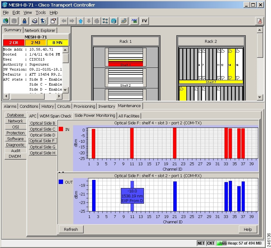
- OUT graph: The Screen Tip displays the source side of each wavelength. The wavelength is either added locally or expressed from another side (see Figure 13-25).
Figure 13-24 Side Power Monitoring Subtab
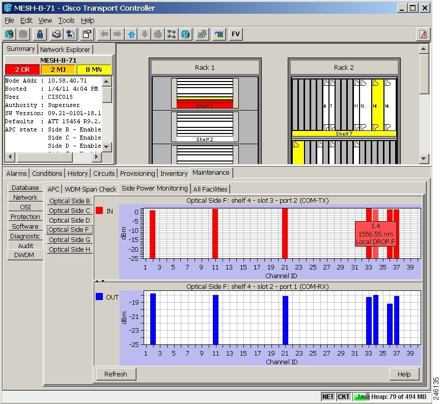
Figure 13-25 Side Power Monitoring Subtab
13.10 Span Loss Verification
Span loss measurements can be performed from the Maintenance > DWDM > WDM Span Check tab. The CTC span check compares the far-end OSC power with the near-end OSC power. A Span Loss Out of Range condition is raised when the measured span loss is higher than the maximum expected span loss. It is also raised when the measured span loss is lower than the minimum expected span loss and the difference between the minimum and maximum span loss values is greater than 1 dB. The minimum and maximum expected span loss values are calculated by Cisco TransportPlanner for the network and imported into CTC. However, you can manually change the minimum and expected span loss values.
CTC span loss measurements provide a quick span loss check and are useful whenever changes to the network occur, for example after you install equipment or repair a broken fiber. CTC span loss measurement resolutions are:
- +/– 1.5 dB for measured span losses between 0 and 25 dB
- +/– 2.5 dB for measured span losses between 25 and 38 dB
For ONS 15454 span loss measurements with higher resolutions, an optical time domain reflectometer (OTDR) must be used.
Note![]() From Software Release 9.0 onwards, span loss measurement is performed using C-band channels (whenever available), instead of OSC signals. Software Release 9.0 is not interoperable with earlier releases that are only OSC-based. Therefore, span loss measurement cannot be done on a span if the adjacent nodes are running different software releases; for example one node running Software Release 8.0 or an earlier release and the second node running Software Release 9.0 or a later release.
From Software Release 9.0 onwards, span loss measurement is performed using C-band channels (whenever available), instead of OSC signals. Software Release 9.0 is not interoperable with earlier releases that are only OSC-based. Therefore, span loss measurement cannot be done on a span if the adjacent nodes are running different software releases; for example one node running Software Release 8.0 or an earlier release and the second node running Software Release 9.0 or a later release.
13.10.1 Span Loss Measurements on Raman Links
Span loss measurement when Raman amplification is active is less accurate than a standard link as it is based on a mathematical formula that uses the Raman noise and Raman gain.
Span loss on a Raman link is measured in the following states:
- Automatically during Raman link setup (without Raman amplification)
- Automatically during fiber cut restore (without Raman amplification)
- Periodically or upon request (with Raman amplification)
CTC reports three values in the Maintenance > DWDM > WDM Span Check tab:
- Current Span Measure with Raman—Estimated span loss with Raman pump turned ON.
- Wizard Span Measure with Raman Off—Span loss with Raman pump turned OFF, during Raman installation.
- Last Span Measure with Raman—Span loss after a fiber cut restoration procedure.
Measurements are performed automatically on an hourly basis.
A Span Loss Out of Range condition is raised under the following conditions:
- Span loss is greater than the maximum expected span loss + resolution
- Span loss is less than the minimum expected span loss – resolution
The minimum and maximum expected span loss values are calculated by Cisco Transport Planner for the network and imported into CTC. However, you can manually change the minimum and maximum expected span loss values.
Note![]() During Raman installation using a wizard, the Span Loss Out of Range alarm is not raised when the out of range condition is raised. In such a case, the wizard fails and an error message is displayed, and the span is not tuned.
During Raman installation using a wizard, the Span Loss Out of Range alarm is not raised when the out of range condition is raised. In such a case, the wizard fails and an error message is displayed, and the span is not tuned.
CTC span loss measurements provide a quick span loss check and are useful whenever changes to the network occur, for example after you install equipment or repair a broken fiber. CTC span loss measurement resolutions are:
13.11 Network Optical Safety
If a fiber break occurs on the network, automatic laser shutdown (ALS) automatically shuts down the OSCM and OSC-CSM OSC laser output power and the optical amplifiers contained in the OPT-BST, OPT-BST-E, OPT-BST-L, OPT-AMP-L, OPT-AMP-C, OPT-AMP-17-C, OPT-RAMP-C, OPT-RAMP-CE, 40-SMR1-C, and 40-SMR2-C cards, and the TX VOA in the protect path of the PSM card (in line protection configuration only). (Instead, the PSM active path will use optical safety mechanism implemented by the booster amplifier or OSC-CSM card that are mandatory in the line protection configuration.)
The Maintenance > ALS tab in CTC card view provide the following ALS management options for OSCM, OSC-CSM, OPT-BST, OPT-BST-E, OPT-BST-L, OPT-AMP-L, OPT-AMP-C, OPT-AMP-17-C, OPT-RAMP-C, OPT-RAMP-CE, 40-SMR1-C, 40-SMR2-C, and PSM (on the protect path, only in line protection configuration) cards:
- Disable—ALS is off. The OSC laser transmitter and optical amplifiers are not automatically shut down when a traffic outage loss of signal (LOS) occurs.
- Auto Restart—ALS is on. The OSC laser transmitter and optical amplifiers automatically shut down when traffic outages (LOS) occur. It automatically restarts when the conditions that caused the outage are resolved. Auto Restart is the default ALS provisioning for OSCM, OSC-CSM, OPT-BST, OPT-BST-E, OPT-BST-L, OPT-AMP-L, OPT-AMP-C, OPT-AMP-17-C, OPT-RAMP-C, OPT-RAMP-CE, 40-SMR1-C, 40-SMR2-C, and PSM (on the protect path, only in line protection configuration) cards.
- Manual Restart—ALS is on. The OSC laser transmitter and optical amplifiers automatically shut down when traffic outages (LOS) occur. However, the laser must be manually restarted when conditions that caused the outage are resolved.
- Manual Restart for Test—Manually restarts the OSC laser transmitter and optical amplifiers for testing.
13.11.1 Automatic Laser Shutdown
When ALS is enabled on OPT-BST, OPT-BST-E, OPT-BST-L, OPT-AMP-L, OPT-AMP-C, OPT-AMP-17-C, OPT-RAMP-C, OPT-RAMP-CE, 40-SMR1-C, 40-SMR2-C, PSM (on the protect path, only in line protection configuration), OSCM, OSC-CSM, TNC, and TNCE cards, a network safety mechanism will occur in the event of a system failure. ALS provisioning is also provided on the transponder (TXP) and muxponder (MXP) cards. However, if a network uses ALS-enabled OPT-BST, OPT-BST-E, OPT-BST-L, OPT-AMP-L, OPT-AMP-C, OPT-AMP-17-C, OPT-RAMP-C, OPT-RAMP-CE, 40-SMR1-C, 40-SMR2-C, PSM (on the protect path, only in line protection configuration), OSCM, and OSC-CSM cards, ALS does not need to be enabled on the TXP cards or MXP cards. ALS is disabled on TXP and MXP cards by default and the network optical safety is not impacted.
If TXP and MXP cards are connected directly to each other without passing through a DWDM layer, ALS should be enabled on them. The ALS protocol goes into effect when a fiber is cut, enabling some degree of network point-to-point bidirectional traffic management between the cards.
If ALS is disabled on the OPT-BST, OPT-BST-E, OPT-BST-L, OPT-AMP-L, OPT-AMP-C, OPT-AMP-17-C, OPT-RAMP-C, OPT-RAMP-CE, 40-SMR1-C, 40-SMR2-C, PSM (on the protect path, only in line protection configuration), OSCM, and OSC-CSM cards (the DWDM network), ALS can be enabled on the TXP and MXP cards to provide laser management in the event of a fiber break in the network between the cards.
13.11.2 Automatic Power Reduction
Automatic power reduction (APR) is controlled by the software and is not user configurable. During amplifier restart after a system failure, the amplifier (OPT-BST, for example) operates in pulse mode and an APR level is activated so that the Hazard Level 1 power limit is not exceeded. This is done to ensure personnel safety.
When a system failure occurs (cut fiber or equipment failure, for example) and ALS Auto Restart is enabled, a sequence of events is placed in motion to shut down the amplifier laser power, then automatically restart the amplifier after the system problem is corrected. As soon as a loss of optical payload and OSC is detected at the far end, the far-end amplifier shuts down. The near-end amplifier then shuts down because it detects a loss of payload and the OSC shuts down due to the far-end amplifier shutdown. At this point, the near end attempts to establish communication to the far end using the OSC laser transmitter. To do this, the OSC emits a two-second pulse at very low power (maximum of 0 dBm) and waits for a similar two-second pulse in response from the far-end OSC laser transmitter. If no response is received within 100 seconds, the near end tries again. This process continues until the near end receives a two-second response pulse from the far end, indicating the system failure is corrected and full continuity in the fiber between the two ends exists.
After the OSC communication is established, the near-end amplifier is configured by the software to operate in pulse mode at a reduced power level. It emits a nine-second laser pulse with an automatic power reduction to +8 dBm. (For 40-SMR1-C and 40-SMR2-C cards, the pulse is not +8 dBm but it is the per channel power setpoint.) This level assures that Hazard Level 1 is not exceeded, for personnel safety, even though the establishment of successful OSC communication is assurance that any broken fiber is fixed. If the far-end amplifier responds with a nine-second pulse within 100 seconds, both amplifiers are changed from pulse mode at reduced power to normal operating power mode.
For a direct connection between TXP or MXP cards, when ALS Auto Restart is enabled and the connections do not pass through a DWDM layer, a similar process takes place. However, because the connections do not go through any amplifier or OSC cards, the TXP or MXP cards attempt to establish communication directly between themselves after a system failure. This is done using a two-second restart pulse, in a manner similar to that previously described between OSCs at the DWDM layer. The power emitted during the pulse is below Hazard Level 1.
APR is also implemented on the PSM card (on the protect path, only in line protection configuration). In the PSM line protection configuration, when a system failure occurs on the working path (cut fiber or equipment failure, for example), the ALS and APR mechanisms are implemented by the booster amplifier or the OSC-CSM card. Alternately, when a system failure occurs on the protect path, and ALS Auto Restart is enabled on the PSM card, a sequence of events is placed in motion to shut down the TX VOA on the protect path, and then automatically restart it after the system failure is corrected. During protect path restart, the TX VOA on the protect path operates in pulse mode and limits the power to maximum +8 dBm so that the Hazard Level 1 power limit is not exceeded on protect TX path.
When ALS is disabled, the warning Statement 1056 is applicable.

Warning Invisible laser radiation may be emitted from the end of the unterminated fiber cable or connector. Do not view directly with optical instruments. Viewing the laser output with certain optical instruments (for example, eye loupes, magnifiers, and microscopes) within a distance of 100 mm may pose an eye hazard. Statement 1056
Note![]() If you must disable ALS, verify that all fibers are installed in a restricted location. Enable ALS immediately after finishing the maintenance or installation process.
If you must disable ALS, verify that all fibers are installed in a restricted location. Enable ALS immediately after finishing the maintenance or installation process.
Note![]() For the line amplifier to start up automatically, disable the ALS on the terminal node that is unidirectional.
For the line amplifier to start up automatically, disable the ALS on the terminal node that is unidirectional.
13.11.3 Network Optical Safety on OPT-RAMP-C and OPT-RAMP-CE Cards
Optical safety on the OPT-RAMP-C and OPT-RAMP-CE cards is implemented in the RAMAN-TX and COM-TX ports. RAMAN-TX will report safety settings associated to the Raman pump while the COM-TX port will report safety settings associated with the embedded EDFA.
13.11.3.1 RAMAN-TX Settings on Raman Pump
The Raman pump is automatically turned off as soon as the LOS alarm is detected on the LINE-RX port. The Raman pump is automatically turned on at APR power every 100 secs for a duration of 9 seconds at a pulse power of at 8 dBm, as soon as the LINE-RX port is set to IS-NR/unlocked-enabled.
Note![]() Optical safety cannot be disabled on the OPT-RAMP-C and OPT-RAMP-CE cards and cannot be disabled on OSCM cards when connected to a OPT-RAMP-C or OPT-RAMP-CE card.
Optical safety cannot be disabled on the OPT-RAMP-C and OPT-RAMP-CE cards and cannot be disabled on OSCM cards when connected to a OPT-RAMP-C or OPT-RAMP-CE card.
The system periodically verifies if the signal power is present on the LINE-RX port. If signal power is present, the following occurs:
The Raman power is then moved to setpoint if power is detected for more than 10 seconds. During Automatic Laser Restart (ALR) the safety is enabled. The laser is automatically shut down if LOS is detected on the receiving fiber. In general Raman pump turns on only when Raman signals are detected. However, the Raman pump can be configured to turn on to full power even when OSC power is detected for more than 9 seconds on OSC-RX port.
13.11.3.2 COM-TX Safety Setting on EDFA
EDFA is shutdown automatically under the following conditions:
If EDFA was shut down because of Raman pump shut down, the EDFA restarts by automatically turning on the EDFA lasers as soon as the Raman loop is closed.
- Pulse duration: 9 seconds
- Pulse power: 8 dB (maximum APR power foreseen by safety regulation)
- Exit condition: Received power detected on the DC-RX port at the end of APR pulse. If power is detected on DC-RX (so DCU is connected) EDFA moves to set-point; otherwise, it keeps 9 dB as the output power at restart
- EDFA moves to the power setpoint when power is detected on the DC-RX port.
If EDFA was shutdown because of an LOS-P alarm. The EDFA restarts by automatically turning on the EDFA laser as soon as an LOS-P alarm on the COM-RX port is cleared, and the Raman loop is closed.
- Pulse duration: 9 seconds
- Pulse power: 8 dB (maximum APR power foreseen by safety regulation)
- Exit condition: Received power detected on the LINE-RX port at the end of the APR pulse
Warning All ONS 15454 users must be properly trained on laser safety hazards in accordance with IEC 60825-2, or ANSI Z136.1.
13.11.4 Fiber Cut Scenarios
In the following paragraphs, four ALS scenarios are given:
- Scenario 1: Fiber Cut in Nodes Using OPT-BST/OPT-BST-E Cards
- Scenario 2: Fiber Cut in Nodes Using OSC-CSM Cards
- Scenario 3: Fiber Cut in Nodes Using OPT-BST-L Cards
- Scenario 4: Fiber Cut in Nodes Using OPT-AMP-L, OPT-AMP-C, OPT-AMP-17-C (OPT-LINE Mode), 40-SMR1-C, or 40-SMR2-C Cards
- Scenario 5: Fiber Cut in Nodes Using DCN Extension
- Scenario 6: Fiber Cut in Nodes Using OPT-RAMP-C or OPT-RAMP-CE Cards
- Scenario 7: Fiber Cut in Optical Line Amplifier Nodes Using OPT-RAMP-C or OPT-RAMP-CE Cards
13.11.4.1 Scenario 1: Fiber Cut in Nodes Using OPT-BST/OPT-BST-E Cards
Figure 13-26 shows nodes using OPT-BST/OPT-BST-E cards with a fiber cut between them.
Figure 13-26 Nodes Using OPT-BST/OPT-BST-E Cards
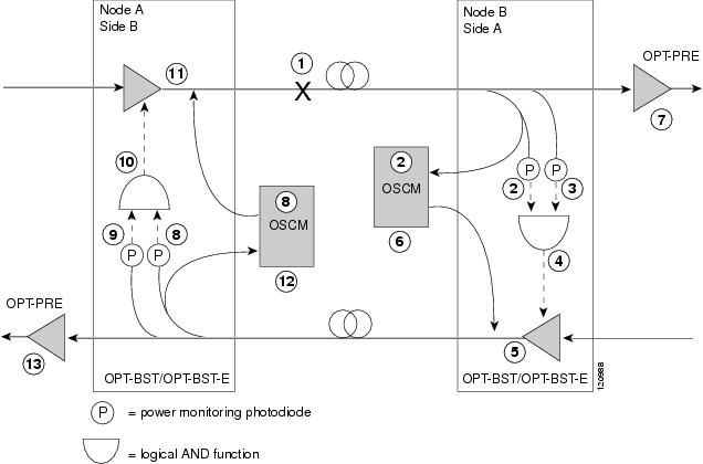
Two photodiodes at Node B monitor the received signal strength for the optical payload and OSC signals. When the fiber is cut, an LOS is detected at both of the photodiodes. The AND function then indicates an overall LOS condition, which causes the OPT-BST/OPT-BST-E transmitter, OPT-PRE transmitter, and OSCM lasers to shut down. This in turn leads to an LOS for both the optical payload and OSC at Node A, which causes Node A to turn off the OSCM, OPT-PRE transmitter, and OPT-BST/OPT-BST-E transmitter lasers. The sequence of events after a fiber cut is as follows (refer to the numbered circles in Figure 13-26):
2.![]() The Node B power monitoring photodiode detects a Loss of Incoming Payload (LOS-P) on the OPT-BST/OPT-BST-E card. Refer to the Cisco ONS 15454 DWDM Troubleshooting Guide .
The Node B power monitoring photodiode detects a Loss of Incoming Payload (LOS-P) on the OPT-BST/OPT-BST-E card. Refer to the Cisco ONS 15454 DWDM Troubleshooting Guide .
3.![]() On the OPT-BST/OPT-BST-E card, the simultaneous LOS-O and LOS-P detection triggers a command to shut down the amplifier. CTC reports an LOS alarm (loss of continuity), while LOS-O and LOS-P are demoted. Refer to the Cisco ONS 15454 DWDM Troubleshooting Guide .
On the OPT-BST/OPT-BST-E card, the simultaneous LOS-O and LOS-P detection triggers a command to shut down the amplifier. CTC reports an LOS alarm (loss of continuity), while LOS-O and LOS-P are demoted. Refer to the Cisco ONS 15454 DWDM Troubleshooting Guide .
4.![]() The OPT-BST/OPT-BST-E card amplifier is shut down within one second.
The OPT-BST/OPT-BST-E card amplifier is shut down within one second.
5.![]() The OSCM laser is shut down.
The OSCM laser is shut down.
6.![]() The OPT-PRE card automatically shuts down due to a loss of incoming optical power.
The OPT-PRE card automatically shuts down due to a loss of incoming optical power.
7.![]() The Node A power monitoring photodiode detects a LOS-O on the OPT-BST/OPT-BST-E card and the OSCM card detects a LOS (OC3) at the SONET layer. Refer to the Cisco ONS 15454 DWDM Troubleshooting Guide .
The Node A power monitoring photodiode detects a LOS-O on the OPT-BST/OPT-BST-E card and the OSCM card detects a LOS (OC3) at the SONET layer. Refer to the Cisco ONS 15454 DWDM Troubleshooting Guide .
8.![]() The Node A power monitoring photodiode detects a LOS-P on the OPT-BST/OPT-BST-E card. Refer to the Cisco ONS 15454 DWDM Troubleshooting Guide .
The Node A power monitoring photodiode detects a LOS-P on the OPT-BST/OPT-BST-E card. Refer to the Cisco ONS 15454 DWDM Troubleshooting Guide .
9.![]() On the OPT-BST/OPT-BST-E, the simultaneous LOS-O and LOS-P detection triggers a command to shut down the amplifier. CTC reports an LOS alarm (loss of continuity), while LOS-O and LOS-P are demoted. Refer to the Cisco ONS 15454 DWDM Troubleshooting Guide .
On the OPT-BST/OPT-BST-E, the simultaneous LOS-O and LOS-P detection triggers a command to shut down the amplifier. CTC reports an LOS alarm (loss of continuity), while LOS-O and LOS-P are demoted. Refer to the Cisco ONS 15454 DWDM Troubleshooting Guide .
10.![]() The OPT-BST/OPT-BST-E card amplifier is shut down within one second.
The OPT-BST/OPT-BST-E card amplifier is shut down within one second.
11.![]() The OSCM laser is shut down.
The OSCM laser is shut down.
12.![]() The Node A OPT-PRE card automatically shuts down due to a loss of incoming optical power.
The Node A OPT-PRE card automatically shuts down due to a loss of incoming optical power.
When the fiber is repaired, either an automatic or manual restart at the Node A OPT-BST/OPT-BST-E transmitter or at the Node B OPT-BST/OPT-BST-E transmitter is required. A system that has been shut down is reactivated through the use of a restart pulse. The pulse is used to signal that the optical path has been restored and transmission can begin. For example, when the far end, Node B, receives a pulse, it signals to the Node B OPT-BST/OPT-BST-E transmitter to begin transmitting an optical signal. The OPT-BST/OPT-BST-E receiver at Node A receives that signal and signals the Node A OPT-BST/OPT-BST-E transmitter to resume transmitting.
Note![]() During a laser restart pulse, APR ensures that the laser power does not exceed Class 1 limits. See the “Automatic Power Reduction” section for more information about APR.
During a laser restart pulse, APR ensures that the laser power does not exceed Class 1 limits. See the “Automatic Power Reduction” section for more information about APR.
13.11.4.2 Scenario 2: Fiber Cut in Nodes Using OSC-CSM Cards
Figure 13-27 shows nodes using OSC-CSM cards with a fiber cut between them.
Figure 13-27 Nodes Using OSC-CSM Cards
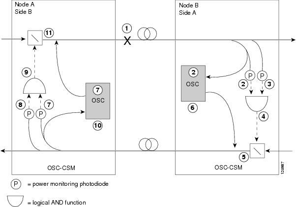
Two photodiodes at the Node B OSC-CSM card monitor the received signal strength for the received optical payload and OSC signals. When the fiber is cut, LOS is detected at both of the photodiodes. The AND function then indicates an overall LOS condition, which causes the Node B OSC laser to shut down and the optical switch to block traffic. This in turn leads to LOS for both the optical payload and OSC signals at Node A, which causes Node A to turn off the OSC laser and the optical switch to block outgoing traffic. The sequence of events after a fiber cut is as follows (refer to the numbered circles in Figure 13-27):
2.![]() The Node B power monitoring photodiode detects a LOS-P on the OSC-CSM card. Refer to the Cisco ONS 15454 DWDM Troubleshooting Guide .
The Node B power monitoring photodiode detects a LOS-P on the OSC-CSM card. Refer to the Cisco ONS 15454 DWDM Troubleshooting Guide .
3.![]() On the OSC-CSM, the simultaneous LOS-O and LOS-P detection triggers a change in the position of the optical switch. CTC reports a LOS alarm (loss of continuity), while LOS-O and LOS-P are demoted. Refer to the Cisco ONS 15454 DWDM Troubleshooting Guide .
On the OSC-CSM, the simultaneous LOS-O and LOS-P detection triggers a change in the position of the optical switch. CTC reports a LOS alarm (loss of continuity), while LOS-O and LOS-P are demoted. Refer to the Cisco ONS 15454 DWDM Troubleshooting Guide .
4.![]() The optical switch blocks outgoing traffic.
The optical switch blocks outgoing traffic.
5.![]() The OSC laser is shut down.
The OSC laser is shut down.
6.![]() The Node A power monitoring photodiode detects a LOS-O on the OSC-CSM card. Refer to the Cisco ONS 15454 DWDM Troubleshooting Guide .
The Node A power monitoring photodiode detects a LOS-O on the OSC-CSM card. Refer to the Cisco ONS 15454 DWDM Troubleshooting Guide .
7.![]() The Node A power monitoring photodiode detects a LOS-P on the OSC-CSM card. Refer to the Cisco ONS 15454 DWDM Troubleshooting Guide .
The Node A power monitoring photodiode detects a LOS-P on the OSC-CSM card. Refer to the Cisco ONS 15454 DWDM Troubleshooting Guide .
8.![]() On the OSC-CSM, the simultaneous LOS-O and LOS-P detection triggers a change in the position of the optical switch. CTC reports a LOS alarm (loss of continuity), while LOS-O and LOS-P are demoted. Refer to the Cisco ONS 15454 DWDM Troubleshooting Guide .
On the OSC-CSM, the simultaneous LOS-O and LOS-P detection triggers a change in the position of the optical switch. CTC reports a LOS alarm (loss of continuity), while LOS-O and LOS-P are demoted. Refer to the Cisco ONS 15454 DWDM Troubleshooting Guide .
9.![]() The OSC laser is shut down.
The OSC laser is shut down.
10.![]() The optical switch blocks outgoing traffic.
The optical switch blocks outgoing traffic.
When the fiber is repaired, either an automatic or manual restart at the Node A OSC-CSM card OSC or at the Node B OSC-CSM card OSC is required. A system that has been shut down is reactivated through the use of a restart pulse. The pulse indicates the optical path is restored and transmission can begin. For example, when the far-end Node B receives a pulse, it signals to the Node B OSC to begin transmitting its optical signal and for the optical switch to pass incoming traffic. The OSC-CSM at Node A then receives the signal and tells the Node A OSC to resume transmitting and for the optical switch to pass incoming traffic.
13.11.4.3 Scenario 3: Fiber Cut in Nodes Using OPT-BST-L Cards
Figure 13-28 shows nodes using OPT-BST-L cards with a fiber cut between them.
Figure 13-28 Nodes Using OPT-BST-L Cards
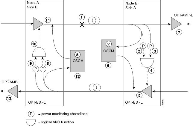
Two photodiodes at Node B monitor the received signal strength for the optical payload and OSC signals. When the fiber is cut, an LOS is detected at both of the photodiodes. The AND function then indicates an overall LOS condition, which causes the OPT-BST-L transmitter and OSCM lasers to shut down. This in turn leads to an LOS for both the optical payload and the OSC at Node A, which causes Node A to turn off the OSCM OSC transmitter and OPT-BST-L amplifier lasers. The sequence of events after a fiber cut is as follows (refer to the numbered circles in Figure 13-28):
2.![]() The Node B power monitoring photodiode detects an LOS-P on the OPT-BST-L card. For more information on alarms, refer to the Cisco ONS 15454 DWDM Troubleshooting Guide .
The Node B power monitoring photodiode detects an LOS-P on the OPT-BST-L card. For more information on alarms, refer to the Cisco ONS 15454 DWDM Troubleshooting Guide .
3.![]() On the OPT-BST-L card, the simultaneous LOS-O and LOS-P detection triggers a command to shut down the amplifier. CTC reports an LOS alarm (loss of continuity), while LOS-O and LOS-P are demoted. For more information on alarms, refer to the Cisco ONS 15454 DWDM Troubleshooting Guide .
On the OPT-BST-L card, the simultaneous LOS-O and LOS-P detection triggers a command to shut down the amplifier. CTC reports an LOS alarm (loss of continuity), while LOS-O and LOS-P are demoted. For more information on alarms, refer to the Cisco ONS 15454 DWDM Troubleshooting Guide .
4.![]() The OPT-BST-L card amplifier is shut down within one second.
The OPT-BST-L card amplifier is shut down within one second.
5.![]() The OSCM laser is shut down.
The OSCM laser is shut down.
6.![]() The OPT-AMP-L, OPT-AMP-C, or OPT-AMP-17-C card automatically shuts down due to a loss of incoming optical power.
The OPT-AMP-L, OPT-AMP-C, or OPT-AMP-17-C card automatically shuts down due to a loss of incoming optical power.
7.![]() The Node A power monitoring photodiode detects an LOS-O on the OPT-BST-L card and the OSCM card detects an LOS (OC3) at the SONET layer. For more information on alarms, refer to the Cisco ONS 15454 DWDM Troubleshooting Guide .
The Node A power monitoring photodiode detects an LOS-O on the OPT-BST-L card and the OSCM card detects an LOS (OC3) at the SONET layer. For more information on alarms, refer to the Cisco ONS 15454 DWDM Troubleshooting Guide .
8.![]() The Node A power monitoring photodiode detects an LOS-P on the OPT-BST-L card. For more information on alarms, refer to the Cisco ONS 15454 DWDM Troubleshooting Guide .
The Node A power monitoring photodiode detects an LOS-P on the OPT-BST-L card. For more information on alarms, refer to the Cisco ONS 15454 DWDM Troubleshooting Guide .
9.![]() On the OPT-BST-L, the simultaneous LOS-O and LOS-P detection triggers a command to shut down the amplifier. CTC reports an LOS alarm (loss of continuity), while the LOS-O and LOS-P are demoted. For more information on alarms, refer to the Cisco ONS 15454 DWDM Troubleshooting Guide .
On the OPT-BST-L, the simultaneous LOS-O and LOS-P detection triggers a command to shut down the amplifier. CTC reports an LOS alarm (loss of continuity), while the LOS-O and LOS-P are demoted. For more information on alarms, refer to the Cisco ONS 15454 DWDM Troubleshooting Guide .
10.![]() The OPT-BST-L card amplifier is shut down within one second.
The OPT-BST-L card amplifier is shut down within one second.
11.![]() The OSCM laser is shut down.
The OSCM laser is shut down.
12.![]() The Node A OPT-AMP-L, OPT-AMP-C, or OPT-AMP-17-C card automatically shuts down due to an LOS for the incoming optical power.
The Node A OPT-AMP-L, OPT-AMP-C, or OPT-AMP-17-C card automatically shuts down due to an LOS for the incoming optical power.
When the fiber is repaired, either an automatic or manual restart at the Node A OPT-BST-L transmitter or at the Node B OPT-BST-L transmitter is required. A system that has been shut down is reactivated through the use of a restart pulse. The pulse indicates the optical path is restored and transmission can begin. For example, when the far end, Node B, receives a pulse, it signals to the Node B OPT-BST-L transmitter to begin transmitting an optical signal. The OPT-BST-L receiver at Node A receives that signal and signals the Node A OPT-BST-L transmitter to resume transmitting.
Note![]() During a laser restart pulse, APR ensures that the laser power does not exceed Class 1 limits. See the “Automatic Power Reduction” section for more information about APR.
During a laser restart pulse, APR ensures that the laser power does not exceed Class 1 limits. See the “Automatic Power Reduction” section for more information about APR.
13.11.4.4 Scenario 4: Fiber Cut in Nodes Using OPT-AMP-L, OPT-AMP-C, OPT-AMP-17-C (OPT-LINE Mode), 40-SMR1-C, or 40-SMR2-C Cards
Figure 13-29 shows nodes using OPT-AMP-L, OPT-AMP-C, OPT-AMP-17-C (in OPT-LINE mode), 40-SMR1-C, or 40-SMR2-C cards with a fiber cut between them.
Note![]() A generic reference to the OPT-AMP card refers to the OPT-AMP-L, OPT-AMP-17-C, OPT-AMP-C, 40-SMR1-C, or 40-SMR2-C cards.
A generic reference to the OPT-AMP card refers to the OPT-AMP-L, OPT-AMP-17-C, OPT-AMP-C, 40-SMR1-C, or 40-SMR2-C cards.
Figure 13-29 Nodes Using OPT-AMP Cards
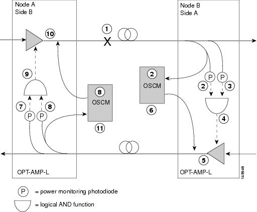
Two photodiodes at Node B monitor the received signal strength for the optical payload and OSC signals. When the fiber is cut, an LOS is detected at both of the photodiodes. The AND function then indicates an overall LOS condition, which causes the OPT-AMP card amplifier transmitter and OSCM card OSC lasers to shut down. This in turn leads to an LOS for both the optical payload and OSC at Node A, which causes Node A to turn off the OSCM card OSC and OPT-AMP card amplifier lasers. The sequence of events after a fiber cut is as follows (refer to the numbered circles in Figure 13-29):
2.![]() The Node B power monitoring photodiode detects an LOS-P on the OPT-AMP card. For more information on alarms, refer to the Cisco ONS 15454 DWDM Troubleshooting Guide .
The Node B power monitoring photodiode detects an LOS-P on the OPT-AMP card. For more information on alarms, refer to the Cisco ONS 15454 DWDM Troubleshooting Guide .
3.![]() On the OPT-AMP card, the simultaneous LOS-O and LOS-P detection triggers a command to shut down the amplifier. CTC reports an LOS alarm (loss of continuity), while LOS-O and LOS-P are demoted. For more information on alarms, refer to the Cisco ONS 15454 DWDM Troubleshooting Guide .
On the OPT-AMP card, the simultaneous LOS-O and LOS-P detection triggers a command to shut down the amplifier. CTC reports an LOS alarm (loss of continuity), while LOS-O and LOS-P are demoted. For more information on alarms, refer to the Cisco ONS 15454 DWDM Troubleshooting Guide .
4.![]() The OPT-AMP card amplifier is shut down within one second.
The OPT-AMP card amplifier is shut down within one second.
5.![]() The OSCM card laser is shut down.
The OSCM card laser is shut down.
6.![]() The Node A power monitoring photodiode detects an LOS-O on the OPT-AMP card and the OSCM card detects an LOS (OC3) at the SONET layer. For more information on alarms, refer to the Cisco ONS 15454 DWDM Troubleshooting Guide .
The Node A power monitoring photodiode detects an LOS-O on the OPT-AMP card and the OSCM card detects an LOS (OC3) at the SONET layer. For more information on alarms, refer to the Cisco ONS 15454 DWDM Troubleshooting Guide .
7.![]() The Node A power monitoring photodiode detects an LOS-P on the OPT-AMP card. For more information on alarms, refer to the Cisco ONS 15454 DWDM Troubleshooting Guide .
The Node A power monitoring photodiode detects an LOS-P on the OPT-AMP card. For more information on alarms, refer to the Cisco ONS 15454 DWDM Troubleshooting Guide .
8.![]() On the OPT-AMP card, the simultaneous LOS-O and LOS-P detection triggers a command to shut down the amplifier. CTC reports an LOS alarm (loss of continuity), while LOS-O and LOS-P are demoted. For more information on alarms, refer to the Cisco ONS 15454 DWDM Troubleshooting Guide .
On the OPT-AMP card, the simultaneous LOS-O and LOS-P detection triggers a command to shut down the amplifier. CTC reports an LOS alarm (loss of continuity), while LOS-O and LOS-P are demoted. For more information on alarms, refer to the Cisco ONS 15454 DWDM Troubleshooting Guide .
9.![]() The OPT-AMP card amplifier is shut down within one second.
The OPT-AMP card amplifier is shut down within one second.
10.![]() The OSCM card laser is shut down.
The OSCM card laser is shut down.
When the fiber is repaired, either an automatic or manual restart at the Node A OPT-AMP card transmitter or at the Node B OPT-AMP card transmitter is required. A system that has been shut down is reactivated through the use of a restart pulse. The pulse indicates that the optical path is restored and transmission can begin. For example, when the far end, Node B, receives a pulse, it signals to the Node B OPT-AMP card transmitter to begin transmitting an optical signal. The OPT-AMP card receiver at Node A receives that signal and signals the Node A OPT-AMP card transmitter to resume transmitting.
Note![]() During a laser restart pulse, APR ensures that the laser power does not exceed Class 1 limits. See the “Automatic Power Reduction” section for more information about APR.
During a laser restart pulse, APR ensures that the laser power does not exceed Class 1 limits. See the “Automatic Power Reduction” section for more information about APR.
13.11.4.5 Scenario 5: Fiber Cut in Nodes Using DCN Extension
Figure 13-30 shows a fiber cut scenario for nodes that do not have OSC connectivity. In the scenario, references to the OPT-BST cards refers to the OPT-BST, OPT-BST-L, OPT-BST-E, OPT-AMP-L, OPT-AMP-C, OPT-AMP-17-C, 40-SMR1-C, and 40-SMR2-C cards when provisioned in OPT-LINE mode.
Figure 13-30 Fiber Cut With DCN Extension
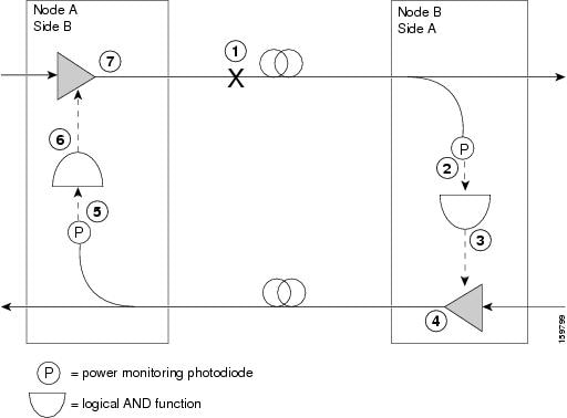
Two photodiodes at Node B monitor the received signal strength for the optical payload. When the fiber is cut, an LOS is detected on the channel photodiode while the other one never gets a signal because the OSC is not present. The AND function then indicates an overall LOS condition, which causes the OPT-BST amplifier transmitter to shut down. This in turn leads to a LOS for the optical payload at
Node A, which causes Node A to turn off the OPT-BST amplifier lasers.
The sequence of events after a fiber cut is as follows (refer to the numbered circles in Figure 13-30):
2.![]() The Node B power monitoring photodiode detects an LOS on the OPT-BST card. Refer to the Cisco ONS 15454 DWDM Troubleshooting Guide for LOS troubleshooting procedures.
The Node B power monitoring photodiode detects an LOS on the OPT-BST card. Refer to the Cisco ONS 15454 DWDM Troubleshooting Guide for LOS troubleshooting procedures.
3.![]() On the OPT-BST card, the LOS detection triggers a command to shut down the amplifier. Refer to the Cisco ONS 15454 DWDM Troubleshooting Guide for alarm troubleshooting procedures.
On the OPT-BST card, the LOS detection triggers a command to shut down the amplifier. Refer to the Cisco ONS 15454 DWDM Troubleshooting Guide for alarm troubleshooting procedures.
4.![]() The OPT-BST card amplifier is shut down within one second.
The OPT-BST card amplifier is shut down within one second.
5.![]() The Node A power monitoring photodiode detects a LOS on the OPT-BST card. Refer to the Cisco ONS 15454 DWDM Troubleshooting Guide for alarm troubleshooting procedures.
The Node A power monitoring photodiode detects a LOS on the OPT-BST card. Refer to the Cisco ONS 15454 DWDM Troubleshooting Guide for alarm troubleshooting procedures.
6.![]() On the OPT-BST, the LOS detection triggers a command to shut down the amplifier. Refer to the Cisco ONS 15454 DWDM Troubleshooting Guide .
On the OPT-BST, the LOS detection triggers a command to shut down the amplifier. Refer to the Cisco ONS 15454 DWDM Troubleshooting Guide .
7.![]() The OPT-BST card amplifier is shut down within one second.
The OPT-BST card amplifier is shut down within one second.
When the fiber is repaired, a manual restart with 9 sec restart pulse time (MANUAL RESTART) is required at the Node A OPT-BST transmitter and at the Node B OPT-BST transmitter. A system that has been shut down is reactivated through the use of a 9 sec restart pulse. The pulse indicates that the optical path is restored and transmission can begin.
For example, when the far end, Node B, receives a pulse, it signals to the Node B OPT-BST transmitter to begin transmitting an optical signal. The OPT-BST receiver at Node A receives that signal and signals the Node A OPT-BST transmitter to resume transmitting.
Note![]() During a laser restart pulse, APR ensures that the laser power does not exceed Class 1 limits. See the “Automatic Power Reduction” section for more information about APR.
During a laser restart pulse, APR ensures that the laser power does not exceed Class 1 limits. See the “Automatic Power Reduction” section for more information about APR.
13.11.4.6 Scenario 6: Fiber Cut in Nodes Using OPT-RAMP-C or OPT-RAMP-CE Cards
Figure 13-31 shows a fiber cut scenario for nodes using OPT-RAMP-C or OPT-RAMP-CE cards.
Figure 13-31 Nodes Using OPT-RAMP-C or OPT-RAMP-CE Cards
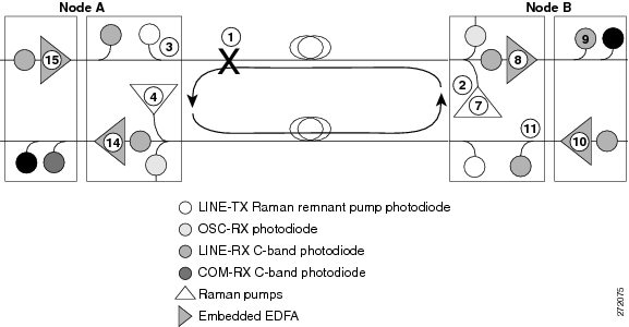
The sequence of events after a fiber cut is as follows (refer to the numbered circles in Figure 13-31):
1.![]() Fiber is cut in the direction of Node A to Node B.
Fiber is cut in the direction of Node A to Node B.
2.![]() No alarms are initially detected on Node B. The Raman pumps are still in ON state and continue to pump power on to the broken fiber. The residual Raman noise propagated towards the LINE-RX port keeps the embedded EDFA active. The LOS alarm is not raised on the DC-TX port because the EDFA continues to transmit minimum output power to the line amplifier that it is connected to.
No alarms are initially detected on Node B. The Raman pumps are still in ON state and continue to pump power on to the broken fiber. The residual Raman noise propagated towards the LINE-RX port keeps the embedded EDFA active. The LOS alarm is not raised on the DC-TX port because the EDFA continues to transmit minimum output power to the line amplifier that it is connected to.
3.![]() On Node A, the OPT-RAMP-C card no longer receives the Raman remnant pump signal on the LINE-TX port. The RAMAN-RX port detects an LOS-R alarm on the OPT-RAMP-C or OPT-RAMP-CE card. The OSCM card that is connected to the OPT-RAMP-C card detects OSC failure and raises a LOS alarm at the OC-3 level. For the LOS-R troubleshooting procedures, see the Cisco ONS 15454 DWDM Troubleshooting Guide.
On Node A, the OPT-RAMP-C card no longer receives the Raman remnant pump signal on the LINE-TX port. The RAMAN-RX port detects an LOS-R alarm on the OPT-RAMP-C or OPT-RAMP-CE card. The OSCM card that is connected to the OPT-RAMP-C card detects OSC failure and raises a LOS alarm at the OC-3 level. For the LOS-R troubleshooting procedures, see the Cisco ONS 15454 DWDM Troubleshooting Guide.
4.![]() On the OPT-RAMP-C or OPT-RAMP-CE card, the LOS-R alarm triggers a command to shut down the Raman pump on Node A.
On the OPT-RAMP-C or OPT-RAMP-CE card, the LOS-R alarm triggers a command to shut down the Raman pump on Node A.
5.![]() On Node A, the LOS alarm on the OSCM card causes a laser TX shutdown because ALS is always enabled on the OSCM card. This results in the OPT-RAMP-C or OPT-RAMP-CE card raising the LOS-O alarm on the OSC-RX port.
On Node A, the LOS alarm on the OSCM card causes a laser TX shutdown because ALS is always enabled on the OSCM card. This results in the OPT-RAMP-C or OPT-RAMP-CE card raising the LOS-O alarm on the OSC-RX port.
6.![]() Because the Raman pump on Node A is shutdown, the RAMAN-RX port detects an LOS-R alarm on Node B.
Because the Raman pump on Node A is shutdown, the RAMAN-RX port detects an LOS-R alarm on Node B.
7.![]() The LOS-R alarm triggers a command to shut down the Raman pump on Node B.
The LOS-R alarm triggers a command to shut down the Raman pump on Node B.
8.![]() The embedded EDFA on Node B no longer receives residual power Raman noise. An LOS alarm is detected on the input port of the EDFA that causes the embedded EDFA to shut down.
The embedded EDFA on Node B no longer receives residual power Raman noise. An LOS alarm is detected on the input port of the EDFA that causes the embedded EDFA to shut down.
9.![]() The LINE-RX port of the line amplifier on Node B that receives the payload signal from the embedded EDFA of the OPT-RAMP-C card detects an LOS alarm.
The LINE-RX port of the line amplifier on Node B that receives the payload signal from the embedded EDFA of the OPT-RAMP-C card detects an LOS alarm.
10.![]() The LOS alarm triggers an ALS and causes the line amplifier to shut down.
The LOS alarm triggers an ALS and causes the line amplifier to shut down.
11.![]() The COM-RX port of the OPT-RAMP-C card on Node B and consequently the LINE-TX port that is connected to Node A through the safe fiber, no longer receive power.
The COM-RX port of the OPT-RAMP-C card on Node B and consequently the LINE-TX port that is connected to Node A through the safe fiber, no longer receive power.
12.![]() Because the OSCM card on Node A is in the ALS condition, there is no OSC signal on the LINE-TX port of the OSCM card on Node B that raises an LOS alarm.
Because the OSCM card on Node A is in the ALS condition, there is no OSC signal on the LINE-TX port of the OSCM card on Node B that raises an LOS alarm.
13.![]() The LOS alarm on the OSCM card causes a laser TX shutdown that raises an LOS-O alarm on the OSC-RX port of the OPT-RAMP-C card on Node B. The simultaneous presence of an LOS-O alarm on the OSC-RX port and an LOS-R alarm on the RAMAN-RX port of the OPT-RAMP-C card can be interpreted as a fiber cut and an LOS alarm is generated on the LINE-RX port.
The LOS alarm on the OSCM card causes a laser TX shutdown that raises an LOS-O alarm on the OSC-RX port of the OPT-RAMP-C card on Node B. The simultaneous presence of an LOS-O alarm on the OSC-RX port and an LOS-R alarm on the RAMAN-RX port of the OPT-RAMP-C card can be interpreted as a fiber cut and an LOS alarm is generated on the LINE-RX port.
14.![]() On Node A, the LINE-RX port of the OPT-RAMP-C card detects an LOS alarm because the C-band payload is absent and triggers a command to shut down the embedded EDFA.
On Node A, the LINE-RX port of the OPT-RAMP-C card detects an LOS alarm because the C-band payload is absent and triggers a command to shut down the embedded EDFA.
15.![]() The line amplifier that receives the payload signal from the embedded EDFA of the OPT-RAMP-C card detects an LOS alarm on its LINE-RX port and causes the line amplifier to shut down. The C-band power is no longer transmitted to the COM-RX port of the OPT-RAMP-C card and subsequently to the LINE-TX port that connected to the broken fiber.
The line amplifier that receives the payload signal from the embedded EDFA of the OPT-RAMP-C card detects an LOS alarm on its LINE-RX port and causes the line amplifier to shut down. The C-band power is no longer transmitted to the COM-RX port of the OPT-RAMP-C card and subsequently to the LINE-TX port that connected to the broken fiber.
An Automatic Laser Restart (ALR) on the Raman pump is detected when the fiber is restored. This turns both the Raman pumps to ON state, on both the nodes. When the power on the Raman pump is restored, it turns on the embedded EDFA also. The booster amplifiers on both Node A and Node B detect power on the LINE-RX port. This restarts the booster amplifier.
Once the active TCC of the Raman node detects a stable condition, the link is automatically revaluated. The TCC initiates a fiber restoration procedure as described in Fiber Cut Recovery in Nodes Using OPT-RAMP-C or OPT-RAMP-CE Cards. The procedure takes a maximum of one or two minutes and causes a temporary transient condition on C-band signals.
13.11.4.7 Scenario 7: Fiber Cut in Optical Line Amplifier Nodes Using OPT-RAMP-C or OPT-RAMP-CE Cards
In the following sections, fiber cut scenarios for three node layouts are given:
13.11.4.7.1 Scenario 7A—Node Equipped With OPT-RAMP-C or OPT-RAMP-CE Cards on Side A and Side B.
Figure 13-32 shows a fiber cut scenario for a node equipped with OPT-RAMP-C or OPT-RAMP-CE cards on Side A and Side B.
Figure 13-32 Nodes Using OPT-RAMP-C or OPT-RAMP-CE Cards on Side A and B
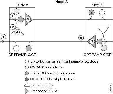
The sequence of events after a fiber cut is as follows (refer to the numbered circles in Figure 13-32):
1.![]() The fiber that is connected to the LINE-TX port of the OPT-RAMP-C or OPT-RAMP-CE card on Side A of Node A is cut. The Raman link goes down.
The fiber that is connected to the LINE-TX port of the OPT-RAMP-C or OPT-RAMP-CE card on Side A of Node A is cut. The Raman link goes down.
2.![]() The RAMAN-RX port detects an LOS-R alarm on the OPT-RAMP-C or OPT-RAMP-CE card on Side A. For LOS-R troubleshooting procedures, see the Cisco ONS 15454 DWDM Troubleshooting Guide.
The RAMAN-RX port detects an LOS-R alarm on the OPT-RAMP-C or OPT-RAMP-CE card on Side A. For LOS-R troubleshooting procedures, see the Cisco ONS 15454 DWDM Troubleshooting Guide.
3.![]() On the OPT-RAMP-C or OPT-RAMP-CE card, the LOS-R alarm triggers a command to shut down the Raman pump on Side A.
On the OPT-RAMP-C or OPT-RAMP-CE card, the LOS-R alarm triggers a command to shut down the Raman pump on Side A.
4.![]() No power is detected by the embedded EDFA on the LINE-RX port of the OPT-RAMP-C or OPT-RAMP-CE card on Side A.
No power is detected by the embedded EDFA on the LINE-RX port of the OPT-RAMP-C or OPT-RAMP-CE card on Side A.
5.![]() The embedded EDFA of the OPT-RAMP-C or OPT-RAMP-CE card on Side A is automatically shutdown.
The embedded EDFA of the OPT-RAMP-C or OPT-RAMP-CE card on Side A is automatically shutdown.
6.![]() An LOS-P alarm is detected on the COM-RX port of the OPT-RAMP-C or OPT-RAMP-CE card on Side B of Node A.
An LOS-P alarm is detected on the COM-RX port of the OPT-RAMP-C or OPT-RAMP-CE card on Side B of Node A.
7.![]() The LOS-P alarm triggers an ALS of the embedded EDFA of the OPT-RAMP-C or OPT-RAMP-CE card on Side B.
The LOS-P alarm triggers an ALS of the embedded EDFA of the OPT-RAMP-C or OPT-RAMP-CE card on Side B.
8.![]() No C-band power is transmitted out of the COM-TX port of the OPT-RAMP-C or OPT-RAMP-CE card on Side B, to the COM-RX port and subsequently to the LINE-TX port of the OPT-RAMP-C or OPT-RAMP-CE card on Side A that is connected to the broken fiber.
No C-band power is transmitted out of the COM-TX port of the OPT-RAMP-C or OPT-RAMP-CE card on Side B, to the COM-RX port and subsequently to the LINE-TX port of the OPT-RAMP-C or OPT-RAMP-CE card on Side A that is connected to the broken fiber.
For information about fiber cut recovery, see the “Fiber Cut Recovery in Nodes Using OPT-RAMP-C or OPT-RAMP-CE Cards” section.
13.11.4.7.2 Scenario 7B—Node Equipped With OPT-RAMP-C or OPT-RAMP-CE and Booster Cards on Side A and OPT-RAMP-C or OPT-RAMP-CE Cards on Side B.
Scenario 1—Fiber cut on the LINE-TX port of the OPT-RAMP-C or OPT-RAMP-CE card on Side A (Figure 13-33).
Figure 13-33 Nodes Using OPT-RAMP-C or OPT-RAMP-CE and Booster Cards on Side A and OPT-RAMP-CE Cards on Side B - Scenario 1
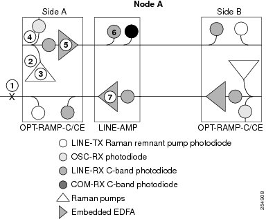
The sequence of events after a fiber cut is as follows (refer to the numbered circles in Figure 13-33):
1.![]() The fiber that is connected to the LINE-TX port of the OPT-RAMP-C or OPT-RAMP-CE card on Side A of Node A is cut.The Raman link goes down.
The fiber that is connected to the LINE-TX port of the OPT-RAMP-C or OPT-RAMP-CE card on Side A of Node A is cut.The Raman link goes down.
2.![]() The RAMAN-RX port detects an LOS-R alarm on the OPT-RAMP-C or OPT-RAMP-CE card. For LOS-R troubleshooting procedures, see the Cisco ONS 15454 DWDM Troubleshooting Guide.
The RAMAN-RX port detects an LOS-R alarm on the OPT-RAMP-C or OPT-RAMP-CE card. For LOS-R troubleshooting procedures, see the Cisco ONS 15454 DWDM Troubleshooting Guide.
3.![]() On the OPT-RAMP-C or OPT-RAMP-CE card, the LOS-R alarm triggers a command to shut down the Raman pump on Side A.
On the OPT-RAMP-C or OPT-RAMP-CE card, the LOS-R alarm triggers a command to shut down the Raman pump on Side A.
4.![]() No power is detected by the embedded EDFA on the LINE-RX port of the OPT-RAMP-C or OPT-RAMP-CE card on Side A.
No power is detected by the embedded EDFA on the LINE-RX port of the OPT-RAMP-C or OPT-RAMP-CE card on Side A.
5.![]() The embedded EDFA of the OPT-RAMP-C or OPT-RAMP-CE card on Side A is automatically shutdown.
The embedded EDFA of the OPT-RAMP-C or OPT-RAMP-CE card on Side A is automatically shutdown.
6.![]() An LOS alarm is detected on the downstream line amplifier on Side A of Node A since it no longer receives the optical payload from the embedded EDFA of the OPT-RAMP-C or OPT-RAMP-CE card.
An LOS alarm is detected on the downstream line amplifier on Side A of Node A since it no longer receives the optical payload from the embedded EDFA of the OPT-RAMP-C or OPT-RAMP-CE card.
7.![]() The ALS mechanism causes the line amplifier to shut down.
The ALS mechanism causes the line amplifier to shut down.
8.![]() The C-band power is no longer transmitted out of the line amplifier to the COM-RX port and subsequently to the LINE-TX port of the OPT-RAMP-C or OPT-RAMP-CE card that is connected to the broken fiber.
The C-band power is no longer transmitted out of the line amplifier to the COM-RX port and subsequently to the LINE-TX port of the OPT-RAMP-C or OPT-RAMP-CE card that is connected to the broken fiber.
For information about fiber cut recovery, see the “Fiber Cut Recovery in Nodes Using OPT-RAMP-C or OPT-RAMP-CE Cards” section.
Scenario 2—Fiber cut on the LINE-TX port of the OPT-RAMP-C or OPT-RAMP-CE card on Side B (Figure 13-34).
Figure 13-34 Nodes Using OPT-RAMP-C or OPT-RAMP-CE and Booster Cards on Side A and OPT-RAMP-CE Cards on Side B - Scenario 2
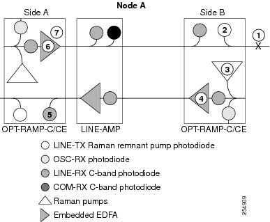
The sequence of events after a fiber cut is as follows (refer to the numbered circles in Figure 13-34):
1.![]() The fiber that is connected to the LINE-TX port of the OPT-RAMP-C or OPT-RAMP-CE card on Side B of Node A is cut.
The fiber that is connected to the LINE-TX port of the OPT-RAMP-C or OPT-RAMP-CE card on Side B of Node A is cut.
2.![]() An LOS-R alarm is detected on the OPT-RAMP-C or OPT-RAMP-CE card on Side B because it no longer receives the Raman remnant signal from Node B.
An LOS-R alarm is detected on the OPT-RAMP-C or OPT-RAMP-CE card on Side B because it no longer receives the Raman remnant signal from Node B.
3.![]() On the OPT-RAMP-C or OPT-RAMP-CE card, the LOS-R alarm triggers a command to shut down the Raman pump on Side B.
On the OPT-RAMP-C or OPT-RAMP-CE card, the LOS-R alarm triggers a command to shut down the Raman pump on Side B.
4.![]() The embedded EDFA of the OPT-RAMP-C or OPT-RAMP-CE card on Side B no longer receives residual Raman power and causes it to shut down.
The embedded EDFA of the OPT-RAMP-C or OPT-RAMP-CE card on Side B no longer receives residual Raman power and causes it to shut down.
5.![]() A very low C-band signal reaches the OPT-RAMP-C or OPT-RAMP-CE card on Side A. An LOS-P alarm is detected on the COM-RX port of the OPT-RAMP-C or OPT-RAMP-CE card on Side A.
A very low C-band signal reaches the OPT-RAMP-C or OPT-RAMP-CE card on Side A. An LOS-P alarm is detected on the COM-RX port of the OPT-RAMP-C or OPT-RAMP-CE card on Side A.
6.![]() The embedded EDFA of the OPT-RAMP-C or OPT-RAMP-CE card on Side A is automatically shutdown.
The embedded EDFA of the OPT-RAMP-C or OPT-RAMP-CE card on Side A is automatically shutdown.
7.![]() The C-band power is no longer transmitted to the line amplifier through the DC-TX port of the OPT-RAMP-C or OPT-RAMP-CE card on Side A, to the COM-RX port and subsequently to the LINE-TX port of the OPT-RAMP-C or OPT-RAMP-CE card on Side B that is connected to the broken fiber.
The C-band power is no longer transmitted to the line amplifier through the DC-TX port of the OPT-RAMP-C or OPT-RAMP-CE card on Side A, to the COM-RX port and subsequently to the LINE-TX port of the OPT-RAMP-C or OPT-RAMP-CE card on Side B that is connected to the broken fiber.
For information about fiber cut recovery, see the “Fiber Cut Recovery in Nodes Using OPT-RAMP-C or OPT-RAMP-CE Cards” section.
13.11.4.7.3 Scenario 7C—Node Equipped With OPT-RAMP-C or OPT-RAMP-CE and Booster Cards on Side A and OSC-CSM Cards on Side B.
Scenario 1—Fiber cut on the LINE-TX port of the OPT-RAMP-C or OPT-RAMP-CE card on Side A (Figure 13-35).
Figure 13-35 Nodes Using OPT-RAMP-C or OPT-RAMP-CE and Booster Cards on Side A and OSC-CSM Cards on Side B - Scenario 1
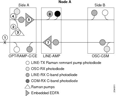
The sequence of events after a fiber cut is as follows (refer to the numbered circles in Figure 13-35):
1.![]() The fiber that is connected to the LINE-TX port of the OPT-RAMP-C or OPT-RAMP-CE card on Side A of Node A is cut. The Raman link goes down.
The fiber that is connected to the LINE-TX port of the OPT-RAMP-C or OPT-RAMP-CE card on Side A of Node A is cut. The Raman link goes down.
2.![]() The RAMAN-RX port detects an LOS-R alarm on the OPT-RAMP-C or OPT-RAMP-CE card. For LOS-R troubleshooting procedures, see the Cisco ONS 15454 DWDM Troubleshooting Guide.
The RAMAN-RX port detects an LOS-R alarm on the OPT-RAMP-C or OPT-RAMP-CE card. For LOS-R troubleshooting procedures, see the Cisco ONS 15454 DWDM Troubleshooting Guide.
3.![]() On the OPT-RAMP-C or OPT-RAMP-CE card, the LOS-R alarm triggers a command to shut down the Raman pump on Side A.
On the OPT-RAMP-C or OPT-RAMP-CE card, the LOS-R alarm triggers a command to shut down the Raman pump on Side A.
4.![]() No power is detected by the embedded EDFA on the LINE-RX port of the OPT-RAMP-C or OPT-RAMP-CE card on Side A.
No power is detected by the embedded EDFA on the LINE-RX port of the OPT-RAMP-C or OPT-RAMP-CE card on Side A.
5.![]() The embedded EDFA of the OPT-RAMP-C or OPT-RAMP-CE card on Side A is automatically shutdown.
The embedded EDFA of the OPT-RAMP-C or OPT-RAMP-CE card on Side A is automatically shutdown.
6.![]() An LOS alarm is detected on the downstream line amplifier on Side A of Node A because it no longer receives the optical payload from the embedded EDFA of the OPT-RAMP-C or OPT-RAMP-CE card.
An LOS alarm is detected on the downstream line amplifier on Side A of Node A because it no longer receives the optical payload from the embedded EDFA of the OPT-RAMP-C or OPT-RAMP-CE card.
7.![]() The ALS mechanism causes the line amplifier to shut down.
The ALS mechanism causes the line amplifier to shut down.
8.![]() The C-band power is no longer transmitted out of the line amplifier to the COM-RX port and subsequently to the LINE-TX port of the OPT-RAMP-C or OPT-RAMP-CE card that is connected to the broken fiber on Side A.
The C-band power is no longer transmitted out of the line amplifier to the COM-RX port and subsequently to the LINE-TX port of the OPT-RAMP-C or OPT-RAMP-CE card that is connected to the broken fiber on Side A.
For information about fiber cut recovery, see the “Fiber Cut Recovery in Nodes Using OPT-RAMP-C or OPT-RAMP-CE Cards” section.
Scenario 2—Fiber cut on the LINE-RX port of the OSC-CSM card on Side B (Figure 13-36).
Figure 13-36 Nodes Using OPT-RAMP-C or OPT-RAMP-CE and Booster Cards on Side A and OSC-CSM Cards on Side B - Scenario 2
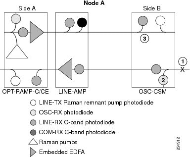
The sequence of events after a fiber cut is as follows (refer to the numbered circles in Figure 13-36):
1.![]() The fiber that is connected to the LINE-RX port of the OSC-CSM card on Side B of Node A is cut.
The fiber that is connected to the LINE-RX port of the OSC-CSM card on Side B of Node A is cut.
2.![]() An LOS alarm is detected on the OSC-CSM card on Side B because it no longer receives the OSC signal.
An LOS alarm is detected on the OSC-CSM card on Side B because it no longer receives the OSC signal.
3.![]() The power is shut down by means of a 1x1 optical switch in the OSC-CSM card.
The power is shut down by means of a 1x1 optical switch in the OSC-CSM card.
Note![]() During a laser restart pulse, APR ensures that the laser power does not exceed Class 1 limits. For more information about APR, see the “Automatic Power Reduction” section.
During a laser restart pulse, APR ensures that the laser power does not exceed Class 1 limits. For more information about APR, see the “Automatic Power Reduction” section.
13.11.4.8 Fiber Cut Recovery in Nodes Using OPT-RAMP-C or OPT-RAMP-CE Cards
A fiber cut recovery procedure is automatically performed after the OCH channels are restored to measure the actual Raman gain on the span.
1.![]() Node A sends a message through OSC or DCN to Node B to be ready for Raman Gain measurement.
Node A sends a message through OSC or DCN to Node B to be ready for Raman Gain measurement.
2.![]() The TCC configures the Raman pumps on Node A to operate at APR power (+8 dBm). In this state, no Raman amplification is generated on the input fiber of Node A and a reliable span loss measurement is performed. The Raman pumps must not be shut down completely to avoid an improper fiber cut event.
The TCC configures the Raman pumps on Node A to operate at APR power (+8 dBm). In this state, no Raman amplification is generated on the input fiber of Node A and a reliable span loss measurement is performed. The Raman pumps must not be shut down completely to avoid an improper fiber cut event.
3.![]() Node B acknowledges the message and reports the value of the Raman power received on the channel to Node A.
Node B acknowledges the message and reports the value of the Raman power received on the channel to Node A.
4.![]() On Node A, the TCC configures the line amplifiers in power control mode and APR state (+8 dBm). The C-band power received with Raman pumps in OFF state is recorded.
On Node A, the TCC configures the line amplifiers in power control mode and APR state (+8 dBm). The C-band power received with Raman pumps in OFF state is recorded.
5.![]() The TCC turns the Raman pumps to full power maintaining the Raman ratio calculated by the Raman installation wizard. The Raman total power is adjusted, so that the Raman gain setpoint is reached. The actual Raman gain is calculated using the C-band power values.
The TCC turns the Raman pumps to full power maintaining the Raman ratio calculated by the Raman installation wizard. The Raman total power is adjusted, so that the Raman gain setpoint is reached. The actual Raman gain is calculated using the C-band power values.
6.![]() When the Raman gain setpoint is reached, the value of the Power field gets updated and the status of the Fiber Cut Recovery field changes to “Executed” in CTC.
When the Raman gain setpoint is reached, the value of the Power field gets updated and the status of the Fiber Cut Recovery field changes to “Executed” in CTC.
If the provisioned Raman gain setpoint is not reached by setting the Raman total power to the maximum value of 450 mW, the procedure stops and the RAMAN-G-NOT-REACHED alarm is raised on the OPT-RAMP-C or OPT-RAMP-CE card.
13.11.5 Network Optical Safety on RAMAN-CTP and RAMAN-COP Cards
Bidirectional optical safety mechanisms for Raman and C-band signals have been independently implemented. The Raman pump laser shutdown and restart is managed by the RAMAN-CTP card. The RAMAN-COP card is controlled by the RAMAN-CTP card using two backplane wires. The RAMAN-COP card can be absent in some node configurations.
The C-band signal shutdown and restart is managed by an MSTP card, such as 40-SMR1-C, 40-SMR-2C, OPT-EDFA-17, or OPT-EDFA-24.
The optical safety mechanism on the RAMAN-CTP and RAMAN-COP cards is managed by:
- DFB signal (1568.77 nm) and detection of DFB related signals—The RAMAN-CTP card on the local node transmits a DFB signal and waits for a similar response from the remote side. If a valid DFB signal is not detected, the RAMAN-CTP card switches off its transmitting DFB laser that causes a loss of DFB signal on the remote RAMAN-CTP card which in turn switches off its DFB laser. Both the RAMAN-CTP cards must turn off the DFB signals, when a fiber cut occurs.
- Raman pump laser back reflection mechanism on the RAMAN-CTP and RAMAN-COP cards—This mechanism uses the ratio between the back-reflected optical power and the total output Raman pump power to reduce the output power when patchcords are removed. If excessive back-reflection occurs, a Raman Laser Shutdown (RLS) alarm is raised on the RAMAN port where the failure is detected.
- Photodiode (P8) on the RAMAN-CTP card—The photodiode (P8) detects the Raman pump power transmitted by the RAMAN-COP card and is used to check for optical continuity between the RAMAN-CTP and RAMAN-COP cards. The RAMAN-COP card is shut down if the cards get disconnected.
13.12 Network-Level Gain—Tilt Management of Optical Amplifiers
The ability to control and adjust per channel optical power equalization is a principal feature of ONS 15454 DWDM metro core network applications. A critical parameter to assure optical spectrum equalization throughout the DWDM system is the gain flatness of erbium-doped fiber amplifiers (EDFAs).
Two items, gain tilt and gain ripple, are factors in the power equalization of optical amplifier cards such as the OPT-BST and OPT-PRE. Figure 13-37 shows a graph of the amplifier output power spectrum and how it is affected by gain tilt and gain ripple.
Figure 13-37 Effect of Gain Ripple and Gain Tilt on Amplifier Output Power
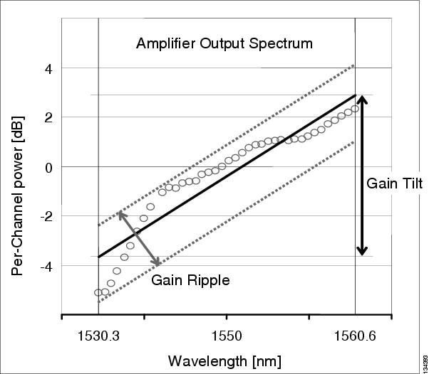
Gain ripple and gain tilt are defined as follows:
- Gain ripple is random and depends on the spectral shape of the amplifier optical components.
- Gain tilt is systematic and depends on the gain setpoint (Gstp) of the optical amplifier, which is a mathematical function F(Gstp) that relates to the internal amplifier design.
Gain tilt is the only contribution to the power spectrum disequalization that can be compensated at the card level. A VOA internal to the amplifier can be used to compensate for gain tilt.
An optical spectrum analyzer (OSA) is used to acquire the output power spectrum of an amplifier. The OSA shows the peak-to-peak difference between the maximum and minimum power levels, and takes into account the contributions of both gain tilt and gain ripple.
Note![]() Peak-to-peak power acquisition using an OSA cannot be used to measure the gain tilt, because gain ripple itself is a component of the actual measurement.
Peak-to-peak power acquisition using an OSA cannot be used to measure the gain tilt, because gain ripple itself is a component of the actual measurement.
13.12.1 Gain Tilt Control at the Card Level
The OPT-BST and OPT-PRE amplifier cards have a flat output (gain tilt = 0 dB) for only a specific gain value (Gdesign), based on the internal optical design (see Figure 13-38).
Figure 13-38 Flat Gain (Gain Tilt = 0 dB)
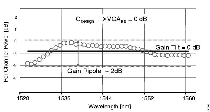
If the working gain setpoint of the amplifier is different from Gdesign, the output spectrum begins to suffer a gain tilt variation.
In order to compensate for the absolute value of the increase of the spectrum tilt, the OPT-BST and OPT-PRE cards automatically adjust the attenuation of the VOA to maintain a flat power profile at the output, as shown in Figure 13-39.
Figure 13-39 Effect of VOA Attenuation on Gain Tilt

The VOA attenuator automatic regulation guarantees (within limits) a zero tilt condition in the EDFA for a wide range of possible gain setpoint values.
Table 13-2 shows the flat output gain range limits for the OPT-BST and OPT-PRE cards, as well as the maximum (worst case) values of gain tilt and gain ripple expected in the specific gain range.
|
|
|
|
|
|---|---|---|---|
If the operating gain value is outside of the range shown in Table 13-2 , the EDFA introduces a tilt contribution for which the card itself cannot directly compensate. This condition is managed in different ways, depending the amplifier card type:
- OPT-BST—The OPT-BST amplifier is, by design, not allowed to work outside the zero tilt range. Cisco TransportPlanner network designs use the OPT-BST amplifier card only when the gain is less than or equal to 20 dB.
- OPT-PRE—Cisco TransportPlanner allows network designs even if the operating gain value is equal to or greater than 21 dB. In this case, a system-level tilt compensation strategy is adopted by the DWDM system. A more detailed explanation is given in System Level Gain Tilt Control.
13.12.2 System Level Gain Tilt Control
System level gain tilt control for OPT-PRE cards is achievable with two main scenarios:
13.12.2.1 System Gain Tilt Compensation Without ROADM Nodes
When an OPT-PRE card along a specific line direction (Side A-to-Side B or Side B-to-Side A) is working outside the flat output gain range (G > 21 dB), the unregulated tilt is compensated for in spans that are not connected to ROADM nodes by configuring an equal but opposite tilt on one or more of the amplifiers in the downstream direction. The number of downstream amplifiers involved depends on the amount of tilt compensation needed and the gain setpoint of the amplifiers that are involved. See Figure 13-40.
Figure 13-40 System Tilt Compensation Without an ROADM Node
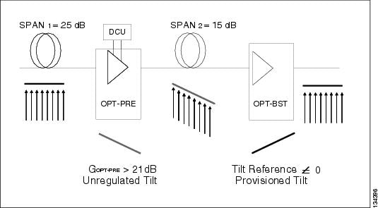
The proper Tilt Reference value is calculated by Cisco TransportPlanner and inserted in the Installation Parameter List imported during the node turn-up process (see Chapter 14, “Turn Up a Node”). For both OPT-PRE and OPT-BST cards, the provisionable Gain Tilt Reference range is between –3 dB and +3 dB.
During the ANS procedure, the Tilt value for the OPT-BST or OPT-PRE card is provisioned by the TCC2/TCC2P/TCC3/TNC/TNCE/TSC/TSCE card (see Figure 13-41). The provisioned Tilt Reference Value is reported in the CTC OPT-PRE or OPT-BST card view (in the Provisioning > Opt. Ampli. Line > Parameters > Tilt Reference tab).
Figure 13-41 Cisco TransportPlanner Installation Parameters
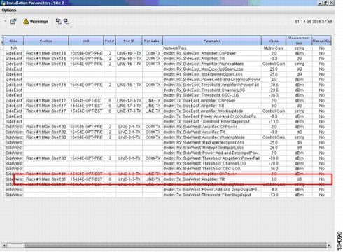
13.12.2.2 System Gain Tilt Compensation With ROADM Nodes
When a ROADM node is present in the network, as shown in Figure 13-42, a per channel dynamic gain equalization can be performed. Both gain tilt and gain ripple are completely compensated using the following techniques:
- Implementing the per channel VOAs present inside the 32WSS card
- Operating in Power Control Mode with the specific power setpoint designed by Cisco TransportPlanner
Figure 13-42 System Tilt Compensation With an ROADM Node
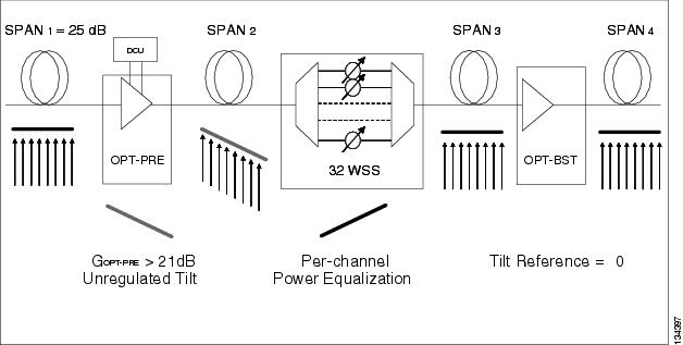
13.13 Optical Data Rate Derivations
This section discusses the derivation of several data rates commonly used in optical networking.
13.13.1 OC-192/STM-64 Data Rate (9.95328 Gbps)
The SONET OC-1 rate is 51.84 Mbps. This rate results from a standard SONET frame, which consists of 9 rows of 90 columns of 8-bit bytes (810 bytes total). The transmission rate is 8000 frames per second (125 microseconds per frame). This works out to 51.84 Mbps, as follows:
(9) x (90 bytes/frame) x (8 bits/byte) x (8000 frames/sec) = 51.84 Mbps
OC-192 is 192 x 51.84 Mbps = 9953.28 Mbps = 9.95328 Gbps
STM-64 is an SDH rate that is equivalent to the SONET OC-192 data rate.
13.13.2 10GE Data Rate (10.3125 Gbps)
10.3125 Gbps is the standard 10 Gbps Ethernet LAN rate. The reason the rate is higher than 10.000 Gbps is due to the 64-bit to 66-bit data encoding. The result is 10 Gbps x 66/64 = 10.3125 Gbps. The reason for 64-bit to 66-bit encoding is to ensure that there are adequate data transitions to ensure proper operation of a clock and data recovery circuit at the far end. Additionally, the encoding assures a data stream that is DC balanced.
13.13.3 10G FC Data Rate (10.51875 Gbps)
The Fibre Channel rate is based on the OC-192 rate of 9.95328 Gbps, with the addition of 64-bit to 66-bit encoding and WAN Interconnect Sublayer (WIS) overhead bytes.
The rate is derived from the basic 9.95328 Gbps OC-192 rate. First, it has the 64-bit to 66-bit encoding added, which brings it to the 10.3125 Gbps rate (10 Gbps x 66/64 = 10.3125 Gbps). Beyond that, the WIS overhead is added, which is an additional two percent on top of the 10.3125 Gbps. This yields:
13.13.4 ITU-T G.709 Optical Data Rates
To understand optical networking data rates, an understanding of the ITU-T G.709 frame structure, shown in Figure 13-43, is needed.
Figure 13-43 ITU-T G.709 Frame Structure
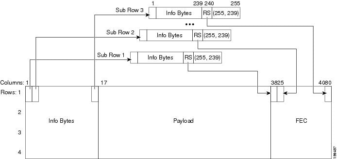
Each of the sub-rows in Figure 13-43 contains 255 bytes. Sixteen are interleaved horizontally (16 x 255 = 4080). This is repeated four times to make up the complete ITU-T G.709 frame.
The Reed Solomon (RS) (255,239) designation indicates the forward error correction (FEC) bytes. There are 16 FEC, or parity, bytes. The ITU-T G.709 protocol uses one overhead byte and 238 data bytes to compute 16 parity bytes to form 255 byte blocks—the RS (255,239) algorithm. Interleaving the information provides two key advantages. First, the encoding rate of each stream is reduced relative to the line transmission rate and, second, it reduces the sensitivity to bursts of error. The interleaving combined with the inherent correction strength of the RS (255,239) algorithm enables the correction of transmission bursts of up to 128 consecutive errored bytes. As a result, the ITU-T G.709 contiguous burst error correcting capability is enhanced 16 times above the capacity of the RS(255,239) algorithm by itself.
ITU-T G.709 defines the Optical Transport Unit 2 (OTU2) rate as 10.70923 Gbps. ITU-T G.709 defines three line rates:
1.![]() 2,666,057.143 kbps—Optical Transport Unit 1 (OTU1)
2,666,057.143 kbps—Optical Transport Unit 1 (OTU1)
2.![]() 10,709,225.316 kbps—Optical Transport Unit 2 (OTU2)
10,709,225.316 kbps—Optical Transport Unit 2 (OTU2)
3.![]() 43,018,413.559 kbps—Optical Transport Unit 3 (OTU3)
43,018,413.559 kbps—Optical Transport Unit 3 (OTU3)
The OTU2 rate is higher than OC-192 because the OTU2 has to carry overhead and FEC bytes in its frame; the bits must be sent faster to carry the payload information at the OC-192 rate.
The ITU-T G.709 frame has two parts. Two are similar to a SDH/SONET frame:
1.![]() Overhead area for operation, administration, and maintenance functions
Overhead area for operation, administration, and maintenance functions
13.13.4.1 OC-192 Packaged Into OTU2 G.709 Frame Data Rate (10.70923 Gbps)
In this case, an OC-192 frame is being transported over a OTU2 G.709 frame, which adds the benefit of FEC. The OC-192 data rate (9.95328 Gbps) must increase in order to transport more bytes (OC-192 plus ITU-T G.709 overhead plus ITU-T G.709 FEC bytes) in the same amount of time. In an OTU2 transmission, 237 of the 255 bytes are OC-192 payload. This means the resultant data rate is:
13.13.4.2 10GE Packaged Into OTU2 G.709 Frame Data Rate (Nonstandard 11.0957 Gbps)
Encapsulating Ethernet data into an OTU2 G.709 frame is considered nonstandard. The goal is to add the benefit of ITU-T G.709 encapsulation to achieve better burst error performance. However, this means adding overhead and FEC bytes, so more bytes must be transmitted in the same amount of time, so the data rate must increase. The new date rate is:
13.13.4.3 10G FC Packaged Into OTU2 G.709 Frame Data Rate (Nonstandard 11.31764 Gbps)
Encapsulating Fibre Channel in an OTU2 frame is considered nonstandard. The rate is higher than the 10.51875 rate because OTU2 includes FEC bytes. The bits must run at a faster rate so that the payload is provided at the standard Fibre Channel rate. The rate is:
13.14 Even Band Management
With the introduction of the following cards, it is now possible to transport 72, 80, 104, or 112 wavelength channels in the same network:
- 40-WSS-CE (40-channel Wavelength Selective Switch, C-band, even channels)
- 40-DMX-CE (40-channel Demultiplexer, C-band, even channels)
By using these new cards along with the 40-WSS-C and 40-DMX-C cards (which handle 40 C-band odd channels), the 32WSS and 32DMX cards (which handle 32 C-band odd channels), and the 32WSS-L and 32DMX-L (which handle 32 L-band odd channels), it is possible to cover 80 C-band channels (40 even and 40 odd channels) and 32 L-band odd channels, for a maximum of 112 channels. The following channel coverage combinations are possible:
- 72 C-band channels, using the 32WSS, 32DMX, 40-WSS-CE, and 40-DMX-CE cards
- 80 C-band channels, using the 40-WSS-C, 40-DMX-C, 40-WSS-CE, and 40-DMX-CE cards
- 104 channels (32 L-band odd channels and 72 C-band channels), using the 32WSS-L and 32DMX-L cards as a set to cover 32 L-band odd channels and the 32WSS, 32DMX, 40-WSS-CE, and 40-DMX-CE cards as a set to cover 72 C-band odd and even channels
- 112 channels (32 L-band odd channels and 80 C-band even channels), using the 32WSS-L and 32DMX-L cards as a set to cover 32 L-band odd channels and the 40-WSS-C, 40-DMX-C, 40-WSS-CE, and 40-DMX-CE, cards as a set to cover 80 C-band odd and even channels
The following node topologies are available for even channel management or odd-plus-even channel management:
The external ONS 15216-ID-50 module is a 50 GHz/100GHz optical interleaver/deinterleaver that is required to combine or separate odd and even C-band channels. This module increases capacity by combining two optical data streams into a single, more densely spaced stream. The module can be used in multiplexer mode to combine two 100-GHz optical signal streams into one 50-GHz stream, and in demultiplexer mode to separate the 50-GHz stream into two 100-GHz streams.
The ONS 15216-SC-CL module is an external C-band and L-band splitter/combiner module that combines and separates the C-band odd/even channels and the L-band odd channels.
An example of a 104-channel C-band plus L-band ROADM node is shown in Figure 13-44. There are 72 C-band even channels and 32 L-band odd channels. The signal flow from the left side of the diagram to the right side is given in the following steps. The signal flow from the right side to the left is identical.
1.![]() All the C-band and L-band signals enter the ONS 15216-SC-CL.
All the C-band and L-band signals enter the ONS 15216-SC-CL.
2.![]() When the signals exit the ONS 15216-SC-CL, the 72 C-band even and odd channel signals are sent to the upper set of blocks and the 32 L-band odd channel signals are sent to the lower set of blocks.
When the signals exit the ONS 15216-SC-CL, the 72 C-band even and odd channel signals are sent to the upper set of blocks and the 32 L-band odd channel signals are sent to the lower set of blocks.
3.![]() The 72 C-band even and odd channel signals pass through a preamplifier, then through an ONS 15261-ID-50 and wavelength selective switch (WSS). Only the channels to be dropped are sent to the demultiplexer (DMX) block. There are two such sets of blocks, one set for the 32 odd C-band channels, and one set for the 40 even C-band channels.
The 72 C-band even and odd channel signals pass through a preamplifier, then through an ONS 15261-ID-50 and wavelength selective switch (WSS). Only the channels to be dropped are sent to the demultiplexer (DMX) block. There are two such sets of blocks, one set for the 32 odd C-band channels, and one set for the 40 even C-band channels.
4.![]() The 32 L-band odd channel signals pass through a preamplifier, then through two 32-channel wavelength selective switch (32WSS-L) cards. Only the channels to be dropped are sent to the 32-channel demultiplexer (32DMX-L) card.
The 32 L-band odd channel signals pass through a preamplifier, then through two 32-channel wavelength selective switch (32WSS-L) cards. Only the channels to be dropped are sent to the 32-channel demultiplexer (32DMX-L) card.
5.![]() At the upper set of blocks, the ONS 15261-ID-50 deinterleaves the 32 C-band odd channels from the 40 C-band even channels. The 32 C-band odd channels are routed through the top blocks (two 32WSS cards and one 32DMX card), while the 40 C-band even channels are routed through the lower blocks (two 40-WSS-CE cards and one 40-DMX-CE card).
At the upper set of blocks, the ONS 15261-ID-50 deinterleaves the 32 C-band odd channels from the 40 C-band even channels. The 32 C-band odd channels are routed through the top blocks (two 32WSS cards and one 32DMX card), while the 40 C-band even channels are routed through the lower blocks (two 40-WSS-CE cards and one 40-DMX-CE card).
6.![]() When a signal enters a 32WSS-L or 40-WSS-CE card, it is split. Part of the signal (the channels that are to be dropped) goes to the32 DMX-L card or 40-DMX-CE card so that channels can be dropped for use by the client equipment. The other part of the signal goes to the next 32WSS-L card or 40_DMX-CE card, where the channels can be passed through or blocked, and channels can be added to the stream from the client equipment.
When a signal enters a 32WSS-L or 40-WSS-CE card, it is split. Part of the signal (the channels that are to be dropped) goes to the32 DMX-L card or 40-DMX-CE card so that channels can be dropped for use by the client equipment. The other part of the signal goes to the next 32WSS-L card or 40_DMX-CE card, where the channels can be passed through or blocked, and channels can be added to the stream from the client equipment.
7.![]() After the channels leave the last 32WSS-L card or 40-WSS-CE card, the C-band even and odd channels are interleaved back into a single stream by the ONS 15216-ID-50 module, sent through a booster amplifier, and then they enter the ONS 15216-SC-CL module, where they are combined with the L-band signals from the lower set of blocks and sent out onto the optical fiber.
After the channels leave the last 32WSS-L card or 40-WSS-CE card, the C-band even and odd channels are interleaved back into a single stream by the ONS 15216-ID-50 module, sent through a booster amplifier, and then they enter the ONS 15216-SC-CL module, where they are combined with the L-band signals from the lower set of blocks and sent out onto the optical fiber.
Figure 13-44 104-Channel C-Band plus L-Band ROADM Node
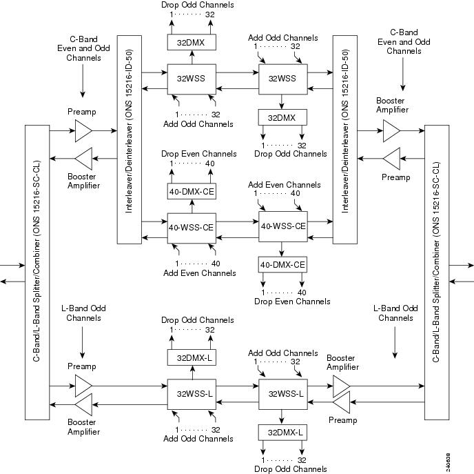
An example of a 112-channel C-band plus L-band ROADM node is shown in Figure 13-45. It operates in a similar manner to the 104-channel ROADM node shown in Figure 13-44, except that there are 40 odd C-band channels instead of 32.
Figure 13-45 112-Channel C-Band plus L-Band ROADM Node
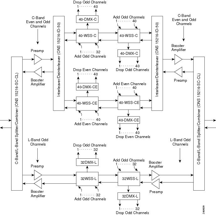
13.15 Wavelength Drifted Channel Automatic Shutdown
The wavelength drifted channel automatic shutdown feature detects wavelength instability or wavelength drift on the source port of the card connected to an MSTP multiplexer. The channel photodiode or optical channel monitor (OCM) associated with a variable optical attenuator (VOA) is used to detect the power fluctuation.
The wavelength drifted channel automatic shutdown feature is supported on 40-SMR1-C, 40-SMR2-C, 80-WXC-C, 40-WXC-C, and 40-WSS-C cards. The 40-SMR1-C, 40-SMR2-C, and 80-WXC-C cards have the OCM devices connected to the ADD port, which detect the power fluctuation. The 40-WSS-C and 40-WXC-C cards do not detect the power fluctuation on their ADD ports because the Add photodiode is located before the filtering stage. The different ports on each card detect the power fluctuation. Table 13-3 lists the ports on which the power fluctuation is detected.
|
|
|
|
|---|---|---|
When the card exceeds the OPT-PWR-DEG-LOW threshold value 16 times in 24 hours, the WVL-DRIFT-CHAN-OFF alarm is raised. When the WVL-DRIFT-CHAN-OFF alarm is raised, the VOA associated to that port is moved to the automatic VOA shutdown (AVS) state, which shuts down the channel.
For more information on the severity level of the conditions and procedure to clear the alarms, see Cisco ONS 15454 DWDM Troubleshooting Guide .
For more information on how to enable or disable this feature, see the G315 Enable or Disable the Wavelength Drifted Channel Automatic Shutdown Feature.
 Feedback