- Preface
- Cisco ONS Documentation Roadmap for Release 9.4
- Chapter 1, Install the Cisco ONS 15454, ONS 15454 M2, and ONS 15454 M6 Shelf
- Chapter 2, Connecting the PC and Logging into the GUI
- Chapter 3, Install the Control Cards
- Chapter 4, Setup Optical Service Channel Cards
- Chapter 5, Optical Amplifier Cards
- Chapter 6, Provision Multiplexer and Demultiplexer Cards
- Chapter 7, Setup Tunable Dispersion Compensating Units
- Chapter 8, Provision Protection Switching Module
- Chapter 9, Optical Add/Drop Cards
- Chapter 10, Reconfigurable Optical Add/Drop Cards
- Chapter 11, Provision Transponder and Muxponder Cards
- Chapter 12, Node Reference
- Chapter 13, Network Reference
- Chapter 14, Turn Up a Node
- Chapter 15, Perform Node Acceptance Tests
- Chapter 16, Turn Up a Network
- Chapter 17, Create Optical Channel Circuits and Provisionable Patchcords
- Chapter 18, Monitor Performance
- Chapter 19, Manage the Node
- Chapter 20, Alarm and TCA Monitoring and Management
- Chapter 21, Change DWDM Card Settings
- Chapter 22, Manage Network Connectivity
- Chapter 23, Upgrade, Add, and Remove Cards and Nodes
- Chapter 24, Maintain the Node
- Chapter 25, Security Reference
- Chapter 26, Timing Reference
- Chapter 27, SNMP
- Appendix A, CTC Operation, Information, and Shortcuts
- Appendix B, Hardware Specifications
- Appendix C, Administrative and Service States
- Appendix D, Configure GE_XP, 10GE_XP, GE_XPE, and 10GE_XPE Cards Using PCLI
- Appendix E, Pseudo Command Line Interface Reference
- Appendix F, Fiber and Connector Losses in Raman Link Configuration
- Appendix G, Card Features
- Appendix H, Network Element Defaults
Provision Optical Add/Drop Cards
This chapter describes optical add/drop cards used in Cisco ONS 15454 dense wavelength division multiplexing (DWDM) networks. For card safety and compliance information, refer to the Regulatory Compliance and Safety Information for Cisco CPT and Cisco ONS Platforms document.

Note![]() The cards described in this chapter are supported on the Cisco ONS 15454, Cisco ONS 15454 M6, Cisco ONS 15454 M2 platforms, unless noted otherwise.
The cards described in this chapter are supported on the Cisco ONS 15454, Cisco ONS 15454 M6, Cisco ONS 15454 M2 platforms, unless noted otherwise.
Note![]() Unless otherwise specified, “ONS 15454” refers to both ANSI and ETSI shelf assemblies.
Unless otherwise specified, “ONS 15454” refers to both ANSI and ETSI shelf assemblies.
- Card Overview
- Safety Labels
- AD-1C-xx.x Card
- Related Procedures for AD-1C-xx.x Card
- AD-2C-xx.x Card
- Related Procedures for AD-2C-xx.x Card
- AD-4C-xx.x Card
- Related Procedures for AD-4C-xx.x Card
- AD-1B-xx.x Card
- Related Procedures for AD-1B-xx.x Card
- AD-4B-xx.x Card
- Related Procedures for AD-4B-xx.x Card
9.1 Card Overview
The card overview section contains card overview, software compatibility, interface class, and channel allocation information for optical add/drop cards.
Note![]() Each card is marked with a symbol that corresponds to a slot (or slots) on the ONS 15454 shelf assembly. The cards are then installed into slots displaying the same symbols. For a list of slots and symbols, see the “Card Slot Requirements” section in the Cisco ONS 15454 Hardware Installation Guide.
Each card is marked with a symbol that corresponds to a slot (or slots) on the ONS 15454 shelf assembly. The cards are then installed into slots displaying the same symbols. For a list of slots and symbols, see the “Card Slot Requirements” section in the Cisco ONS 15454 Hardware Installation Guide.
Optical add/drop cards are divided into two groups: band optical add/drop multiplexer (OADM) cards and channel OADM cards. Band OADM cards add and drop one or four bands of adjacent channels. The cards in this chapter, including the 4-Band OADM (AD-4B-xx.x) and the 1-Band OADM (AD-1B-xx.x) are utilized only in the C band. Channel OADM cards add and drop one, two, or four adjacent channels; they include the 4-Channel OADM (AD-4C-xx.x), the 2-Channel OADM (AD-2C-xx.x), and the 1-Channel OADM (AD-1C-xx.x).
Note![]() For information about L band add and drop capability, see Chapter10, “Provision Reconfigurable Optical Add/Drop Cards”
For information about L band add and drop capability, see Chapter10, “Provision Reconfigurable Optical Add/Drop Cards”
9.1.1 Card Summary
Table 9-1 lists and summarizes the functions of the optical add/drop cards.
|
|
|
|
|---|---|---|
|
|
The AD-1C-xx.x card has three sets of ports located on the faceplate. It operates in Slots 1 to 6 and 12 to 17. |
See the “AD-1C-xx.x Card” section. |
|
|
The AD-2C-xx.x card has four sets of ports located on the faceplate. It operates in Slots 1 to 6 and 12 to 17. |
See the “AD-2C-xx.x Card” section. |
|
|
The AD-4C-xx.x card has six sets of ports located on the faceplate. It operates in Slots 1 to 6 and 12 to 17. |
See the “AD-4C-xx.x Card” section. |
|
|
The AD-1B-xx.x card has three sets of ports located on the faceplate. It operates in Slots 1 to 6 and 12 to 17. |
See the “AD-1B-xx.x Card” section. |
|
|
The AD-4B-xx.x card has six sets of ports located on the faceplate. It operates in Slots 1 to 6 and 12 to 17. |
See the “AD-4B-xx.x Card” section. |
9.1.2 Card Compatibility
Table 9-2 lists the CTC software compatibility for each optical add/drop card.
|
|
|
|
|
|
|
|
|
|
|
|
|
|
|
|
|
|---|---|---|---|---|---|---|---|---|---|---|---|---|---|---|---|
9.1.3 Interface Classes
The AD-1C-xx.x, AD-2C-xx.x, AD-4C-xx.x, AD-1B-xx.x, and AD-4B-xx.x cards have different input and output optical channel signals depending on the interface card where the input signal originates from. The input interface cards have been grouped in classes listed in Table 9-3 . The subsequent tables list the optical performances and output power of each interface class.
Table 9-4 lists the optical performance parameters for 40-Gbps cards that provide signal input to the optical add/drop cards.
|
|
|
|
|
|||
|---|---|---|---|---|---|---|
|
|
|
(if appl.) |
|
(if appl.) |
|
(if appl.) |
Maximum BER2 |
||||||
OSNR 1 sensitivity |
||||||
| Transmitted Power Range3 |
||||||
40-Gbps multirate transponder/40-Gbps FEC transponder (40E-TXP-C, and 40ME-TXP-C) |
||||||
|
3.These values, decreased by patchcord and connector losses, are also the input power values for the OADM cards. |
Table 9-5 lists the optical performance parameters for 40-Gbps cards that provide signal input to the optical add/drop cards.
|
|
|
|
|
|
|||
|---|---|---|---|---|---|---|---|
|
|
|
(if appl.) |
|
(if appl.) |
|
|
(if appl.) |
Maximum BER5 |
|||||||
OSNR 1 sensitivity |
|||||||
| Transmitted Power Range6 |
|||||||
10-Gbps multirate transponder/10-Gbps FEC transponder (TXP_MR_10G) |
|||||||
10-Gbps multirate transponder/10-Gbps FEC transponder (TXP_MR_10E) |
|||||||
|
6.These values, decreased by patchcord and connector losses, are also the input power values for the OADM cards. |
2.5-Gbps cards that provide signal input to the optical add/drop cards have the interface performance parameters listed in Table 9-6 .
|
|
|
|
|
|
|
|
||||
|---|---|---|---|---|---|---|---|---|---|---|
|
|
|
(if appl.) |
|
(if appl.) |
|
|
(if appl.) |
|
(if appl.) |
|
| Transmitted Power Range7 |
||||||||||
|
7.These values, decreased by patchcord and connector losses, are also the input power values for the OADM cards. |
9.1.4 DWDM Card Channel Allocation Plan
ONS 15454 DWDM channel OADM and band OADM cards are designed for use with specific channels in the C band. In most cases, the channels for these cards are either numbered (for example, 1 to 32) or delimited (odd or even). Client interfaces must comply with these channel assignments to be compatible with the ONS 15454 system.
Table 9-7 lists the channel IDs and wavelengths assigned to the C-band DWDM channels.
Note![]() In some cases, a card uses only some or all of the channels listed in a band. Also, some cards use channels on the 100-GHz ITU-T grid while others use channels on the 50-GHz ITU-T grid. See specific card descriptions in Appendix B, “Hardware Specifications,” for more details.
In some cases, a card uses only some or all of the channels listed in a band. Also, some cards use channels on the 100-GHz ITU-T grid while others use channels on the 50-GHz ITU-T grid. See specific card descriptions in Appendix B, “Hardware Specifications,” for more details.
|
|
|
|
|
|
|
|---|---|---|---|---|---|
9.2 Safety Labels
For information about safety labels, see the “Class 1M Laser Product Cards” section.
9.3 AD-1C-xx.x Card
Note![]() For AD-1C-xx.x card specifications, see the “AD-1C-xx.x Card Specifications” section in the Hardware Specifications document.
For AD-1C-xx.x card specifications, see the “AD-1C-xx.x Card Specifications” section in the Hardware Specifications document.
The 1-Channel OADM (AD-1C-xx.fx) card passively adds or drops one of the 32 channels utilized within the 100-GHz-spacing of the DWDM card system. Thirty-two versions of this card—each designed only for use with one wavelength—are used in the ONS 15454 DWDM system. Each wavelength version of the card has a different part number. The AD-1C-xx.x can be installed in Slots 1 to 6 and 12 to 17.
The AD-1C-xx.x has the following internal features:
- Two cascaded passive optical interferential filters perform the channel add and drop functions.
- One software-controlled variable optical attenuator (VOA) regulates the optical power of the inserted channel.
- Software-controlled VOA regulates the insertion loss of the express optical path.
- VOA settings and functions, photodiode detection, and alarm thresholds, are internally controlled.
- Virtual photodiodes (firmware calculations of port optical power) at the common DWDM output and input ports are monitored within the software.
9.3.1 Faceplate and Block Diagrams
Figure 9-1 shows the AD-1C-xx.x faceplate.
Figure 9-1 AD-1C-xx.x Faceplate

For information on safety labels for the card, see the “Safety Labels” section.
Figure 9-2 shows a block diagram of the AD-1C-xx.x card.
Figure 9-2 AD-1C-xx.x Block Diagram

Figure 9-3 shows the AD-1C-xx.x optical module functional block diagram.
Figure 9-3 AD-1C-xx.x Optical Module Functional Block Diagram
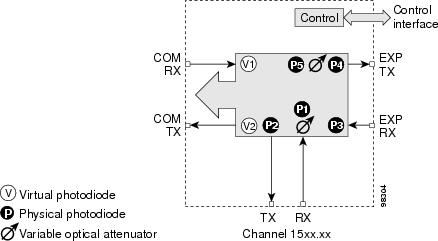
9.3.2 Power Monitoring
Physical photodiodes P1 through P4 and virtual photodiodes V1 and V2 monitor the power for the AD-1C-xx.x card. The returned power level values are calibrated to the ports as shown in Table 9-8 .
|
|
|
|
|---|---|---|
For information on the associated TL1 AIDs for the optical power monitoring points, refer the “CTC Port Numbers and TL1 Aids” section in Cisco ONS SONET TL1 Command Guide, Release 9.2.1.
9.3.3 AD-1C-xx.x Card Functions
- Card level indicators—Table G-4
- “Port-Level Indicators” section
9.3.4 Related Procedures for AD-1C-xx.x Card
The following section lists procedures and tasks related to the configuration of the AD-1C-xx.x card:
- G30 Install the DWDM Cards
- G37 Run Automatic Node Setup
- G59 Create, Delete, and Manage Optical Channel Network Connections
- G51 Verify DWDM Node Turn Up
- NTP-G74 Monitor DWDM Card Performance
- G106 Reset Cards Using CTC
- NTP-G107 Remove Permanently or Remove and Replace DWDM Cards
- G119 Power Down the Node
9.4 AD-2C-xx.x Card
Note![]() For AD-2C-xx.x card specifications, see the “AD-2C-xx.x Card Specifications” section in theHardware Specifications document.
For AD-2C-xx.x card specifications, see the “AD-2C-xx.x Card Specifications” section in theHardware Specifications document.
The 2-Channel OADM (AD-2C-xx.x) card passively adds or drops two adjacent 100-GHz channels within the same band. Sixteen versions of this card—each designed for use with one pair of wavelengths—are used in the ONS 15454 DWDM system. The card bidirectionally adds and drops in two different sections on the same card to manage signal flow in both directions. Each version of the card has a different part number.
The AD-2C-xx.x has the following features:
- Passive cascade of interferential filters perform the channel add and drop functions.
- Two software-controlled VOAs in the add section, one for each add port, regulate the optical power of inserted channels.
- Software-controlled VOAs regulate insertion loss on express channels.
- VOA settings and functions, photodiode detection, and alarm thresholds are internally controlled.
- Virtual photodiodes (firmware calculation of port optical power) at the common DWDM output and input ports are monitored within the software.
9.4.1 Faceplate and Block Diagrams
Figure 9-4 shows the AD-2C-xx.x faceplate.
Figure 9-4 AD-2C-xx.x Faceplate

For information on safety labels for the card, see the “Safety Labels” section.
Figure 9-5 shows a block diagram of the AD-2C-xx.x card.
Figure 9-5 AD-2C-xx.x Block Diagram
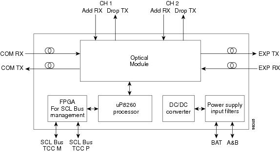
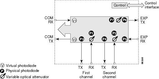
Figure 9-6 shows the AD-2C-xx.x optical module functional block diagram.
Figure 9-6 AD-2C-xx.x Optical Module Functional Block Diagram
9.4.2 Wavelength Pairs
The AD-2C-xx.x cards are provisioned for the wavelength pairs listed in Table 9-9 . In this table, channel IDs are given rather than wavelengths. To compare channel IDs with the actual wavelengths they represent, see wavelengths in Table 9-7.
|
|
|
|---|---|
9.4.3 Power Monitoring
Physical photodiodes P1 through P10 and virtual photodiodes V1 and V2 monitor the power for the AD-2C-xx.x card. The returned power level values are calibrated to the ports as shown in Table 9-10 .
|
|
|
|
|---|---|---|
For information on the associated TL1 AIDs for the optical power monitoring points, refer the “CTC Port Numbers and TL1 Aids” section in Cisco ONS SONET TL1 Command Guide, Release 9.2.1.
9.4.4 AD-2C-xx.x Card Functions
- Card level indicators—Table G-4
- “Port-Level Indicators” section
9.4.5 Related Procedures for AD-2C-xx.x Card
The following section lists procedures and tasks related to the configuration of the AD-2C-xx.x card:
- G30 Install the DWDM Cards
- G37 Run Automatic Node Setup
- G59 Create, Delete, and Manage Optical Channel Network Connections
- G51 Verify DWDM Node Turn Up
- NTP-G74 Monitor DWDM Card Performance
- G106 Reset Cards Using CTC
- NTP-G107 Remove Permanently or Remove and Replace DWDM Cards
- G119 Power Down the Node
9.5 AD-4C-xx.x Card
Note![]() For AD-4C-xx.x card specifications, see the “AD-4C-xx.x Card Specifications” section in the Hardware Specifications document.
For AD-4C-xx.x card specifications, see the “AD-4C-xx.x Card Specifications” section in the Hardware Specifications document.
The 4-Channel OADM (AD-4C-xx.x) card passively adds or drops all four 100-GHz-spaced channels within the same band. Eight versions of this card—each designed for use with one band of wavelengths—are used in the ONS 15454 DWDM system. The card bidirectionally adds and drops in two different sections on the same card to manage signal flow in both directions. There are eight versions of this card with eight part numbers.
The AD-4C-xx.x has the following features:
- Passive cascade of interferential filters perform the channel add and drop functions.
- Four software-controlled VOAs in the add section, one for each add port, regulate the optical power of inserted channels.
- Two software-controlled VOAs regulate insertion loss on express and drop path, respectively.
- Internal control of the VOA settings and functions, photodiode detection, and alarm thresholds.
- Software-monitored virtual photodiodes (firmware calculation of port optical power) at the common DWDM output and input ports.
9.5.1 Faceplate and Block Diagrams
Figure 9-7 shows the AD-4C-xx.x faceplate.
Figure 9-7 AD-4C-xx.x Faceplate

For information on safety labels for the card, see the “Safety Labels” section.
Figure 9-8 shows a block diagram of the AD-4C-xx.x card.
Figure 9-8 AD-4C-xx.x Block Diagram
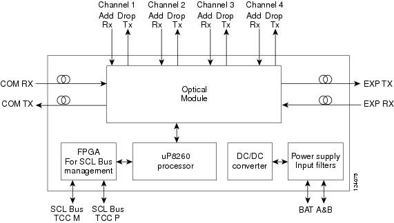
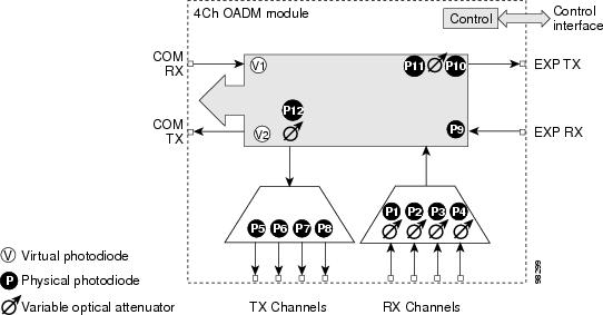
Figure 9-9 shows the AD-4C-xx.x optical module functional block diagram.
Figure 9-9 AD-4C-xx.x Optical Module Functional Block Diagram
9.5.2 Wavelength Sets
The AD-4C-xx.x cards are provisioned for the sets of four 100-GHz-spaced wavelengths shown Table 9-11.
|
|
|
|---|---|
9.5.3 Power Monitoring
Physical photodiodes P1 through P10 and virtual photodiodes V1 and V2 monitor the power for the AD-4C-xx.x card. The returned power level values are calibrated to the ports as shown in Table 9-12 .
|
|
|
|
|---|---|---|
For information on the associated TL1 AIDs for the optical power monitoring points, refer the “CTC Port Numbers and TL1 Aids” section in Cisco ONS SONET TL1 Command Guide, Release 9.2.1.
9.5.4 AD-4C-xx.x Card Functions
- Card level indicators—Table G-4
- “Port-Level Indicators” section
9.5.5 Related Procedures for AD-4C-xx.x Card
The following section lists procedures and tasks related to the configuration of the AD-4C-xx.x card:
- G30 Install the DWDM Cards
- G37 Run Automatic Node Setup
- G59 Create, Delete, and Manage Optical Channel Network Connections
- G51 Verify DWDM Node Turn Up
- NTP-G74 Monitor DWDM Card Performance
- G106 Reset Cards Using CTC
- NTP-G107 Remove Permanently or Remove and Replace DWDM Cards
- G119 Power Down the Node
9.6 AD-1B-xx.x Card
Note![]() For AD-1B-xx.x card specifications, see the “AD-1B-xx.x Card Specifications” section in the Hardware Specifications document.
For AD-1B-xx.x card specifications, see the “AD-1B-xx.x Card Specifications” section in the Hardware Specifications document.
The 1-Band OADM (AD-1B-xx.x) card passively adds or drops a single band of four adjacent 100-GHz-spaced channels. Eight versions of this card with eight different part numbers—each version designed for use with one band of wavelengths—are used in the ONS 15454 DWDM system. The card bidirectionally adds and drops in two different sections on the same card to manage signal flow in both directions. This card can be used when there is asymmetric adding and dropping on each side (east or west) of the node; a band can be added or dropped on one side but not on the other.
The AD-1B xx.x can be installed in Slots 1 to 6 and 12 to17 and has the following features:
- Passive cascaded interferential filters perform the channel add and drop functions.
- Two software-controlled VOAs regulate the optical power flowing in the express and drop OADM paths (drop section).
- Output power of the dropped band is set by changing the attenuation of the VOA drop.
- The VOA express is used to regulate the insertion loss of the express path.
- VOA settings and functions, photodiode detection, and alarm thresholds are internally controlled.
- Virtual photodiode (firmware calculation of port optical power) at the common DWDM output are monitored within the software.
9.6.1 Faceplate and Block Diagrams
Figure 9-10 shows the AD-1B-xx.x faceplate.
Figure 9-10 AD-1B-xx.x Faceplate

For information on safety labels for the card, see the “Safety Labels” section.
Figure 9-11 shows a block diagram of the AD-1B-xx.x card.
Figure 9-11 AD-1B-xx.x Block Diagram
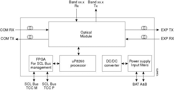
Figure 9-12 shows the AD-1B-xx.x optical module functional block diagram.
Figure 9-12 AD-1B-xx.x Optical Module Functional Block Diagram
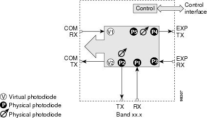
9.6.2 Power Monitoring
Physical photodiodes P1 through P4 and virtual photodiodes V1 and V2 monitor the power for the AD-1B-xx.x card. The returned power level values are calibrated to the ports as shown in Table 9-13 .
|
|
|
|
|---|---|---|
For information on the associated TL1 AIDs for the optical power monitoring points, refer the “CTC Port Numbers and TL1 Aids” section in Cisco ONS SONET TL1 Command Guide, Release 9.2.1.
9.6.3 AD-1B-xx.x Card Functions
- Card level indicators—Table G-4
- “Port-Level Indicators” section
9.6.4 Related Procedures for AD-1B-xx.x Card
The following section lists procedures and tasks related to the configuration of the AD-1B-xx.x card:
- G30 Install the DWDM Cards
- G37 Run Automatic Node Setup
- G59 Create, Delete, and Manage Optical Channel Network Connections
- G51 Verify DWDM Node Turn Up
- NTP-G74 Monitor DWDM Card Performance
- G106 Reset Cards Using CTC
- NTP-G107 Remove Permanently or Remove and Replace DWDM Cards
- G119 Power Down the Node
9.7 AD-4B-xx.x Card
The 4-Band OADM (AD-4B-xx.x) card passively adds or drops four bands of four adjacent 100-GHz-spaced channels. Two versions of this card with different part numbers—each version designed for use with one set of bands—are used in the ONS 15454 DWDM system. The card bidirectionally adds and drops in two different sections on the same card to manage signal flow in both directions. This card can be used when there is asymmetric adding and dropping on each side (east or west) of the node; a band can be added or dropped on one side but not on the other.
The AD1B-xx.x can be installed in Slots 1 to 6 and 12 to 17 and has the following features:
- Five software-controlled VOAs regulate the optical power flowing in the OADM paths.
- Output power of each dropped band is set by changing the attenuation of each VOA drop.
- The VOA express is used to regulate the insertion loss of the express path.
- VOA settings and functions, photodiode detection, and alarm thresholds are internally controlled.
- Virtual photodiode (firmware calculation of port optical power) at the common DWDM output port are monitored within the software.
9.7.1 Faceplate and Block Diagrams
Figure 9-13 shows the AD-4B-xx.x faceplate.
Figure 9-13 AD-4B-xx.x Faceplate

For information on safety labels for the card, see the “Safety Labels” section.
Figure 9-14 shows a block diagram of the AD-4B-xx.x card.
Figure 9-14 AD-4B-xx.x Block Diagram
Figure 9-15 shows the AD-4B-xx.x optical module functional block diagram.
Figure 9-15 AD-4B-xx.x Optical Module Functional Block Diagram
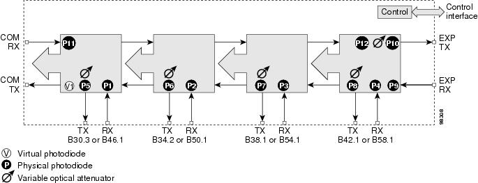
9.7.2 Power Monitoring
Physical photodiodes P1 through P11 and virtual photodiode V1 monitor the power for the AD-4B-xx.x card. The returned power level values are calibrated to the ports as shown in Table 9-14 .
|
|
|
|
|---|---|---|
For information on the associated TL1 AIDs for the optical power monitoring points, refer the “CTC Port Numbers and TL1 Aids” section in Cisco ONS SONET TL1 Command Guide, Release 9.2.1.
9.7.3 AD-4B-xx.x Card Functions
- Card level indicators—Table G-4
- “Port-Level Indicators” section
9.7.4 Related Procedures for AD-4B-xx.x Card
The following section lists procedures and tasks related to the configuration of the AD-4B-xx.x card:
- G30 Install the DWDM Cards
- G37 Run Automatic Node Setup
- G59 Create, Delete, and Manage Optical Channel Network Connections
- G51 Verify DWDM Node Turn Up
- NTP-G74 Monitor DWDM Card Performance
- G106 Reset Cards Using CTC
- NTP-G107 Remove Permanently or Remove and Replace DWDM Cards
- G119 Power Down the Node
 Feedback