Workflow for ROADM Split Nodes, Release 10.x.x
The ROADM Node Split feature allows the configuration of the ROADM node to have separate Network Elements for each of the line sides leading to the complete separation of different ROADM degrees.
Overview
The ROADM node split feature enables per-degree separation of a multi-degree ROADM node into multiple multi-shelf nodes. The feature allows the ROADM node to have separate Network Elements(NEs) for each of the line sides leading to the complete separation of different ROADM degrees. This helps to prevent losing the whole NE manageability in the case of failure.
-
Resiliency against a single side or node controller failure.
-
Ability to upgrade the node software one degree at a time, thereby enabling improved planned maintenance. Upgrades can be performed on the low priority nodes (with less traffic) first to ensure that the upgrade is successful before attempting to upgrade the high priority nodes.
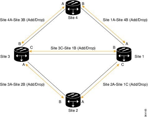
The following diagram shows a directional A/D multi-degree ROADM node configuration. In this scenario if Site 1 has node failure, the traffic between Site 4 - Site 1, Site 3 -Site 1, and Site 2 - Site 1 are impacted.
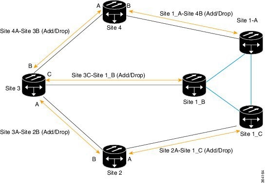
The following diagram shows a split ROADM configuration after Site 1 is split. In case there is node failure at Site 1_C, traffic between Site 2 - Site 1_C goes down but traffic between Site 4 -Site 1_A and Site 3 - Site 1_B remain unaffected.
In a 4-degree ROADM node, the four sides are split into four NEs and in an 8-degree ROADM node, the eight sides are split into eight NEs. To manage these nodes, virtual passive devices are used. The virtual passive devices are connected using virtual PPCs that can be configured in CTC. It is possible to migrate legacy ROADM configurations to split ROADM configurations using CTC - CTP collaboration.
Supported Packages
The ROADM split node feature is supported in the following software packages:
-
NCS Fixed Grid package
-
Cisco ONS 15454 DWDM full package
Supported Configurations
The ROADM split node feature supports the following configurations:
-
A 40 or 80 channel two-degree ROADM node with direct interconnection between the 80-WXC-C cards.
-
A 40 channel two-degree ROADM node with direct interconnection between the 40-SMR1-C cards.
-
A directional colored A/D multi-degree ROADM configuration with PP-MESH-4 or PP-MESH-8 mesh patch panel trays and 80-WXC-C cards.
 Note |
The 80-WXC-C cards are configured in the BIDI mode. |
Prerequisites and Restrictions
The following are the prerequisites and restrictions for configuring the split ROADM node.
Prerequisites for Configuring the Split ROADM Node
-
The CTP layout reports and XML files must be generated for both pre and post-split networks.
-
All the hardware requirements listed in the CTP post-split site BoM must be available.
-
Complete the NTP-G103 Backing Up the Database procedure.
Restrictions for Configuring the Split ROADM Node
-
When the security mode is enabled on a node and PPCs are provisioned, the node cannot be split due to connectivity issues.
-
Network-level alarm correlation is not supported in split nodes.
-
If the side is connected through a PPC link prior to the node split, perform the following steps:
-
Delete all the circuits that pass through the PPC side.
-
Delete the PPC.
Note
If the circuit type is OCHNC, the PPC can be deleted without deleting the OCHNC circuit. For OCHCC circuits, delete the circuit first before deleting the PPC using the procedure, DLP-G347 Deleting Optical Channel Client Connections.
-
Perform the node split procedure.
-
Provision the PPC again after the node split operation is complete.
-
Re-provision the circuits.
-
Prerequisites for Reverting to the Pre-split ROADM Configuration
-
Nodes must be in the post-split state.
-
The post-split and pre-split node layout must be the same.
-
Each post-split side must reside in separate shelves.
-
The pre-split database back up must be available.
-
The R10.5.2 software must be installed on the network .
Migration of Legacy ROADM Nodes to Split ROADM Nodes
During the node split operation, traffic passing through the side that is undergoing split is impacted. Traffic restores after the split operation is completed for that side.
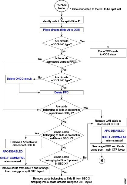
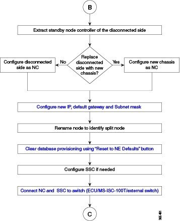
ROADM Node Split Configuration Flowchart
This flowchart focuses on specific sets of configuration instructions based on your decisions. But these instructions, and in particular the sequence of tasks described here, are recommended.
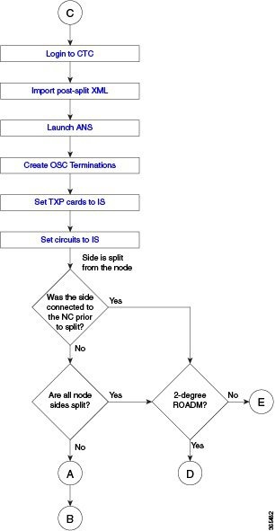
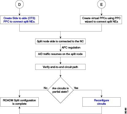
Workflow for the Split ROADM Configuration
To migrate a legacy ROADM node to a split ROADM configuration, perform the following tasks:
|
Task |
Detailed Steps |
||
|---|---|---|---|
|
Task 1 : Identify node side. |
Identify the node side to be split. For example, Side A.
|
||
|
Task 2: Place the add/drop and passthrough circuits in the OOS state. |
Place the OCHNC, OCHCC, or OCHTRAIL circuits on Side A in the OOS,DSBLD (ANSI) or Locked,disabled (ETSI) state using the Edit Circuit dialog box. If the circuit type is OCHNC, you must place the TXP cards in the OOS-MA,DSBLD (ANSI) or Locked,disabled (ETSI) service state. |
||
|
Task 3:Separate the subtending shelf. |
|
||
|
Task 4:Configure the disconnected side as the node controller. |
|
||
|
Task 5 (Optional): Configure subtending shelves. |
Configure new or existing subtending shelves for the split node using the LCD. The parameters used are [MS=Y: Shelf ID= N: VLAN=Y]; where N varies from 2 to 50.
|
||
|
Task 6: Connect the node controller and the subtending shelves to the ethernet switch. |
Connect the node controller and the subtending shelves to the ethernet switch [ECU (M6), MS-ISC-100T or Catalyst 3650 (M12), ] using the procedure, NTP-G309 Connect the ONS 15454 M6 and the ONS 15454 in a Mixed Multishelf Configuration. |
||
|
Task 7: Import the post-split XML file in CTC. |
Login to CTC and import the post-split XML file using the procedure, NTP-G143 Import the Cisco Transport Planner NE Update Configuration File. Apply all the configurations. |
||
|
Task 8: Install the DWDM cards. |
Install the DWDM cards based on the post-split CTP shelf layout report using the procedures, NTP-G30 Installing the DWDM Cards and NTP-G179 Installing the Transponder and Muxponder Cards . |
||
|
Task 9: Launch ANS. |
Launch ANS using the procedure, NTP-G37 Running Automatic Node Setup. |
||
|
Task 10: Create OSC terminations. |
Create OSC terminations using the procedure, NTP-G38 Provisioning OSC Terminations. |
||
|
Task 11:Set TXP cards in service. |
Set TXP cards in service. |
||
|
Task 12: Set circuits in service. |
Set circuits that were placed in OOS,DSBLD (ANSI) or Locked,disabled (ETSI) in Task 2 back to service using the Edit Circuit dialog box. |
||
|
Task 13: Create provisional patchcords (PPCs) between the post-split nodes. |
|
||
|
Wait for 10 minutes for APC to complete any power regulations. Add/drop traffic resumes on the split node. |
|||
|
Task 14: Complete split procedure for associated sides. |
For pass-through traffic to resume, all the associated sides must be split. Repeat tasks 1 through 14 for all sides that need to be split. |
||
|
Task 15: Clear the database provisioning on the NC. |
Clear the database provisioning on the NC by using "Reset to NE Defaults" button located in the node view > Provisioning > General >Reset to NE Defaults tab. |
||
|
Task 16: Verify end-to end circuit connectivity |
To verify end-to end connectivity of the circuits, use the Show detailed map option in CTC. |
||
|
Task 17: Reconfigure circuits in PARTIAL state. |
|
||
|
The split ROADM configuration is complete. |
|||
In R10.5.2, it is possible to create a split ROADM configuration where the side to be split can be replaced with a different chassis. In the example below, Side A is replaced with a new chassis, A'.
|
Task |
Detailed Steps |
||
|---|---|---|---|
|
Task 1 : Identify node side. |
Identify the node side to be split. For example, Side A.
|
||
|
Task 2: Place the add/drop and passthrough circuits in the OOS state. |
Place the OCHNC, OCHCC, or OCHTRAIL circuits on Side A in the OOS,DSBLD (ANSI) or Locked,disabled (ETSI) state using the Edit Circuit dialog box. If the circuit type is OCHNC, you must place the TXP cards in the OOS-MA,DSBLD (ANSI) or Locked,disabled (ETSI) service state. |
||
|
Task 3:Separate the subtending shelf. |
|
||
|
Task 4:Configure the new chassis A' as the node controller.
|
|
||
|
Task 5 (Optional): Configure subtending shelves. |
Configure new or existing subtending shelves for the split node using the LCD. The parameters used are [MS=Y: Shelf ID= N: VLAN=Y]; where N varies from 2 to 50.
|
||
|
Task 6: Connect the node controller and the subtending shelves to the ethernet switch. |
Connect the node controller and the subtending shelves to the ethernet switch [ECU (M6), MS-ISC-100T or Catalyst 3650 (M12), ] using the procedure, NTP-G309 Connect the ONS 15454 M6 and the ONS 15454 in a Mixed Multishelf Configuration. |
||
|
Task 7: Move the cards from Side A to chassis A' |
Move all the cards from Side A to the new chassis A'. Ensure all the cards are in active or standby mode. |
||
|
Task 8: Import the post-split XML file in CTC. |
Login to CTC and import the post-split XML file using the following steps:
|
||
|
Task 9: Create OSC terminations. |
Create OSC terminations using the procedure, NTP-G38 Provisioning OSC Terminations. |
||
|
Task 10: Set TXP cards in service. |
Set TXP cards in service. |
||
|
Task 11: Set circuits in service. |
Set circuits that were placed in OOS,DSBLD (ANSI) or Locked,disabled (ETSI) in Task 2 back to service using the Edit Circuit dialog box. |
||
|
Task 12: Create provisional patchcords (PPCs) between the post-split nodes. |
|
||
|
Wait for 15 minutes for APC to complete any power regulations. Add/drop traffic resumes on the split node. |
|||
|
Task 13: Complete split procedure for associated sides. |
For pass-through traffic to resume, all the associated sides must be split. Repeat tasks 1 through 12 for all sides that need to be split. |
||
|
Task 14: Clear the database provisioning on the NC. |
Clear the database provisioning on the NC by using "Reset to NE Defaults" button located in the node view > Provisioning > General >Reset to NE Defaults tab. |
||
|
Task 15: Verify end-to end circuit connectivity |
To verify end-to end connectivity of the circuits, use the Show detailed map option in CTC. |
||
|
Task 16: Reconfigure circuits in PARTIAL state. |
|
||
|
The split ROADM configuration is complete. |
|||
Reverting a Split ROADM Configuration to a Pre-split Configuration
To revert to pre-split configuration, perform the following steps:
|
Task |
Detailed Steps |
|---|---|
|
Task 1 : Prepare the nodes that are currently existing as separate NEs so that they can be subtended to the mastershelf. |
|
|
Task 2: Restore the database on the node that was the master shelf prior to the split. |
Restore the database using the procedure NTP-G104 Restoring the Database. |
|
Task 3: Connect the node controller and the subtending shelves to the ethernet switch. |
Connect the node controller and the subtending shelves to the ethernet switch [ECU (M6 or NCS 2015), MS-ISC-100T or Catalyst 3650 (M12), ] using the procedure, NTP-G309 Connect the ONS 15454 M6 and the ONS 15454 in a Mixed Multishelf Configuration. |
|
The revert procedure is complete. |
|
To revert a post-split configuration with chassis replacement, perform the following steps:
|
Task |
Detailed Steps |
|---|---|
|
Task 1: Revert the chassis A' to Side A |
To revert A' to Side A, perform the following steps :
|
|
Task 2 : Prepare the nodes that are currently existing as separate NEs so that they can be subtended to the mastershelf. |
|
|
Task 2: Restore the database on the node that was the master shelf prior to the split. |
Restore the database using the procedure NTP-G104 Restoring the Database. |
|
Task 3: Connect the node controller and the subtending shelves to the ethernet switch. |
Connect the node controller and the subtending shelves to the ethernet switch [ECU (M6 or NCS 2015), MS-ISC-100T or Catalyst 3650 (M12), ] using the procedure, NTP-G309 Connect the ONS 15454 M6 and the ONS 15454 in a Mixed Multishelf Configuration. |
|
The revert procedure is complete. |
|
 Feedback