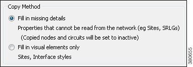
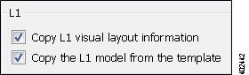
Plan Files and Templates

This chapter describes plans files and templates so that you understand their structure, and how templates are applied to plan files for visualization.

This section contains the following topics:

Plan Files

A plan file is comprised of tables that store information about a network, including topology, configuration information, traffic, failure state, and visual layout. WAE Design uses plan file information to perform simulations.

The WAE Design GUI can access remote servers to send and receive plan files.

Templates

A WAE Design template identifies how the plan file looks and can contain information that is not discovered. As such, templates are a convenient way to replicate manual changes across multiple plan files. For example, you can augment newly discovered plans with non-discoverable information.

No matter the discovery method, the way to make further visual enhancements to the plan file is using the WAE Design GUI, which can access remote servers to send and receive templates.

If using the augmented or manual method of discovery, the copy_from_template tool is used to either include more objects in the template, change the visual representation of them, or both. The resulting plan file is saved to an external archive or WAE Automation Server.

When saving a template from WAE Design to an archive or WAE Automation Server, template changes apply only to plan files collected after that template is saved. That is, those templates changes do not apply to historical plan files.

Example

The following figure shows the plan file and template workflow for applications. We recommend that you open the remote plan file, modify it in the WAE Design GUI to create the visual template, and save it to the remote archive or WAE Automation Server as a template (where it overwrites the earlier template).

The following figure also shows the workflow of using the WAE Design GUI to open plan files from and save plan files to the remote WAE Automation server, where they can then be deployed to the network.

Figure 1. Plan File and Template Flow Using the WAE Design GUI

Copy from Template

The File > Copy from Template tool lets you copy objects and their properties from a template to another file. By copying a template, you can augment newly discovered plans with non-discoverable information, such as sites, layouts, shared-risk link groups (SRLGs), external endpoints, and L1 objects.

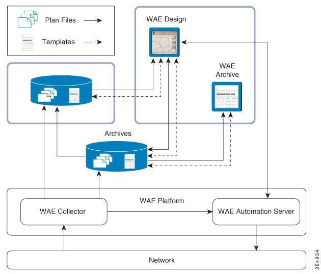
  • One common use is to use the CLI copy_from_template tool to automate the process of applying a template to newly discovered network plan files before saving them in an archive or WAE Automation Server. When you open the new plan file, you need not complete its layout or insert non-discovered objects. Note that this CLI copy_from_template tool has more functionality than in the GUI. For information, see the copy_from_template -help output.

    The copy_from_template tool is in $CARIDEN_HOME/bin, where $CARIDEN_HOME is the directory in which the Cisco WAE executables and binaries are installed. On Linux, the default $CARIDEN_HOME is /opt/cariden/software/mate/current.

  • Another use is to create one or more visual layouts in one plan file and copy the layouts into other plan files, thus avoiding repetitive efforts of recreating layouts. This practice is useful even for plans created outside of network discovery.

The selected properties or objects are copied from the template to the open plan file, and a report is displayed. If there are nodes or interfaces in the plan file that are not in the template, this might indicate that the discovered network has been changed, and the template is out of date. In this case, the report states that the template should be updated.

Note that you can individually import SRLGs, a Layer 1 model, a QoS model, demand groupings, external endpoints, and tags from one plan file to another, all from the File > Import menu. For information, see the Cisco WAE Design Integration and Development Guide.

Assign Nodes to Sites

In the WAE Design GUI, the visual layout is based on the schematic or geographic arrangement of sites and nodes. If nodes are within sites, this node-to-site assignment is not discoverable.

When layouts are copied from the template, nodes that are discovered are placed in the plan file as follows:

  • Each existing node without a parent site continues to exist without a parent.

  • If a discovered node is matched to a node within a site in an existing template, it is assigned to the same site.

  • If the node is new, it is assigned to a site based on the Node-to-Site Mapping (<NodeSiteMappingRules>) table in the template.

  • If WAE Design cannot assign the discovered node to an existing site, an ExtraNodes site is created and the unassigned node is placed there. This site appears at the top right of the plot.

Copy Missing Information

If any nodes, circuits, L1 nodes, or L1 links are down, the network discovery process omits them from the discovered plan file. Because a template used for network discovery typically contains these objects, it can fill in the missing objects to provide a complete visualization of the network. Whether these objects are set to inactive or active depends on the selected copy method.

Errors in network discovery can sometimes prevent node names, interface names, or IP addresses from being discovered correctly. The Copy from Template tool attempts to fill in the missing object information by matching nodes and interfaces in the two plans by name and IP address; for nodes that are in external ASes, it also checks the BGP-ID. For example, if the discovery process finds an IP address of an interface, but not its name, the tool looks for an interface in the template with a matching IP address, and then copies over the name from the template interface.

Copy Methods

The objects and properties that are copied depend on the selected method, as described in the following table.

Table 1. Copy from Template Methods

Copy from Template Method

Description

Fill in missing details

  • Copies L3 template layout, including site assignments for nodes.

  • Copies L3 nodes and circuits, and sets them to inactive.

  • For newly discovered L3 nodes, assigns nodes to sites based on the <NodeSiteMappingRules> table created using the Assign Sites to Nodes feature.

  • Copies non-discoverable L3 objects, such as SRLGs and AS relationships.

Fill in visual elements only

  • Copies L3 template layout.

  • For newly discovered L3 nodes, assigns nodes to sites based on the <NodeSiteMappingRules> table created using the Assign Sites to Nodes feature.

Copy L1 visual layout information

  • Copies template layout for L1 objects.

  • Site assignments are based on the site assignments in the template. Any L1 nodes that exist in the plan file but not in the template are placed in an ExtraL1Nodes site that is created for this purpose.

Copy the L1 model from the template

You cannot copy L1 objects without copying L3 objects (without "Fill in missing details" also being selected).

  • Copies template layout, including site assignments for L1 nodes.

  • Copies all L1 objects.

  • Site assignments are based on the site assignments in the template. Any L1 nodes that exist in the plan file but not in the template are placed in an ExtraL1Nodes site that is created for this purpose.

Copy from Template Steps

Procedure


Step 1

Choose File > Copy from Template.

Step 2

In the Template File field, enter or browse to the fully-qualified path and filename of the plan you are copying.

Step 3

Specify how to copy L3 values from the template into the plan.

Step 4

Specify how to match nodes in the plan with those in the template:

  • Name, then IP address, then BGP ID—Choose this option to match all nodes by name if possible, then by IP address, and then by BGP ID.

  • IP Address, then BGP ID, then Name—Choose this option to match all nodes by matching by IP address if possible, then by BGP ID, and then by name.

Step 5

Specify how to match interfaces in the plan with those in the template:

  • Name, then IP Address (if available)—Choose this option to match all interfaces and circuits by name if possible, and then by IP address.

  • IP Address (if available), then Name—Choose this option to match all interfaces and circuits by matching by IP address if possible, and then by name.

Step 6

(Optional) Specify how to copy L1 values from the template into the plan.

Step 7

(Optional) Choose which nodes to include by clicking Preview/Customize. From here you can click Edit to choose nodes, as well as set copied nodes to inactive. If the plan file contains nodes that the template does not contain, they are put into a site named ExtraNodes (for L3 nodes) or ExtraL1Nodes (for L1 nodes).

To view which circuits to include, click Next. You can click Edit to choose specific circuits or you can set the circuits to inactive. We recommend that you not use this option unless you also choose to include nodes associated with these circuits.

Step 8

Click OK.

Step 9

Look at the network plot to verify the success of the copied template.