Overview


Important


This document was last updated for Cisco WAE 7.2.1. The purpose of this document is to help you understand the basics of plan files and templates. As there have been new features and enhancements introduced in later releases, some options, images, or steps in this document may vary from the version you are using. For complete information, refer to the Cisco WAE Design User Guide on cisco.com for the required release.


This section contains the following topics:

Plan Files and Templates

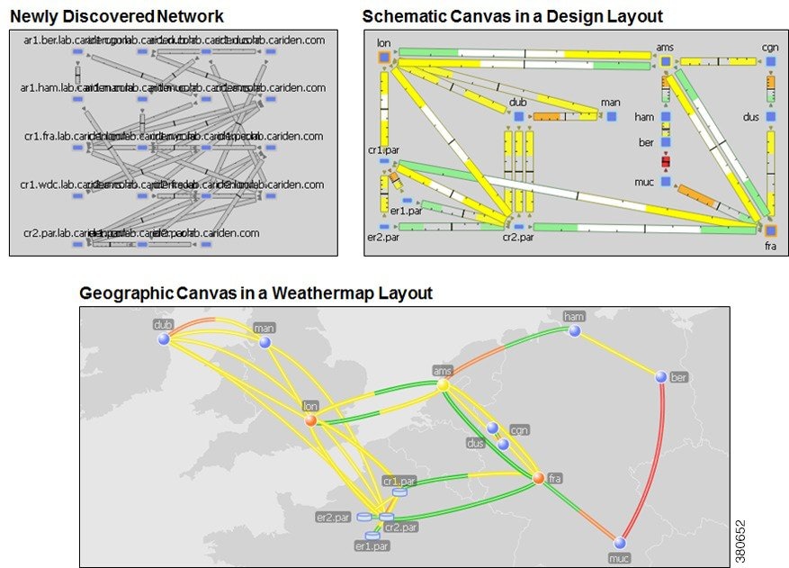
The unit of data storage that is displayed in WAE Design network plots is the plan file. Each plan file consists of tables that describe network characteristics, including network topology, traffic, service classes, and routing protocols. Plan files might reside on a single local device, such as a laptop, and are typically used for simulation purposes. Plan files are useful when designing greenfield networks.

A template is a "pattern" plan file by which all the plan files are modeled for visualization. Templates usually contain visual elements that dictate how the objects appear in the network and the canvas (background) behind it. Templates might also contains objects that are not discoverable but are of use in network simulations, such as physical circuit routes.

Layouts and Visualization

The manner in which plan files are laid out to visualize the network is called a layout. Each plan has a default layout. The WAE Design GUI provides tools for rearranging the topology and affecting the appearance of objects, both for newly discovered networks and for greenfield designs. With these tools you can create multiple layouts per plan file, each with its own visualization. For example, layouts can have schematic or geographic site canvases, or show specific sections of the network.

The following figure shows an example of a newly discovered network, a Design layout with a schematic canvas, and a Weathermap layout with a geographic canvas.

Figure 1. Example Network Before and After Modifying the Layout