- Overview of Prime Network GUI clients
- Setting Up the Prime Network Clients
- Setting Up Change and Configuration Management
- Setting Up Vision Client Maps
- Setting Up Native Reports
- Setting Up Fault Management and the Events Client Default Settings
- Viewing Devices, Links, and Services in Maps
- Drilling Down into an NE’s Physical and Logical Inventories and Changing Basic NE Properties
- Manage Device Configurations and Software Images
- How Prime Network Handles Incoming Events
- Managing Tickets with the Vision Client
- Viewing All Event Types in Prime Network
- Cisco Path Tracer
- Managing IP Address Pools
- Monitoring AAA Configurations
- Managing DWDM Networks
- Managing MPLS Networks
- Managing Carrier Ethernet Configurations
- Managing Ethernet Networks Using Operations, Administration, and Maintenance Tools
- Monitoring Carrier Grade NAT Configurations
- Monitoring Quality of Service
- Managing IP Service Level Agreement (IP SLA) Configurations
- Monitoring IP and MPLS Multicast Configurations
- Managing Session Border Controllers
- Monitoring BNG Configurations
- Managing Mobile Transport Over Pseudowire (MToP) Networks
- Managing Mobile Networks
- Managing Data Center Networks
- Monitoring Cable Technologies
- Monitoring ADSL2+ and VDSL2 Technologies
- Monitoring Quantum Virtualized Packet Core
- VSS Redundancy System
- Icon Reference
- Permissions Required to Perform Tasks Using the Prime Network Clients
- Correlation Examples
- Managing certificates
Finding Available Network Paths Using PathTracer
Cisco PathTracer uses Prime Network’s inner logic to show available paths between two network elements. It creates a virtual path, without modifying any real network elements, and shows all devices and components the path flows through, including performance data.
The following topics describe Cisco PathTracer and how to use it:
Cisco PathTracer
Cisco PathTracer enables you to launch end-to-end route traces and view related performance information for Layer 1, Layer 2, and Layer 3 traffic. Upon receiving a path's start and endpoint, Cisco PathTracer visually traces the route through the network. For example, in an ATM network environment, Cisco PathTracer identifies all information regarding the connection of a subscriber to a provider, including all ATM PVCs, ATM switching tables, ATM class of service (CoS) definitions, IP-related information, and so on.
You can also use Cisco PathTracer to:
- Trace paths using IPv4, IPv6, or both IPv4 and IPv6 addresses for the source and destination.
- Trace a hypothetical Ethernet frame from a VLAN interface to a specified MAC address.
- Trace a hypothetical Ethernet frame from an Ethernet interface to a specified MAC address within a specific VLAN identifier.
In MPLS and Carrier Ethernet environments, Cisco PathTracer can trace paths across:
- Carrier Supporting Carrier (CSC) configurations—A path trace along a CSC flow follows the path from the customer CE through the customer carrier VPN, across the customer backbone carrier VPN, back to the customer carrier VPN, and to the destination CE.
- VLANs—A path trace across VLANs follows the path based on the forwarding table, which means that the trace follows ports in the Forwarding STP state.
- Q-in-Q—A path trace across Q-in-Q creates a single path trace (if the MAC address is learned) or a multiple-path (multipath) trace if the MAC address is not in the forwarding table. If the VLAN bridge has not learned a given MAC address, the bridge floods the Ethernet frame to the confines of a given VLAN or switching entity and across those ports that allow the given VLAN identifier. A MAC/VLAN path trace can be conducted from a customer edge (CE) VLAN interface across a service provider (SP) VLAN; that is, across Q-in-Q configurations with the CE-VLAN identifier as the inner VLAN identifier and Cisco PathTracer detecting the outer SP-VLAN identifier that encapsulates the CE-VLAN.
- Pseudowires (also known as EoMPLS)—A MAC/VLAN path trace can be conducted from a VLAN interface across a VLAN attachment to a pseudowire.
- VLAN-VPLS-VLAN configurations—A multiple-point MAC/VLAN path trace can be conducted on CE-VLANs across a service provider VPLS transport from a VLAN interface that attaches to the VPLS.
In addition, Cisco PathTracer can trace a path:
- If the destination MAC address is not reachable—If Cisco PathTracer cannot complete a MAC/VLAN path trace to a specified destination MAC address across an MPLS core, VPLS, or H-VPLS, then Cisco PathTracer displays the portion of the path that Cisco PathTracer can trace toward the destination MAC address.
- That contains a simulated Ethernet frame—Cisco PathTracer can trace a simulated Ethernet frame from a VLAN port, across a VLAN (VLAN-based flow domain fragment), VPLS (VPLS-based flow domain fragment), and VLAN, for an end-to-end MAC address trace.
Prime Network derives the various paths on the network from its up-to-date knowledge of the network. After a user selects a source and destination, Cisco PathTracer finds and retrieves the path of a specified service, and displays the path in the Cisco PathTracer window. The retrieved information contains network elements in the path, including all properties at Layer 1, Layer 2, and Layer 3, plus alarm information, counters, and more, all of which is available via Cisco PathTracer.
Launching Path Tracer
Cisco PathTracer can be launched from a bridge, switching entity, Ethernet interface, Ethernet flow point, VLAN interface, ATM VC, DLCI, or IP interface entry point. Ethernet flow points can be starting points whether they are associated with an interface, bridge, or LAG.
The virtual route is found according to the cross connect table of each ATM switch or Frame Relay device. The IP routing and path-finding process is enabled according to the VRF tables of each router, and the Ethernet-simulated path is found according to the various Layer 2 forwarding tables, such as bridges or VSIs.
To view a specific path, you must specify an initial point and a destination, such as an IP or MAC address. If you specify VC or DLCI information, which ends in a router, Cisco PathTracer finds the next hop according to the destination IP address. If you do not specify a destination IP or MAC address, Cisco PathTracer uses the default gateway in the router. Any business tags that are associated with the physical or logical entities are also displayed.

Note![]() A path can also be launched if a business tag attached to an endpoint that can be used as the starting point.
A path can also be launched if a business tag attached to an endpoint that can be used as the starting point.
The following conditions apply for blocked ports:
- You can launch a path trace from a blocked port. This action is equivalent to launching a path trace from a bridge.
- You can specify a blocked port as a destination.
- If Cisco PathTracer encounters a blocked port in its path to the destination, the path trace stops. Path traces do not traverse blocked ports.
Table 13-1 identifies the available path trace launching points and their locations within the Vision client. Cisco PathTracer is available in each location as a right-click menu option.
Supported Launch Points for Cisco PathTracer
Cisco PathTracer is launched by using right-click menu options. Table 13-1 identifies the launching points for the different types of elements.
Starting a Path Trace
Step 1![]() Start the path trace in one of the following ways:
Start the path trace in one of the following ways:
Note![]() If you select an IP interface as the launch point, the right-click menu displays IPv4 and IPv6 options. These options are enabled or dimmed, depending on whether the IP interface has an IPv4 address, an IPv6 address, or both IPv4 and IPv6 addresses. For an example, see Figure 13-3.
If you select an IP interface as the launch point, the right-click menu displays IPv4 and IPv6 options. These options are enabled or dimmed, depending on whether the IP interface has an IPv4 address, an IPv6 address, or both IPv4 and IPv6 addresses. For an example, see Figure 13-3.
Step 2![]() If you choose PathTracer > From Here to Destination, complete the Path Information dialog box (Figure 13-1).
If you choose PathTracer > From Here to Destination, complete the Path Information dialog box (Figure 13-1).
Figure 13-1 Path Information Dialog Box
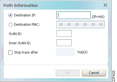
a.![]() In the Path Information dialog box, enter the required information. The contents depend on your launch point.
In the Path Information dialog box, enter the required information. The contents depend on your launch point.
|
|
|
|---|---|
Check this check box to enter a maximum of hops that Cisco PathTracer makes in its attempt to reach the destination |
Step 3![]() If you choose Start Here, navigate to the destination interface, port, or bridge, right-click it, and choose End Here. The Cisco PathTracer window is displayed showing the path or paths that were found.
If you choose Start Here, navigate to the destination interface, port, or bridge, right-click it, and choose End Here. The Cisco PathTracer window is displayed showing the path or paths that were found.
Step 4![]() To view additional details regarding the path traces, select one or more paths in the paths pane.
To view additional details regarding the path traces, select one or more paths in the paths pane.
Step 5![]() In the toolbar, click Cisco PathTracer.
In the toolbar, click Cisco PathTracer.
- If you select one or more paths in the paths pane, each selected path is displayed in its own window with the Layer 1, Layer 2, Layer 3, and Business Tag tabs.
- If you select nothing in the Paths pane, each path found is displayed in its own window with the Layer 1, Layer 2, Layer 3, and Business Tag tabs.
For more information about the end-to-end path and networking layer details, see Saving and Opening Cisco PathTracer Map Files.
Examples of Launching Cisco PathTracer
The following topics provide examples for launching Cisco PathTracer from different locations in the Vision client:
Using an Ethernet Flow Point
A network VLAN is required for you to start a path trace using an Ethernet flow point.
To launch a path trace from an Ethernet flow point:
Step 1![]() In the Vision client navigation pane or map pane, expand the required network VLAN.
In the Vision client navigation pane or map pane, expand the required network VLAN.
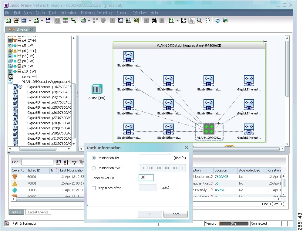
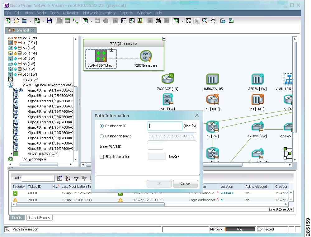
Step 2![]() In the VLAN, right-click the required Ethernet flow point and choose PathTracer > From Here to Destination. The Path Information dialog box is displayed as shown in Figure 13-2.
In the VLAN, right-click the required Ethernet flow point and choose PathTracer > From Here to Destination. The Path Information dialog box is displayed as shown in Figure 13-2.
Figure 13-2 Ethernet Flow Point Path Trace Launch Point
Step 3![]() Specify the destination.
Specify the destination.
Step 4![]() To limit the number of hops for the path trace, check the Stop trace after check box, and enter the maximum number of hops for the path trace.
To limit the number of hops for the path trace, check the Stop trace after check box, and enter the maximum number of hops for the path trace.
Step 5![]() Click OK. The Cisco PathTracer window is displayed with the resulting path trace.
Click OK. The Cisco PathTracer window is displayed with the resulting path trace.
Using an IP Interface
Both IPv4 and IPv6 addresses are supported as valid path trace sources and destinations as illustrated in the following procedure.
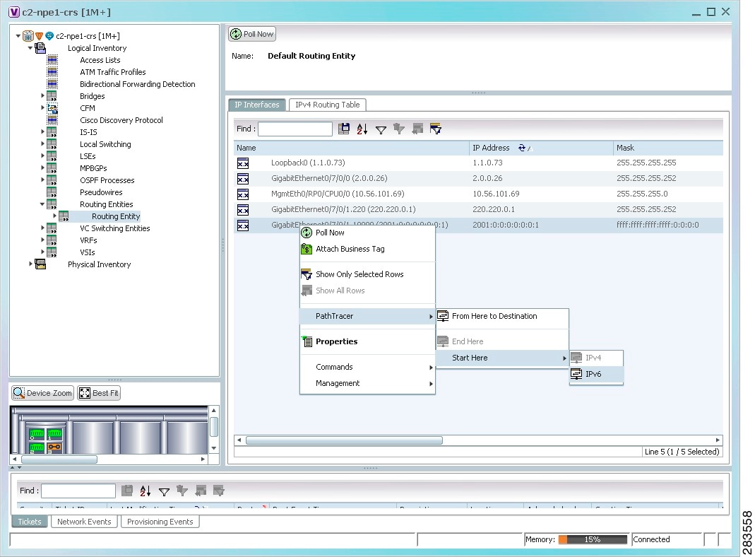
Step 1![]() In logical inventory, right-click the required IP interface (Logical Inventory > Routing Entities > Routing Entity > ip-interface).
In logical inventory, right-click the required IP interface (Logical Inventory > Routing Entities > Routing Entity > ip-interface).
The right-click menu displays IPv4 and IPv6 options. These options are enabled or dimmed, depending on whether the IP interface has an IPv4 address, an IPv6 address, or both IPv4 and IPv6 addresses. See Figure 13-3.
Figure 13-3 IP Interface Path Trace Launch Point - Right-Click Menu
Step 2![]() Choose PathTracer > From Here to Destination. The Path Information dialog box is displayed as shown in Figure 13-4.
Choose PathTracer > From Here to Destination. The Path Information dialog box is displayed as shown in Figure 13-4.
Figure 13-4 IP Interface Path Trace Launch Point - Path Information Dialog Box
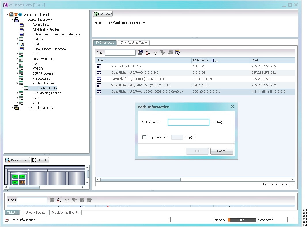
Step 3![]() In the Destination IP field, enter the IPv4 or IPv6 address.
In the Destination IP field, enter the IPv4 or IPv6 address.
Step 4![]() To limit the number of hops for the path trace, check the Stop trace after check box, and enter the maximum number of hops for the path trace.
To limit the number of hops for the path trace, check the Stop trace after check box, and enter the maximum number of hops for the path trace.
Using a VLAN Bridge
You can launch path traces from VLAN bridges. Additionally, MAC addresses in the VLAN bridge forwarding table can be path trace destinations.
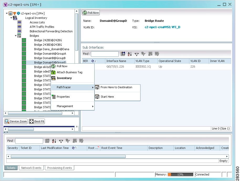
Step 1![]() In logical inventory, right-click the required bridge (Logical Inventory > Bridges > bridge) and choose one of the following options as shown in Figure 13-5:
In logical inventory, right-click the required bridge (Logical Inventory > Bridges > bridge) and choose one of the following options as shown in Figure 13-5:
Figure 13-5 VLAN Bridge Path Trace Launch Point
Step 2![]() If you choose From Here to Destination in Step 1
If you choose From Here to Destination in Step 1![]() , the Path Information dialog box is displayed. Specify the required destination.
, the Path Information dialog box is displayed. Specify the required destination.
Step 3![]() If you choose Start Here, navigate to the destination, right-click it, and choose End Here. Destination options include:
If you choose Start Here, navigate to the destination, right-click it, and choose End Here. Destination options include:
When a destination is selected, the system extracts the relevant IP address from this point and uses it as the destination.
Using an Ethernet Port
To launch a path trace from an Ethernet port:
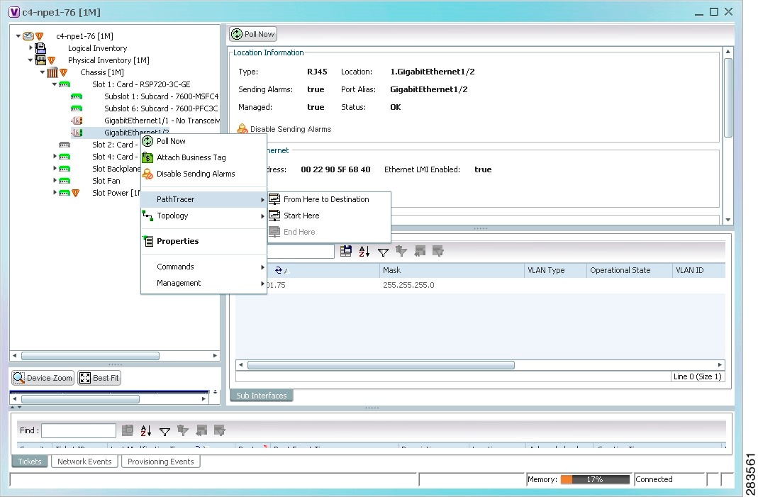
Step 1![]() In physical inventory, right-click the required port (Physical Inventory > Chassis > slot > subslot > port) and choose one of the following options as shown in Figure 13-6:
In physical inventory, right-click the required port (Physical Inventory > Chassis > slot > subslot > port) and choose one of the following options as shown in Figure 13-6:
Figure 13-6 Ethernet Port Path Trace Launch Point
Step 2![]() Depending on your choice in Step 1, specify the required destination information or select the path trace endpoint.
Depending on your choice in Step 1, specify the required destination information or select the path trace endpoint.
The Cisco PathTracer window appears, displaying the resulting path trace.
Using a Pseudowire
To launch a path trace from a network pseudowire endpoint:
Step 1![]() In the navigation pane or map pane, expand the required network pseudowire.
In the navigation pane or map pane, expand the required network pseudowire.
Step 2![]() Right-click the required pseudowire endpoint and choose PathTracer > From Here to Destination.
Right-click the required pseudowire endpoint and choose PathTracer > From Here to Destination.
The Path Information dialog box is displayed as shown in Figure 13-7.
Figure 13-7 Path Information Dialog Box for a Network Pseudowire
Step 3![]() Specify the destination.
Specify the destination.
Step 4![]() To limit the number of hops for the path trace, check the Stop trace after check box, and enter the maximum number of hops for the path trace.
To limit the number of hops for the path trace, check the Stop trace after check box, and enter the maximum number of hops for the path trace.
The Cisco PathTracer window appears, displaying the resulting path trace.
Using an MPLS-TP Tunnel Endpoint
To launch a path trace from an MPLS-TP tunnel endpoint:
Step 1![]() In the navigation pane or map pane, expand the required MPLS-TP tunnel.
In the navigation pane or map pane, expand the required MPLS-TP tunnel.
Step 2![]() Right-click the required MPLS-TP tunnel endpoint and choose PathTracer > From Here to Destination.
Right-click the required MPLS-TP tunnel endpoint and choose PathTracer > From Here to Destination.
The Path Information dialog box is displayed as shown in Figure 13-8.
Figure 13-8 MPLS-TP Tunnel Endpoint Path Trace Launch
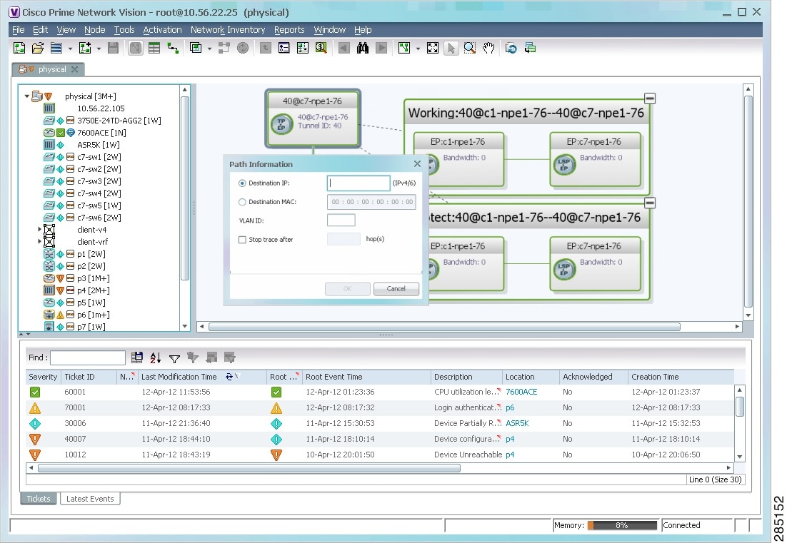
Step 3![]() Specify the destination.
Specify the destination.
Step 4![]() To limit the number of hops for the path trace, check the Stop trace after check box, and enter the maximum number of hops for the path trace.
To limit the number of hops for the path trace, check the Stop trace after check box, and enter the maximum number of hops for the path trace.
The Cisco PathTracer window appears, displaying the resulting path trace.
Viewing Path Traces
The Cisco PathTracer window displays all discovered paths for the specified source and destination of the path trace, including the devices and physical links. Form the window you can:
- View multiple paths for a selected source and destination either sequentially or simultaneously.
- View individual paths with networking layer details.
- Save a map with multiple paths to a file.
- Run Cisco PathTracer again, using the same trace or with a different limit number of hops.
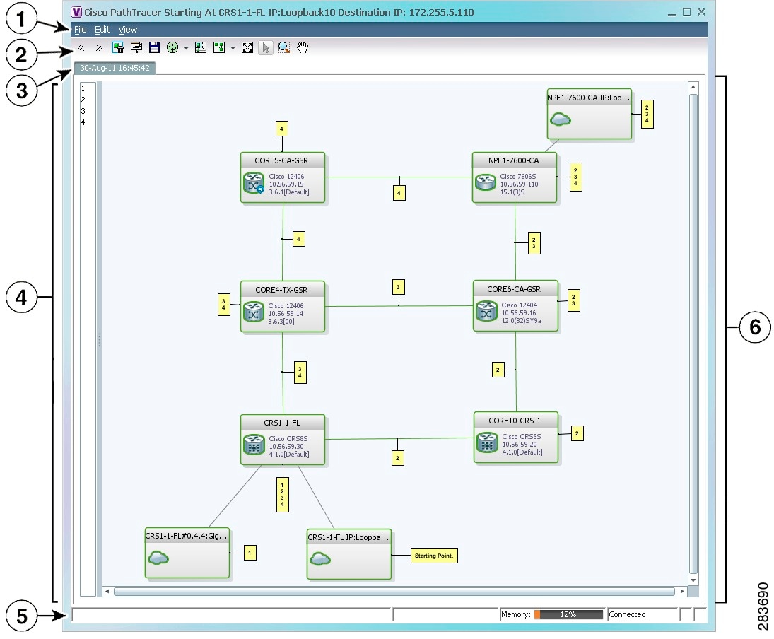
Figure 13-9 shows an example of the Cisco PathTracer window with a multiple-path trace.
Figure 13-9 Cisco PathTracer Window - Multiple-Path Trace
|
|
|
|
|---|---|---|
|
|
||
|
|
||
|
|
Displays the discovered path with a tab that displays the date and time when Prime Network started the path tracing process (snapshot time). New runs are represented in new tabs. To use a saved path in the same window, the source and destination must be the same. |
|
|
|
Lists all the paths discovered in the path trace (one path for each source and destination pair, identified by a number). If you launch a path trace with a specific hop count, the paths pane displays First n Hops where n is the number of hops specified. You can choose different paths in the path pane or by using the toolbar icons. Click Clear Path Selection to de-select a path. |
|
|
|
||
|
|
Displays the devices, links, and topological paths in path trace. All links and nodes are labeled with their relevant path numbers. The starting point is labeled with a Starting Point callout. All other edge points are displayed as clouds. The same coloring conventions that are used for links in the Prime Network content pane are used to display links in the Cisco PathTracer path trace pane. (See Links.) |
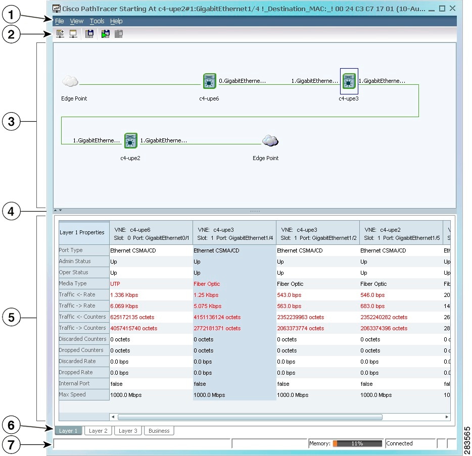
Click PathTracer from the toolbar to display the following information:
- Each NE’s relevant parameters for each interface on all layers along the path; for each layer, an indication of a mismatch between the parameters of the interfaces on both sides of a link; and traffic statistics along the path.
- Status and traffic information for all links along the path.
- View In and Out port properties.
If you select multiple paths, a separate window is opened for each path. Figure 13-10 shows an example of the Cisco PathTracer details window.
Figure 13-10 Cisco PathTracer Details Window
Cisco PathTracer Toolbar
Table 13-2 describes the options available in the Cisco PathTracer toolbar.
|
|
|
|---|---|

|
|

|
|

|
|

|
Opens the Cisco PathTracer details window. A map is displayed for the selected path, including network element details, links, and property information. For more information, see Saving and Opening Cisco PathTracer Map Files. |

|
Saves the current multiple-path trace to an XML file on your local system. For more information, see Saving and Opening Cisco PathTracer Map Files. |

|
Offers the following options for running Cisco PathTracer again for the same source and destination:
The new path trace map is displayed in the path trace pane. A new tab with the up-to-date (or refreshed) path map is created for each run, with each tab representing a run and the tab label indicating the snapshot time. |

|
Opens a window displaying a high level view of the path trace currently displayed in the path trace pane. |

|
Specifies how the elements are arranged in the path trace pane: circular, hierarchical, orthogonal, or symmetric. |

|
|

|
Activates the normal selection mode. The button toggles when selected or deselected. |

|
Activates the zoom selection mode, which enables you to select a specific area in the path to zoom in on by clicking and dragging. The button toggles when selected or deselected. |

|
Activates the pan mode, which enables you to move around in the path trace by clicking and dragging. The button toggles when selected or deselected. |
Saving and Opening Cisco PathTracer Map Files
Prime Network enables you to export multiple-path trace maps that are displayed in the Cisco PathTracer window to an XML file. You can view the data later to assess whether anything has changed.
Saving Cisco PathTracer Map Files
To save Cisco PathTracer map files:
Step 1![]() Open the Cisco PathTracer window as described in Launching Path Tracer.
Open the Cisco PathTracer window as described in Launching Path Tracer.
Step 2![]() Click Save MultiPath in the toolbar.
Click Save MultiPath in the toolbar.
Step 3![]() In the Save dialog box, navigate to the directory where you want to save the file and enter a name for the map file.
In the Save dialog box, navigate to the directory where you want to save the file and enter a name for the map file.
Step 4![]() Click Save. The map file is saved in the selected directory.
Click Save. The map file is saved in the selected directory.
Opening Cisco PathTracer Map Files
Prime Network enables you to open saved XML-formatted path-tracing maps.
The following conditions apply when working with multiple-path trace files:
- When you load a multiple-path trace file, Prime Network queries the file (not the network), and loads the persisted information.
- If you load a multiple-path trace file that does not contain the same start and end points, the map is automatically opened in a new Cisco PathTracer window.
To open Cisco PathTracer map files:
Step 1![]() In the Vision client, choose File > Load MultiPath from the main menu. The Open dialog box is displayed.
In the Vision client, choose File > Load MultiPath from the main menu. The Open dialog box is displayed.
Step 2![]() Navigate to the directory of the saved file and select the file.
Navigate to the directory of the saved file and select the file.
Step 3![]() Click Open. The previously saved map is displayed in the Cisco PathTracer window.
Click Open. The previously saved map is displayed in the Cisco PathTracer window.
Saving Cisco PathTracer Counter Values
Prime Network enables you to export, over a period of time, the counter values of the path displayed in the Cisco PathTracer window to a CSV file. The data can then be viewed later, as required.
Note![]() This topic applies to the Cisco PathTracer details window only.
This topic applies to the Cisco PathTracer details window only.
To save Cisco PathTracer counter values that are generated over a period of time:
Step 1![]() Open the Cisco PathTracer details window as described in Launching Path Tracer.
Open the Cisco PathTracer details window as described in Launching Path Tracer.
Step 2![]() Click Start Saving to File in the toolbar.
Click Start Saving to File in the toolbar.
Step 3![]() In the Export Table to File dialog box, navigate to the directory where you want to save the Cisco PathTracer counter values.
In the Export Table to File dialog box, navigate to the directory where you want to save the Cisco PathTracer counter values.
Step 4![]() In the File name field, enter a name for the file in which to save the counter values.
In the File name field, enter a name for the file in which to save the counter values.
Step 5![]() Click Save. Cisco PathTracer starts saving the counter values to the specified file.
Click Save. Cisco PathTracer starts saving the counter values to the specified file.
Step 6![]() To stop exporting counter values to the file, click Stop Saving to File in the toolbar.
To stop exporting counter values to the file, click Stop Saving to File in the toolbar.
Cisco PathTracer stops exporting the counter values to the file.
Rerunning a Path and Comparing Results
If you save a path to a file (see Saving and Opening Cisco PathTracer Map Files), you can use the file to rerun the same path automatically with the same source and destination. You can also compare the saved path to a newly run path to determine if the path has changed or to assess a problem.
Step 1![]() Load the required map file as described in Saving and Opening Cisco PathTracer Map Files. The Cisco PathTracer window is displayed with the previously saved map file.
Load the required map file as described in Saving and Opening Cisco PathTracer Map Files. The Cisco PathTracer window is displayed with the previously saved map file.
Step 2![]() Click Run Again in the toolbar.
Click Run Again in the toolbar.
The path trace runs automatically using the same source and destination as the loaded map file, and a new tab is displayed in the Cisco PathTracer window with the updated map. The tab displays the date and time when the path was rerun.
Step 3![]() Compare the previous map to the updated one by switching between the tabs in the Cisco PathTracer window.
Compare the previous map to the updated one by switching between the tabs in the Cisco PathTracer window.
Note ●![]() If you load a Cisco PathTracer map file that does not contain the same source and destination information as the map that is currently displayed in the window, the map is automatically opened in a new Cisco PathTracer window.
If you load a Cisco PathTracer map file that does not contain the same source and destination information as the map that is currently displayed in the window, the map is automatically opened in a new Cisco PathTracer window.
- If you load a Cisco PathTracer map file that contains the same source and destination information as a map that is currently displayed in the window, the map is loaded in a new tab in the same window.
Viewing Q-in-Q Path Information
The Q-in-Q (IEEE 802.1) tagging technology (also known as Dot1q tunneling) allows the nesting of another VLAN tag in a packet, in addition to an existing one. Either VLAN tag is considered an 802.1Q header.
Cisco PathTracer uses the VLAN tags of the Ethernet header and the port configuration to trace the path from one interface to another over the network. Among other things, you can:
- View a Layer 2 path across a LAN domain with all the VLAN tag information.
- For each network element, view the relevant parameters for each interface on all layers along the path.
Q-in-Q and Dot1q information is displayed in the Cisco PathTracer window when a path is traced over Ethernet ports with Dot1q and a Q-in-Q configuration.
As described in Launching Path Tracer, to view a specific path, you must specify an initial start point, such as an IP interface, and then an endpoint, such as a destination IP address.
To trace a Q-in-Q path, you start the path from any:
- Router or switch that is part of the Ethernet domain with Dot1q and Q-in-Q configurations.
- IP destination that can be reached from that point of the network.
After you select the endpoint, the Cisco PathTracer window is displayed. From this window, you can open the Cisco PathTracer details window, with the appropriate Q-in-Q information displayed in the Layer 2 tab.
The Layer 2 tab can display the following information specific to Q-in-Q and VLAN port configurations:
- VLAN Mode—The work mode for the interface: Unknown, Access, Trunk, or Dot1Q Tunnel. Trunk mode also refers to multiple tagging.
- Native VLAN ID—The VLAN identifier that is used to tag untagged traffic received on a trunked interface:
–![]() If VLAN tagging is enabled, the default native VLAN identifier is 1.
If VLAN tagging is enabled, the default native VLAN identifier is 1.
–![]() If VLAN tagging is disabled, the native VLAN identifier is 0 (zero) or “no VLAN ID.”
If VLAN tagging is disabled, the native VLAN identifier is 0 (zero) or “no VLAN ID.”
Viewing L2TP Path Information
Cisco PathTracer uses VC ID encapsulation information to trace the path from one tunnel interface to another over the network. The Cisco PathTracer tool enables you to:
- View a path for the defined Layer 2 Tunneling Protocol (L2TP) session across the network.
- For each network element, view the relevant parameters for each interface on all layers along the path.
The Layer 3 tab displays the peer name for L2TP tunnels.
Table 13-3 describes the information that is displayed in the Layer 2 tab for L2TP tunnels.
Using Cisco PathTracer in MPLS Networks
You can open and view Cisco PathTracer information between service endpoints, such as an IP interface that is attached to the VRF over an MPLS network. The LSP in the MPLS network is found according to the cross-connect table of each router.
Note![]() An LSP can be traced and displayed by Cisco PathTracer as part of an end-to-end tracing of a service; for example, when viewing a path between one CE device and another. Cisco PathTracer traces the path that goes over circuits or VLANs in the access networks. It also traces the LSPs between the VRFs going through all intermediate devices such as CE devices, aggregation switches, PE routers, and core routers.
An LSP can be traced and displayed by Cisco PathTracer as part of an end-to-end tracing of a service; for example, when viewing a path between one CE device and another. Cisco PathTracer traces the path that goes over circuits or VLANs in the access networks. It also traces the LSPs between the VRFs going through all intermediate devices such as CE devices, aggregation switches, PE routers, and core routers.
To view a specific path, you must specify an initial starting point, such as an IP interface; specifying a destination IP address is optional. If the traced path (for example, a VC or VLAN) ends in a router, Cisco PathTracer finds the next hop according to the destination IP address. If you select an endpoint, Cisco PathTracer extracts the relevant IP address from this point and uses it as the destination.
The following topics provide more information on using Cisco PathTracer in MPLS networks:
- Cisco PathTracer MPLS Start and Endpoints
- Using Cisco PathTracer for CSC Configurations
- Using Cisco PathTracer for Layer 3 VPNs
- Using Cisco PathTracer for Layer 2 VPNs
- Using Cisco PathTracer for MPLS TE Tunnels
Cisco PathTracer MPLS Start and Endpoints
You can open Cisco PathTracer by right-clicking a starting point and entering the required destination IP address. Table 13-4 lists the Cisco PathTracer starting points.
If you choose the Start Here option, Table 13-5 lists the endpoints that can be selected as path destinations.
|
|
|
|
|---|---|---|
The Cisco PathTracer window is displayed. From this window you can open the Cisco PathTracer details window with the VPN information displayed in the Layer 2 and Layer 3 tabs.
Note![]() If multiple paths are selected in the paths pane, or if nothing is selected in the paths pane, all available paths are opened automatically, and each is displayed in a separate Cisco PathTracer window.
If multiple paths are selected in the paths pane, or if nothing is selected in the paths pane, all available paths are opened automatically, and each is displayed in a separate Cisco PathTracer window.
Using Cisco PathTracer for CSC Configurations
Cisco PathTracer traces a CSC flow from the customer CE through the customer carrier VPN, across the customer backbone carrier VPN, back to the customer carrier VPN, and to the destination CE.
To launch a path trace for a CSC configuration:
Step 1![]() In a map, double-click the required CE device.
In a map, double-click the required CE device.
Step 2![]() In the Inventory window, choose Logical Inventory > Routing Entities > Routing Entity.
In the Inventory window, choose Logical Inventory > Routing Entities > Routing Entity.
Step 3![]() In the IP Interfaces table, right-click the required interface and choose PathTracer > Start Here > IPvn where IPvn represents IPv4 or IPv6.
In the IP Interfaces table, right-click the required interface and choose PathTracer > Start Here > IPvn where IPvn represents IPv4 or IPv6.
Step 4![]() Navigate to the destination CE device and double-click it.
Navigate to the destination CE device and double-click it.
Step 5![]() In the Inventory window, choose Logical Inventory > Routing Entities > Routing Entity.
In the Inventory window, choose Logical Inventory > Routing Entities > Routing Entity.
Step 6![]() In the IP Interfaces table, right-click the required interface and choose PathTracer > End Here.
In the IP Interfaces table, right-click the required interface and choose PathTracer > End Here.
The path trace is displayed in the Cisco PathTracer window.
Step 7![]() To view the detailed pane, click Cisco PathTracer in the toolbar.
To view the detailed pane, click Cisco PathTracer in the toolbar.
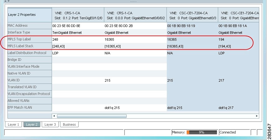
The Layer 2 tab displays a single outer label and two inner labels for each interface, reflecting the CSC configuration. (See Figure 13-11.)
Figure 13-11 CSC Configuration Path Trace
Using Cisco PathTracer for Layer 3 VPNs
Cisco PathTracer uses VRF routing and label switching information to trace the path from one VRF interface to another. If you choose a launch point and destination from the right-click menu, you can open the Cisco PathTracer for Layer 3 VPNs. The Cisco PathTracer window shows the VPN topology map. From this window, you can open the Cisco PathTracer details window with the appropriate VPN information displayed in the Layer 2 and Layer 3 tabs.
For Layer 3 path information, Prime Network uses VRF routing and label switching information to trace the path from one VRF interface to another. Layer 3 path trace information is displayed in the Cisco PathTracer window when the path goes over connections and ends in VRFs.
If a VRF table includes more than one path toward a destination, Cisco PathTracer shows all paths.
To view Layer 3 path information, choose the Layer 3 tab and choose Show All from the View menu. The path information is displayed in the active tab.
The table displays the Layer 3 VPN information on the device that has a VRF. The following Layer 3 properties displayed in the Layer 3 tab relate specifically to VPNs:
- Name—The name of the site. For example, ATM4/0.100(10.0.0.1) is a combination of the interface name and IP address used to reach the site. Each site belongs to a particular VPN, so the address must be unique within the VPN.
- IP Address—The IP address of the interface.
- Mask—The mask of the specific network.
- State—The state of the interface (up or down).
- VRF Name—The name of the VRF.
Cisco PathTracer does not display or trace EXP bits for Layer 3 VPNs that use policy-based tunnel selection (PBTS).
Using Cisco PathTracer for Layer 2 VPNs
Cisco PathTracer uses VC ID and label switching information to trace the path from one tunnel interface to another over the MPLS network.
Cisco PathTracer also covers end-to-end Layer 2 VPN service paths from one CE router to another. The path goes over circuits (such as a VC) or VLANs in access networks and over LSP between the Layer 2 tunnel edge.
The Cisco PathTracer window shows the VPN topology map for the relevant devices and links. From this window, you can open the Cisco PathTracer details window with the appropriate VPN information displayed in the Layer 2 and Layer 3 tabs.
For Layer 2 path information, Cisco PathTracer uses VC ID, AGI, SAII, TAII, and label switching information to trace the path from one tunnel interface to another. Layer 2 path trace information is displayed in the Cisco PathTracer window when the path goes over pseudowire tunnels.
To view Layer 2 path information, choose the Layer 2 tab and then View > Show All. The path information is displayed in the active tab.
Table 13-6 describes the Layer 2 properties that can be displayed in the Layer 2 tab specifically for VPNs.
Using Cisco PathTracer for MPLS TE Tunnels
Cisco PathTracer uses label switching information to trace the end-to-end path of a TE tunnel path from one PE router to another.
Using MPLS TE technology, Cisco PathTracer enables you to:
–![]() The relevant parameters for each interface on all layers along the path.
The relevant parameters for each interface on all layers along the path.
–![]() The path for the defined MPLS TE-LSP across the network.
The path for the defined MPLS TE-LSP across the network.
The Cisco PathTracer window is displayed showing the MPLS TE tunnel topology map. From this window, you can open the Cisco PathTracer details window with the appropriate MPLS TE tunnel information displayed in the Layer 2 tab.
Note![]() Cisco PathTracer does not display or trace EXP bits for Layer 3 VPNs that use PBTS.
Cisco PathTracer does not display or trace EXP bits for Layer 3 VPNs that use PBTS.
Layer 2 and Layer 3 path trace information is displayed in the Cisco PathTracer details window when a path is traced over MPLS TE tunnels. To view Layer 2 path information, choose the Layer 2 tab and then View > Show All. The path information is displayed in the active tab.
Table 13-7 describes the Layer 2 properties that can be displayed in the Layer 2 tab specifically for MPLS TE tunnels.
|
|
|
|---|---|
MPLS TE data set in an MPLS interface, primarily bandwidth allocation levels and signaling protocol. |
|
Operational status of the tunnel: Up or Down. If this value is Up, the Tunnel Admin Status must also be Up. See Tunnel Admin Status properties for additional information. |
|
Administrative status of the tunnel (Up or Down) with the following caveats:
|
|
Whether or not destinations behind the tunnel are routed through the tunnel: Enabled or disabled. |
|
TE tunnel MPLS label distinguishing the LSP selection in the adjacent device. |
|
Tunnel affinity bits that should be compared to the link attribute bits. |
 Feedback