- Overview of Prime Network GUI clients
- Setting Up the Prime Network Clients
- Setting Up Change and Configuration Management
- Setting Up Vision Client Maps
- Setting Up Native Reports
- Setting Up Fault Management and the Events Client Default Settings
- Viewing Devices, Links, and Services in Maps
- Drilling Down into an NE’s Physical and Logical Inventories and Changing Basic NE Properties
- Manage Device Configurations and Software Images
- How Prime Network Handles Incoming Events
- Managing Tickets with the Vision Client
- Viewing All Event Types in Prime Network
- Cisco Path Tracer
- Managing IP Address Pools
- Monitoring AAA Configurations
- Managing DWDM Networks
- Managing MPLS Networks
- Managing Carrier Ethernet Configurations
- Managing Ethernet Networks Using Operations, Administration, and Maintenance Tools
- Monitoring Carrier Grade NAT Configurations
- Monitoring Quality of Service
- Managing IP Service Level Agreement (IP SLA) Configurations
- Monitoring IP and MPLS Multicast Configurations
- Managing Session Border Controllers
- Monitoring BNG Configurations
- Managing Mobile Transport Over Pseudowire (MToP) Networks
- Managing Mobile Networks
- Managing Data Center Networks
- Monitoring Cable Technologies
- Monitoring ADSL2+ and VDSL2 Technologies
- Monitoring Quantum Virtualized Packet Core
- VSS Redundancy System
- Icon Reference
- Permissions Required to Perform Tasks Using the Prime Network Clients
- Correlation Examples
- Managing certificates
Cisco Prime Network User Guide, 5.1
Bias-Free Language
The documentation set for this product strives to use bias-free language. For the purposes of this documentation set, bias-free is defined as language that does not imply discrimination based on age, disability, gender, racial identity, ethnic identity, sexual orientation, socioeconomic status, and intersectionality. Exceptions may be present in the documentation due to language that is hardcoded in the user interfaces of the product software, language used based on RFP documentation, or language that is used by a referenced third-party product. Learn more about how Cisco is using Inclusive Language.
- Updated:
- July 19, 2017
Chapter: Managing MPLS Networks
- Viewing IPv6 Information (6VPE)
- Working with MPLS-TP Tunnels
- Viewing VPNs
- Managing VPNs
- Working with VPN Overlays
- Monitoring MPLS Services
- Viewing VPN Properties
- Viewing Site Properties
- Viewing VRF Properties
- Viewing VRF Egress and Ingress Adjacents
- Viewing Routing Entities
- Viewing Label Switched Entity Properties
- Multicast Label Switching (mLADP)
- Viewing BGP Neighbor Service Alarm with VRF Name
- Viewing MP-BGP Information
- Viewing 6rd Tunnel Properties
- Viewing BFD Session Properties
- BFD Single-Hop Authentication
- Viewing Cross-VRF Routing Entries
- Viewing Pseudowire End-to-End Emulation Tunnels
- Viewing MPLS TE Tunnel Information
- Configuring VRFs
- Configuring IP Interfaces
- Auto-IP in PN
- Configuring Auto-IP
- Configuring MPLS-TP
- Configuring MPLS-TE
- Configuring MPLS
- Configuring RSVP
- Configuring BGP
- Configuring VRRP
- Configuring Bundle Ethernet
- Viewing MPLS LDP, Static Information
- Working with FEC 129-based Pseudowire
- FEC 129-based Pseudowire
- Viewing FEC 129-based Pseudowire from Logical Inventory
- Viewing FEC 129 links from Topology View
- Viewing FEC 129 Type II-based Pseudowire Tunnel from Pseudowire Map View
- Viewing FEC 129 Type II-based Pseudowire Tunnels from Virtual Connection Map View
- Viewing FEC 129 Type I-based Pseudowire Tunnel from VPLS Map view
- Viewing FEC 129 Type I-based Pseudowire Tunnels from Virtual Connection Map View
Managing MPLS Networks
The following topics describe how to view and manage aspects of Multiprotocol Label Switching (MPLS) services using the Vision client, including the MPLS service view, business configuration, and maps. The topics also describe the device inventory specific to MPLS VPNs, including routing entities, label switched entities (LSEs), BGP Neighbors, Multiprotocol BGP (MP-BGP), VRF instances, pseudowires, and TE tunnels. If you cannot perform an operation that is described in these topics, you may not have sufficient permissions; see Permissions for Managing MPLS Services.
- Working with MPLS-TP Tunnels
- Viewing VPNs
- Managing VPNs
- Working with VPN Overlays
- Monitoring MPLS Services
- Configuring VRFs
- Configuring IP Interfaces
- Auto-IP in PN
- Configuring Auto-IP
- Configuring MPLS-TP
- Configuring MPLS-TE
- Configuring MPLS
- Configuring RSVP
- Configuring BGP
- Configuring VRRP
- Configuring Bundle Ethernet
- Working with FEC 129-based Pseudowire
Viewing IPv6 Information (6VPE)
Prime Network supports IPv6 for:
- Gateways, clients, and units using IPv6.
- Communications between VNEs and devices in IPv6 environments, whether the device management IP address is IPv4 or IPv6.
- Polling and notification using the following protocols over IPv6:
–![]() SNMP v1, SNMPv2c, and SNMPv3
SNMP v1, SNMPv2c, and SNMPv3
–![]() XML (for Cisco IOS XR devices)
XML (for Cisco IOS XR devices)
–![]() HTTP (for Cisco UCS and VMware vCenter devices)
HTTP (for Cisco UCS and VMware vCenter devices)
- All reports with devices that use IPv6 addresses.
- Fault management, including event processing and service alarm generation.
Prime Network supports correlation and path tracing for:
IPv6 VPN over MPLS, also known as 6VPE, uses the existing MPLS IPv4 core infrastructure for IPv6 transport to enable IPv6 sites to communicate over an MPLS IPv4 core network using MPLS label switch paths (LSPs). 6VPE relies on MP-BGP extensions in the IPv4 network configuration on the PE router to exchange IPv6 reachability information. Edge routers are configured to be dual-stacks running both IPv4 and IPv6, and use the IPv4-mapped IPv6 address for IPv6 prefix reachability exchange.
In 6VPE environments, Prime Network supports:
- Modeling of OSPFv3 routes between PE and CE devices.
- IPv6 addresses for BGP Neighbours for MP-BGP.
- Correlation and path tracing.
The Vision client displays IPv6 addresses when they are configured on PE and CE routers in the IP interface table. IPv6 addresses are:
- Displayed in the Vision client map pane for IPv6 links.
- Displayed in logical and physical inventory for routing and interface information, including IP, PPP, and High-Level Data Link Control (HDLC).
- Used in Cisco PathTracer to trace paths and present path trace results.
Table 17-1 describes where IPv6 information appears in logical and physical inventory.
|
|
|
|---|---|
|
|
|
The Tunnel Edges table displays IPv6 addresses and the IPv6 prefixes that are used to translate IPv4 addresses to IPv6 addresses. For more information, see Viewing 6rd Tunnel Properties. |
|
Carrier Grade NAT service types include 6rd and XLAT. For more information, see Viewing Carrier Grade NAT Properties in Logical Inventory. |
|
The IP Address field supports IPv6 addresses. For more information, see Viewing MPLS Pseudowire Over GRE Properties. |
|
For more information, see Viewing IS-IS Properties. |
|
For information, see Viewing MP-BGP Information. |
|
IPv6 addresses are displayed for OSPF Neighbour interface addresses, OSPF interface internet addresses, OSPF Neighbour properties window, and OSPF interface properties window. For more information, see Viewing OSPF Properties. |
|
For more information, see Viewing Routing Entities. |
|
IPv6 addresses appear in the IPv6 tab, Sites tab, VRF Properties window, and IP Interface Properties window. For more information, see Viewing VRF Properties. |
|
|
|
|
IPv6 addresses appear in the Subinterfaces tab and interface properties popup window. |
|
The IP addresses that appear depend on whether the interface has only IPv4 addresses, only IPv6 addresses, or both IPv4 and IPv6 addresses, as shown in Table 17-2 .
|
|
|
|
|---|---|---|
Note the following when working with IPv6 addresses:
- MPLS label switching entries and Label Switching Entities (LSEs) do not display IPv6 addresses. However, the Neighbour Discovery Protocol (NDP) table does display IPv6 addresses.
- Prime Network supports all the textual presentations of address prefixes. However, the Vision client displays both the IP address and the subnet prefix, for example:

Note![]() Interfaces or subinterfaces that do not have IP addresses are not discovered and therefore are not shown in the Vision client.
Interfaces or subinterfaces that do not have IP addresses are not discovered and therefore are not shown in the Vision client.
Figure 17-1 shows a port inventory view of a port with IPv4 and IPv6 addresses. In this example, one IPv4 address and multiple IPv6 addresses are provisioned on the interface.
- The primary IPv4 address appears in the interface table and properties window. If secondary IPv4 addresses were provisioned on the interface, they would appear in the properties window.
- IPv6 addresses provisioned on the interface appear in the properties window and Sub Interfaces tab.
Figure 17-1 Port with IPv4 and IPv6 Addresses
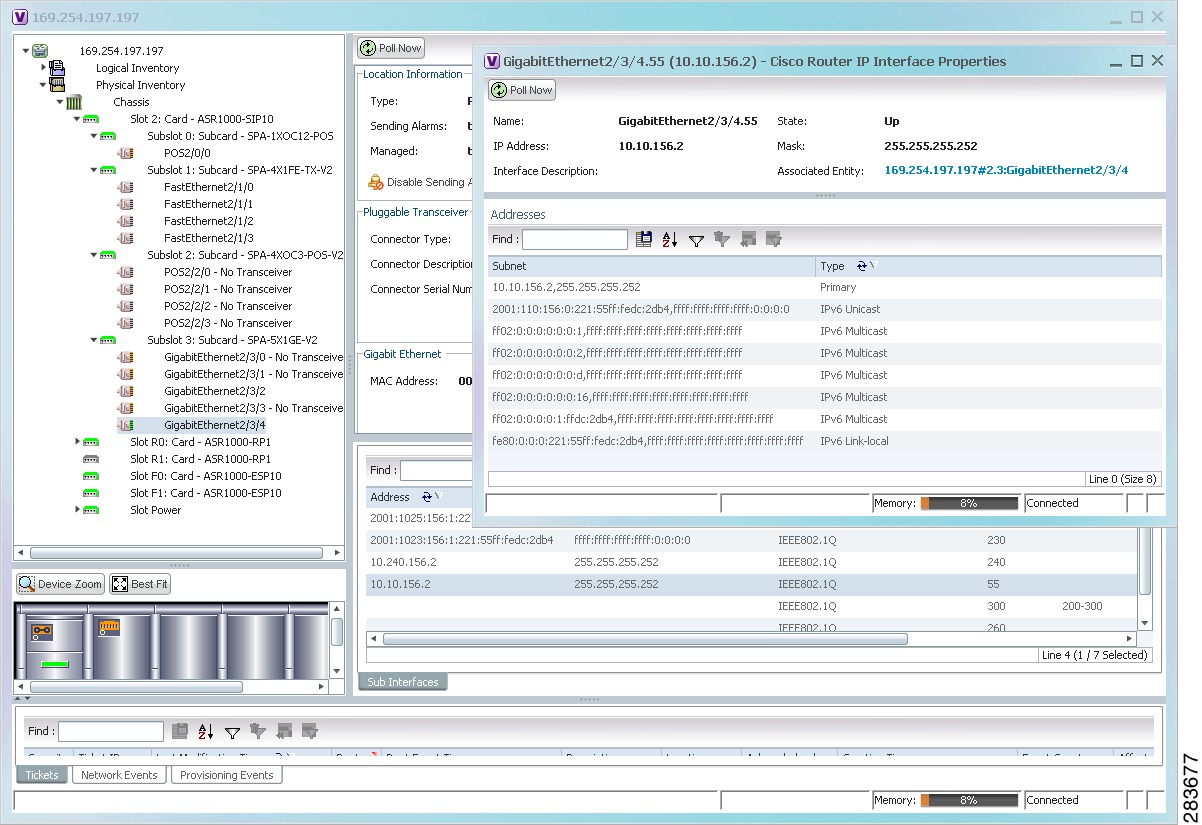
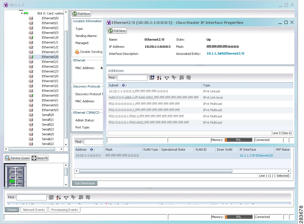
Figure 17-2 shows a port with only IPv6 addresses provisioned. In this example, the lowest IPv6 address is shown in the subinterface table, and all IPv6 addresses are shown in the interface properties window.
Figure 17-2 Port with IPv6 Addresses
Working with MPLS-TP Tunnels
MPLS-Transport Profile (MPLS-TP) is considered to be the next generation transport for those using SONET/SDH TDM technologies as they migrate to packet-switching technology. Although still under definition by the IETF, MPLS-TP provides:
- Predetermined and long-lived connections.
- Emphasis on manageability and deterministic behavior.
- Fast fault detection and recovery.
- Inband OAM.
- Manually provisioned MPLS-TP LSPs.
- Reserved bandwidth for static MPLS-TP LSPs.
- One-to-one path protection for MPLS-TP LSPs.
- Working/Protected LSP switchover.
- Continuity Check (CC), Proactive Continuity Verification (CV), and Remote Defect Indication (RDI) based on BFD.
- New fault OAM functions resulting from the MPLS-TP standardization effort.
Prime Network automatically discovers network MPLS-TP tunnels from end to end, including LSPs, tunnel endpoints, and bandwidth. Network LSPs contain LSP endpoints and midpoints and are identified as working or protected.
Prime Network links the MPLS-TP tunnel components appropriately, provides a visual representation in Vision client maps, and displays the properties in logical inventory.
Prime Network employs warm start technology when rebooting. That is, when rebooting, Prime Network compares existing MPLS-TP tunnel information to topology changes that occur while Prime Network is down and updates MPLS-TP tunnel accordingly when Prime Network returns to operation.
The following options are available for working with MPLS-TP tunnels in the Vision client:
- Adding an MPLS-TP Tunnel
- Viewing MPLS-TP Tunnel Properties
- Viewing LSPs Configured on an Ethernet Link
- Viewing LSP Endpoint Redundancy Service Properties
- Applying an MPLS-TP Tunnel Overlay
- Viewing BFD Session Properties.
Adding an MPLS-TP Tunnel
Prime Network automatically discovers MPLS-TP tunnels, endpoints, and midpoints and enables you to add MPLP-TP tunnels to maps.
To add an MPLS-TP tunnel to a map:
Step 1![]() In the Vision client, display the map to which you want to add the MPLS-TP tunnel.
In the Vision client, display the map to which you want to add the MPLS-TP tunnel.
Step 2![]() Do either of the following:
Do either of the following:
The Add MPLS-TP Tunnel dialog box is displayed.
Step 3![]() Do either of the following:
Do either of the following:
Step 4![]() Select the MPLS-TP tunnel that you want to add to the map.
Select the MPLS-TP tunnel that you want to add to the map.
The MPLS-TP tunnel is added to the map and to the navigation pane.
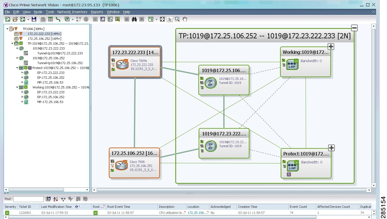
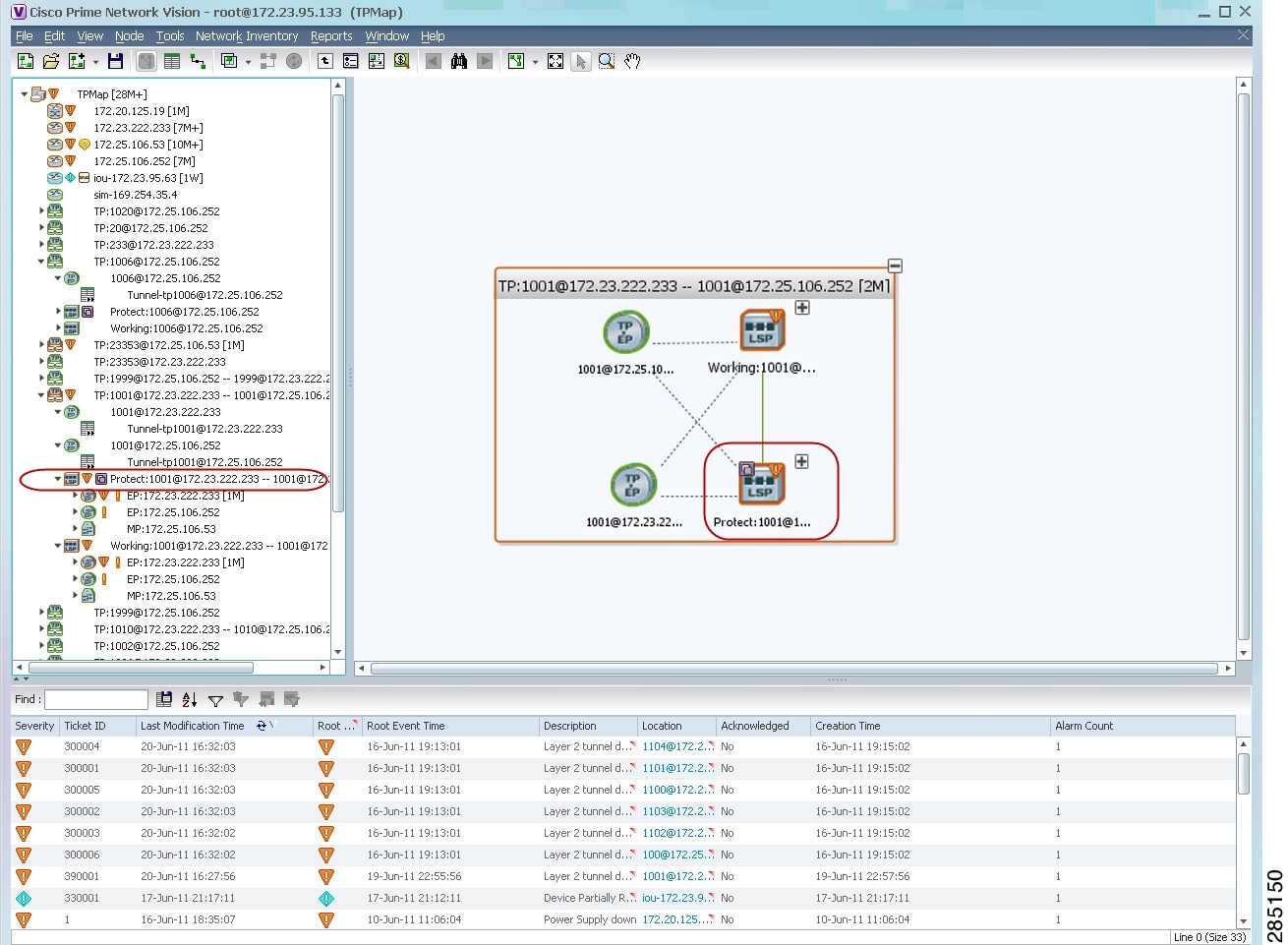
In Figure 17-3:
- The devices are on the left side of the map, and the MPLS-TP tunnel is displayed in a thumbnail on the right.
- The devices are connected to each other and to the MPLS-TP tunnel via tunnels.
- Physical links connect the devices to the Working and Protected LSPs.
- A redundancy service badge is displayed next to the Protected LSP in the navigation and map panes.
- In the thumbnail:
–![]() The tunnel endpoints are connected to each other via a tunnel.
The tunnel endpoints are connected to each other via a tunnel.
–![]() A physical link connects the Working and Protected LSPs.
A physical link connects the Working and Protected LSPs.
–![]() Business links connect the Working and Protected LSPs to each endpoint.
Business links connect the Working and Protected LSPs to each endpoint.
Figure 17-3 MPLS-TP Tunnel in Vision Map
If an LSP is in lockout state, it is displayed with the lock badge ( ).
).
By expanding all aggregations in the MPLS-TP tunnel (see Figure 17-4), you can see components and links in the MPLS-TP tunnel, including:
Figure 17-4 MPLS-TP Tunnel Expanded
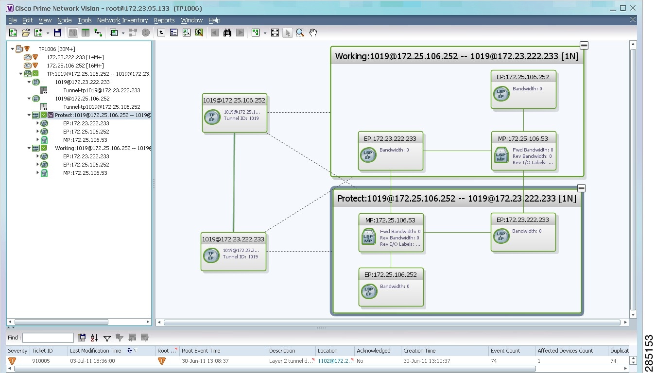
If an LSP is configured for redundancy service, a redundancy service badge is applied to the secondary (backup) LSP in the navigation and map panes in the navigation and map panes.
For more information about LSP redundancy service, see Viewing LSP Endpoint Redundancy Service Properties.
Viewing MPLS-TP Tunnel Properties
Prime Network discovers and displays MPLS-TP attributes in the MPLS-TP branch in logical inventory as described in this topic.
Additional information about MPLS-TP tunnel properties are available in the following branches:
- Routing Entities—See Viewing Routing Entities.
- LSEs—See Viewing Label Switched Entity Properties.
- Pseudowires— See Viewing Pseudowire End-to-End Emulation Tunnels.
To view MPLS-TP tunnel properties:
Step 1![]() Right-click the required device in the Vision client and choose Inventory.
Right-click the required device in the Vision client and choose Inventory.
Step 2![]() In the logical inventory window, choose Logical Inventory > MPLS-TP > MPLS-TP Global.
In the logical inventory window, choose Logical Inventory > MPLS-TP > MPLS-TP Global.
The routing information is displayed as shown in Figure 17-5.
Figure 17-5 MPLS-TP Tunnel Properties in Logical Inventory
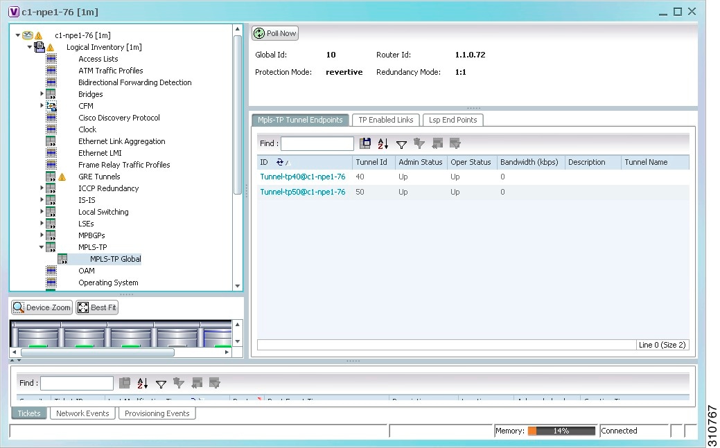
Table 17-3 describes the information that is available for MPLS-TP tunnels. The information that is displayed depends on the configuration.
Step 3![]() To view additional MPLS-TP tunnel endpoint properties, double-click the required entry in the MPLS-TP Tunnel Endpoints table.
To view additional MPLS-TP tunnel endpoint properties, double-click the required entry in the MPLS-TP Tunnel Endpoints table.
The MPLS-TP Tunnel Properties window is displayed as shown in Figure 17-6.
Figure 17-6 MPLS-TP Tunnel Properties Window
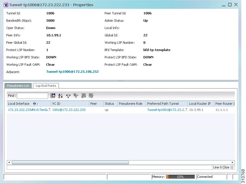
Table 17-4 describes the information available in the top portion of the MPLS-TP Tunnel Properties window. For information about the tabs that are displayed, see Table 17-3 .
Viewing LSPs Configured on an Ethernet Link
A single Ethernet link can support a number of LSPs. The Vision client enables you to view all LSPs on a single Ethernet link and to identify the source and destination labels.
To view LSPs configured on an Ethernet link:
Step 1![]() In the map view, right-click the required link and choose Properties.
In the map view, right-click the required link and choose Properties.
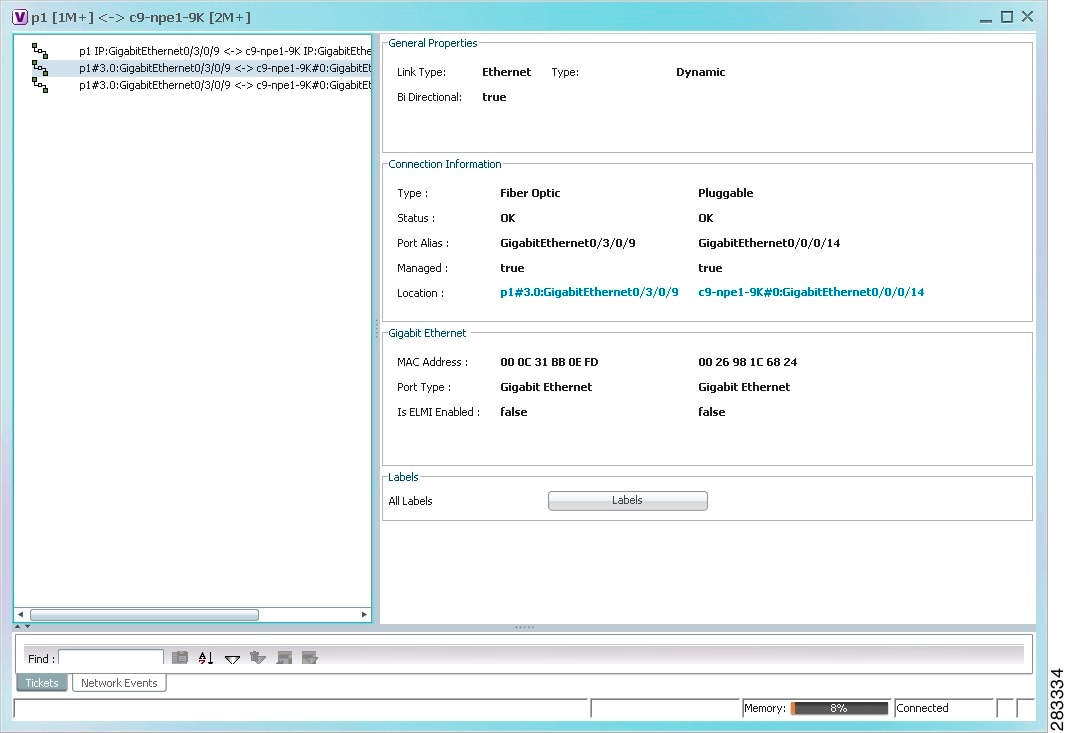
Step 2![]() In the link properties window, choose the required Ethernet link.
In the link properties window, choose the required Ethernet link.
The link properties window refreshes and displays the Labels button as shown in Figure 17-7.
Figure 17-7 Link Properties Window with All Labels Button
The All Labels window is displayed as shown in Figure 17-8 with the LSP sources and destinations.
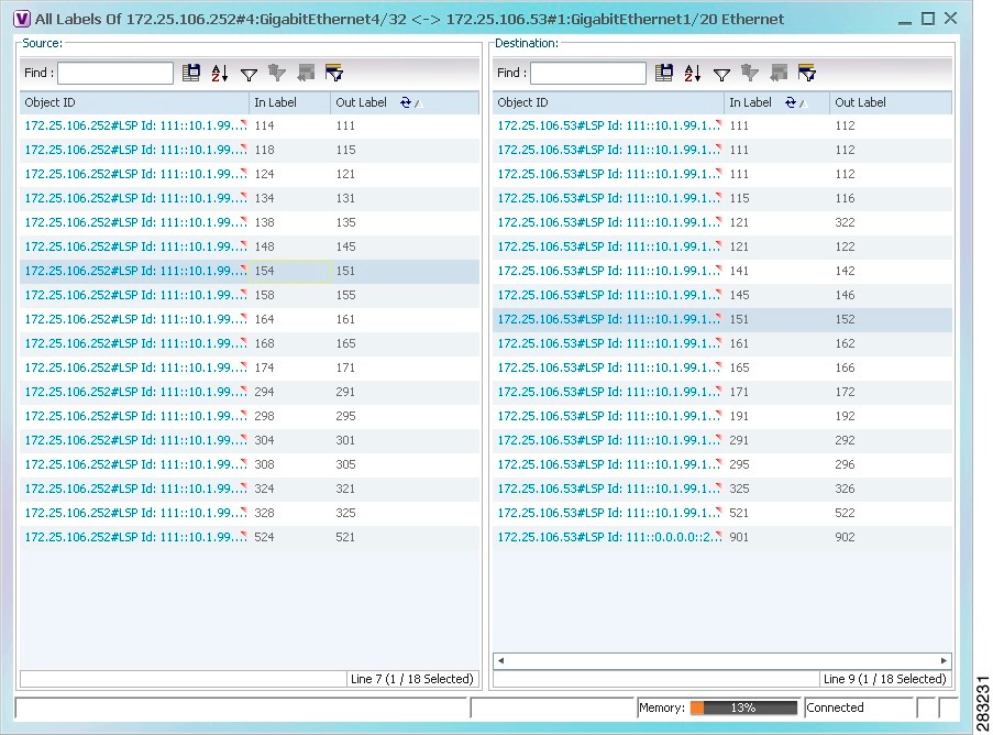
Step 4![]() To identify a specific path, click an outgoing label in the Source table. The corresponding in label is selected in the Destination table.
To identify a specific path, click an outgoing label in the Source table. The corresponding in label is selected in the Destination table.
Viewing MPLS-TE and P2MP-MPLS-TE links in a map
Using the link filter available in Prime Network, you can view only the MPLS-TE and P2MP-MPLS-TE links in a map.
Note![]() The MPLS Point-to-Multipoint Traffic Engineering (P2MP TE) feature enables you to forward Multiprotocol Label Switching (MPLS) traffic from one source to multiple destinations.
The MPLS Point-to-Multipoint Traffic Engineering (P2MP TE) feature enables you to forward Multiprotocol Label Switching (MPLS) traffic from one source to multiple destinations.
To view the MPLS-TE and P2MP-MPLS-TE links in a map:
Step 2![]() Click the Link filter icon in the navigation menu.
Click the Link filter icon in the navigation menu.
Step 3![]() In the Link Filter window, select the MPLS-TE and P2MP MPLS-TE check boxes.
In the Link Filter window, select the MPLS-TE and P2MP MPLS-TE check boxes.
Step 4![]() Click OK. The map refreshes and displays only the MPLS-TE and P2MP MPLS-TE links.
Click OK. The map refreshes and displays only the MPLS-TE and P2MP MPLS-TE links.
Step 5![]() Right-click on the link and choose the Properties option.
Right-click on the link and choose the Properties option.
Step 6![]() In the Link Properties window, the type of link is displayed in the Link Type field, which can be either MPLS-TE and P2MP MPLS-TE based on the link that you have selected. Additional details about the link such as the MPLS TE tunnel, operational status of the tunnel, TE tunnel type are displayed in the Label Switching section. For more information about the Link Properties window, see Viewing LSPs Configured on an Ethernet Link.
In the Link Properties window, the type of link is displayed in the Link Type field, which can be either MPLS-TE and P2MP MPLS-TE based on the link that you have selected. Additional details about the link such as the MPLS TE tunnel, operational status of the tunnel, TE tunnel type are displayed in the Label Switching section. For more information about the Link Properties window, see Viewing LSPs Configured on an Ethernet Link.
Viewing LSP Endpoint Redundancy Service Properties
If an LSP endpoint in an MPLS-TP tunnel is configured for redundancy service, a redundancy service badge is applied to the secondary (backup) LSP endpoint in the navigation and map panes in the Vision client. Additional redundancy service details are provided in the LSP endpoint properties window and the inventory window for the element on which the MPLS-TP tunnel is configured.
To view LSP endpoint redundancy service properties:
Step 1![]() To determine if an LSP endpoint on an MPLS-TP tunnel is configured for redundancy service, expand the required MPLS-TP tunnel in the navigation or map pane.
To determine if an LSP endpoint on an MPLS-TP tunnel is configured for redundancy service, expand the required MPLS-TP tunnel in the navigation or map pane.
If the LSP endpoint is configured for redundancy service, the redundancy service badge is displayed in the navigation and map panes as shown in Figure 17-9.
Figure 17-9 LSP Endpoint with Redundancy Service Badge
Step 2![]() To view properties for the LSP endpoint, navigate to and right-click the required endpoint in the map or navigation pane, and choose Properties.
To view properties for the LSP endpoint, navigate to and right-click the required endpoint in the map or navigation pane, and choose Properties.
The LSP endpoint properties window is displayed as shown in Figure 17-10.
Figure 17-10 LSP Endpoint Properties Window
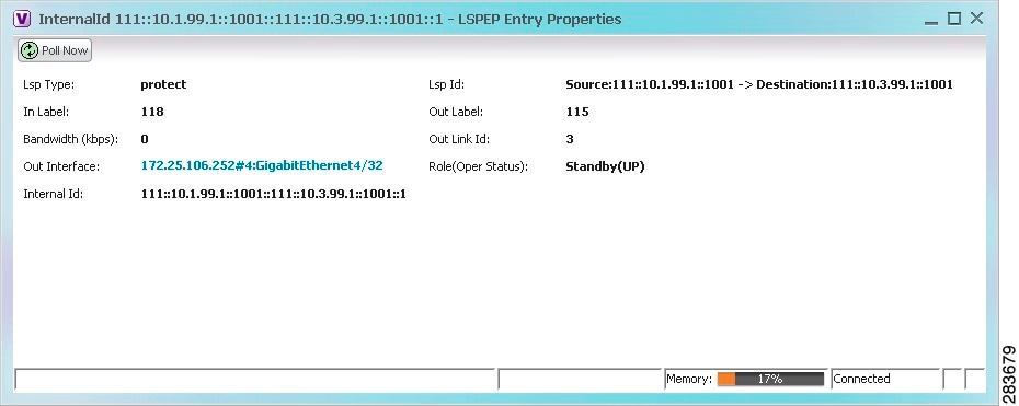
Table 17-5 describes the information displayed in the LSP Endpoint Properties window.
Step 3![]() To view LSP endpoint redundancy status in inventory, double-click the element on which the MPLS-TP tunnel is configured.
To view LSP endpoint redundancy status in inventory, double-click the element on which the MPLS-TP tunnel is configured.
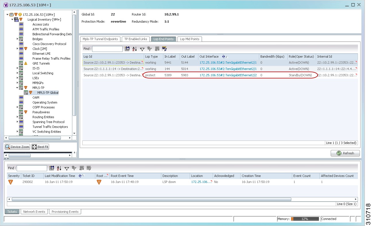
Step 4![]() Choose Logical Inventory > MPLS-TP > MPLS-TP Global > LSP End Points.
Choose Logical Inventory > MPLS-TP > MPLS-TP Global > LSP End Points.
Step 5![]() The LSP End Points tab contains the following information related to LSP redundancy service (see Figure 17-11):
The LSP End Points tab contains the following information related to LSP redundancy service (see Figure 17-11):
Figure 17-11 LSP End Points Tab in Logical Inventory
Applying an MPLS-TP Tunnel Overlay
You can select and display an overlay of a specific MPLS-TP tunnel on top of the devices displayed in a map view. The overlay is a snapshot of the network that visualizes the flows between the sites and tunnel peers. When an MPLS-TP tunnel is selected in the map, the following elements are highlighted in the map:
All elements and links that are not part of the MPLS-TP tunnel are dimmed.
To apply an MPLS-TP tunnel overlay:
Step 1![]() In the Vision client, display the network map on which you want to apply an overlay.
In the Vision client, display the network map on which you want to apply an overlay.
Step 2![]() From the main toolbar, click Choose Overlay Type and choose MPLS-TP tunnel.
From the main toolbar, click Choose Overlay Type and choose MPLS-TP tunnel.
The Select MPLS-TP tunnel Overlay dialog box is displayed.
Step 3![]() Do one of the following:
Do one of the following:
The search condition is “contains.” Search strings are case-insensitive. For example, if you choose the Name category and enter “net,” the Vision client displays VPNs “net” and “NET” in the names whether net appears at the beginning, middle, or at the end of the name: for example, Ethernet.
Step 4![]() Select the MPLS-TP tunnel overlay you want to apply to the map.
Select the MPLS-TP tunnel overlay you want to apply to the map.
The elements and links used by the selected MPLS-TP tunnel are highlighted in the network map, and the MPLS-TP tunnel name is displayed in the window title bar as shown in Figure 17-12.
Figure 17-12 MPLS-TP Tunnel Overlay
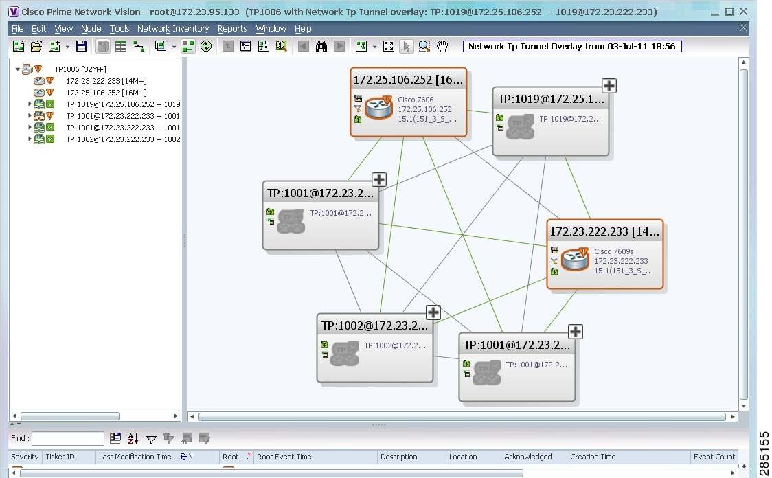
Note![]() An overlay is a snapshot taken at a specific point in time and does not reflect changes that occur in the service. As a result, the information in an overlay can become stale. To update the overlay, click Refresh Overlay in the main toolbar.
An overlay is a snapshot taken at a specific point in time and does not reflect changes that occur in the service. As a result, the information in an overlay can become stale. To update the overlay, click Refresh Overlay in the main toolbar.
Viewing VPNs
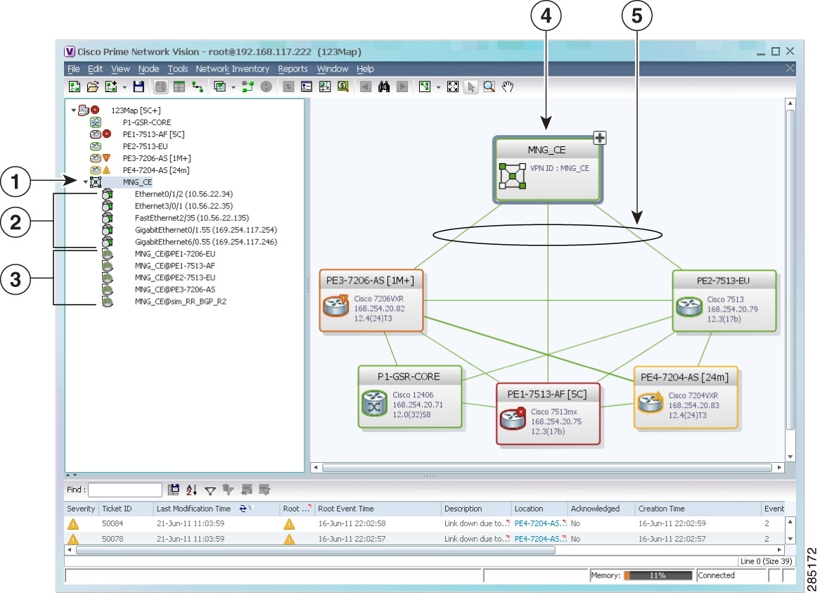
Figure 17-13 shows a VPN displayed in the Vision client map view. In this example, the VPN is selected in the navigation pane, so the VPN details, such as virtual routers and IP interfaces, are not shown in the map view.
Figure 17-13 VPN in Vision Map
|
|
|
||
|
|
|
||
|
|
|||
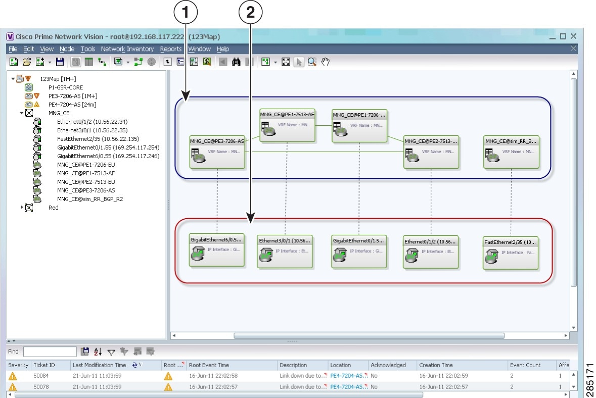
Figure 17-14 shows a VPN with details, including virtual routers and sites, in the Vision client map view.
Figure 17-14 VPN in Vision Map with VRFs and Sites
|
|
|
|
|
The the Vision client navigation pane displays the VPN business elements in a tree-and-branch representation. Each business element is represented by an icon in a color that reflects the highest alarm severity. The icon might also have a management state badge or alarm. For more information about icon severity colors and badges, see Interpreting the Badges and Colors of an NE.
Table 17-6 shows the VPN icons in the Vision client map view.
The highest level of the navigation pane displays the root or map name. The branches display the VPN and aggregated business elements as well as their names. The Layer 3 VPN sub-branch displays the virtual routers and sites contained in the VPN along with the names of the business elements. In addition, CE devices can be displayed in the Layer 2 and Layer 3 VPN sub-branches. If you select an aggregated business element in the navigation pane, the map view displays the business elements contained within the aggregated business element.
|
|
|
|---|---|

|
|

|
|

|
|

|
The the Vision client map view displays the VPN business elements and aggregated business elements loaded in the map view, along with the names of the business elements. In addition, the map view displays the VPN topology (between the virtual routers in the VPNs) and the topology and associations between other business elements. After you select the root in the navigation pane, the map view displays all the VPNs.
The Vision client presents tickets related to the map in the ticket area, which allows you to view and manage the VPN tickets.
Viewing Additional VPN Properties
The Vision client allows you to select any element in the navigation pane or map view and view additional underlying properties. To view additional properties for an object, either double-click it or right-click it and choose Properties. Table 17-7 shows the additional properties available for VPN entities.
Managing VPNs
The following topics describe:
Creating a VPN
You can change business configurations by manually creating VPNs. The VPNs that are manually created do not contain virtual routers and sites.
Step 1![]() In the Vision client navigation pane, select the map root.
In the Vision client navigation pane, select the map root.
Step 2![]() From the File menu, choose Add to Map > VPN > New.
From the File menu, choose Add to Map > VPN > New.
Step 3![]() In the Create VPN dialog box, enter the following:
In the Create VPN dialog box, enter the following:
Note![]() VPN business element names are case sensitive.
VPN business element names are case sensitive.
Note![]() If a path is not specified to an icon, the default VPN icon is used (for more information about icons, see Table 17-6).
If a path is not specified to an icon, the default VPN icon is used (for more information about icons, see Table 17-6).
The new VPN is added to the VPN list in the Add VPN dialog box.
For more information about loading the newly created VPN in the service view map, see Adding a VPN to a Map.
Adding a VPN to a Map
You can add a VPN to a map view if the VPN was previously created by a user or discovered by Prime Network and are not currently displayed in the map.
Note![]() Adding a VPN affects other users if they are working with the same map.
Adding a VPN affects other users if they are working with the same map.
To add an existing VPN to a map:
Step 1![]() In the Vision client, display the map to which you want to add the VPN.
In the Vision client, display the map to which you want to add the VPN.
Step 2![]() Do either of the following:
Do either of the following:
The Add VPN dialog box is displayed.
Step 3![]() Do either of the following:
Do either of the following:
The search condition is “contains.” Search strings are case-insensitive. For example, if you choose the Name category and enter “net,” the Vision client displays VPNs “net” and “NET” in the names whether net appears at the beginning, middle, or at the end of the name.
Step 4![]() Select the VPN that you want to add to the map.
Select the VPN that you want to add to the map.

Tip Press Shift or Ctrl to choose multiple adjoining or nonadjoining VPNs.
The VPN is displayed in the navigation pane and the selected map or subnetwork in the Vision client window content pane. In addition, any tickets are displayed in the ticket area.
When a VPN service is added to a map, then a new link is available between the ethernet flow point that represents the pseudowire headend port and the site in the VPN to which it is connected.
If your network has a L3VPN connected to a pseudowire via a PWHe, then EVC will also include the L3VPN in the EVC that contains the pseudowire.
Removing a VPN from a Map
You can remove one or more VPNs from the current active map. This change does not affect other maps. Removing a VPN from a map does not remove it from the Prime Network database. The VPN will appear in the Add VPN dialog box, so you can add it back to the map at any time.
When removing VPNs from maps, keep the following in mind:
- Removing a VPN affects other users if they are working with the same map view.
- This option does not change the business configuration or database.
- You cannot remove virtual routers or sites from the map without removing the VPN.
To remove a VPN, in the Vision client pane or map view, right-click the VPN and choose Remove from Map.
The VPN is removed from the map view along with all VPN elements, such as connected CE devices. Remote VPNs (extranets) are not removed.
Note![]() If the routing information changes after an overlay is applied, the changes do not appear in the current overlay. Click Refresh Overlay to update the routing information.
If the routing information changes after an overlay is applied, the changes do not appear in the current overlay. Click Refresh Overlay to update the routing information.
Moving a Virtual Router Between VPNs
You can move a virtual router (including its sites) from one VPN to another after you create a VPN and add it to the service view map.
Note![]() Moving a virtual router moves all of its sites as well.
Moving a virtual router moves all of its sites as well.
Step 1![]() In the Vision client navigation pane or map, right-click the virtual router and choose Edit > Move selected.
In the Vision client navigation pane or map, right-click the virtual router and choose Edit > Move selected.
Step 2![]() Right-click the required VPN in the navigation pane or map to where you want to move the virtual router and choose Edit > Move here.
Right-click the required VPN in the navigation pane or map to where you want to move the virtual router and choose Edit > Move here.

The virtual router and its sites are displayed under the selected VPN in the navigation pane and in the map.
Working with VPN Overlays
The following topics describe:
- Applying VPN Overlays
- Managing a VPN Overlay Display in the Map View
- Displaying VPN Callouts in a VPN Overlay
Applying VPN Overlays
You can select and display an overlay of a specific VPN on top of the devices displayed in a map view. The overlay is a snapshot of the network that visualizes the flows between the sites and tunnel peers. When one network VPN is selected in the network map, the PE routers, MPLS routers, and physical links that carry the LSP used by the VPN are highlighted in the network map. All the devices and links that are not part of the VPN are dimmed.
The VPN service overlay allows you to isolate the parts of a network that are being used by a particular service. This information can then be used for troubleshooting. For example, the overlay can highlight configuration or design problems when bottlenecks occur and all the site interlinks use the same link.
Step 1![]() In the Vision client, display the network map on which you want to apply an overlay.
In the Vision client, display the network map on which you want to apply an overlay.
Step 2![]() From the main toolbar, click Choose Overlay Type and choose VPN.
From the main toolbar, click Choose Overlay Type and choose VPN.
The Select VPN Overlay dialog box is displayed.
Step 3![]() Do one of the following:
Do one of the following:
The search condition is “contains.” Search strings are case-insensitive. For example, if you choose the Name category and enter “net,” the Vision client displays VPNs “net” and “NET” in the names whether net appears at the beginning, middle, or at the end of the name: for example, Ethernet.
Step 4![]() Select the VPN overlay that you want to apply to the map.
Select the VPN overlay that you want to apply to the map.
The PE routers, MPLS routers, and physical links used by the selected VPN are highlighted in the network map. The VPN name is displayed in the title of the window.
Note![]() An overlay is a snapshot taken at a specific point in time and does not reflect changes that occur in the service. As a result, the information in an overlay can become stale. To update the overlay, click Refresh Overlay in the main toolbar.
An overlay is a snapshot taken at a specific point in time and does not reflect changes that occur in the service. As a result, the information in an overlay can become stale. To update the overlay, click Refresh Overlay in the main toolbar.
Managing a VPN Overlay Display in the Map View
After a VPN overlay is applied to a map, you can manage its display by using the overlay tools in the main toolbar:
- To display the overlay, click Show Overlay on the main toolbar.
- To hide an active overlay, click Hide Overlay on the main toolbar.
Note![]() The Show Overlay button is a toggle. When clicked, the overlay is displayed. When clicked again, the overlay is hidden.
The Show Overlay button is a toggle. When clicked, the overlay is displayed. When clicked again, the overlay is hidden.
Displaying VPN Callouts in a VPN Overlay
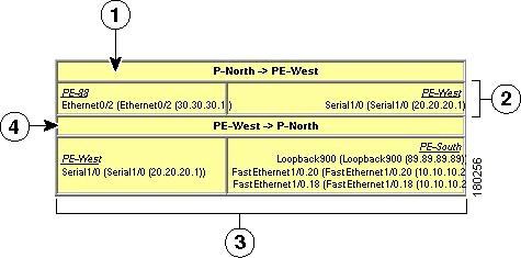
You can display or hide the callouts for VPN links displayed in a VPN overlay to show the details of the sites that are interlinked through the selected links. The callouts (see Figure 17-15) enable you to view the VPN traffic links for a specific link (either bidirectional or unidirectional).
Note![]() The link must be displayed in the VPN overlay and not dimmed for you to display the link callouts.
The link must be displayed in the VPN overlay and not dimmed for you to display the link callouts.
To display or hide the callouts:
Step 1![]() In the Vision client window, display the map view with the VPN overlay.
In the Vision client window, display the map view with the VPN overlay.
Step 2![]() Right-click the required link in the map view and choose Show Callouts.
Right-click the required link in the map view and choose Show Callouts.
Step 3![]() To hide the callouts, right-click the link in the map view that is displaying the callouts and choose Hide Callouts.
To hide the callouts, right-click the link in the map view that is displaying the callouts and choose Hide Callouts.
Monitoring MPLS Services
The following topics provide details for viewing MPLS services and technologies:
- Viewing VPN Properties
- Viewing Site Properties
- Viewing VRF Properties
- Viewing VRF Egress and Ingress Adjacents
- Viewing Routing Entities
- Viewing Label Switched Entity Properties
- Viewing MP-BGP Information
- Viewing BFD Session Properties
- Viewing Cross-VRF Routing Entries
- Viewing Pseudowire End-to-End Emulation Tunnels
- Viewing MPLS TE Tunnel Information
Viewing VPN Properties
To view the properties of a VPN:
Step 1![]() In the Vision client navigation pane or map view, do either of the following:
In the Vision client navigation pane or map view, do either of the following:
The VPN Properties window displays the following information:
Step 2![]() Click Close to close the VPN Properties dialog box.
Click Close to close the VPN Properties dialog box.
Viewing Site Properties
The Vision client enables you to view site properties, including the interfaces that are configured on the PE device. The displayed properties reflect the configuration that Prime Network automatically discovered for the device.
To view site properties, in the Vision client navigation pane or map view, right-click the required site and choose Properties.
Table 17-8 describes the information that is displayed in the Router IP Interface Properties window:
|
|
|
|---|---|
Element and interface associated with the site, hyperlinked to its entry in physical inventory. |
|
|
|
|
| Note If the site is an IPv6 VPN over MPLS with IPv6 addresses provisioned, the IPv6 addresses are displayed. For more information, see Viewing IPv6 Information (6VPE). |
|
Viewing VRF Properties
The Vision client enables you to view VRF properties, including the VRF route distinguisher, import and export route targets, and any provisioned sites and VRF routes.
To view VRF properties, do either of the following in map view:
- Double-click the element configured for VRFs.
- Expand the required VPN and double-click the virtual router.
The VRF properties window is displayed as shown in Figure 17-16.
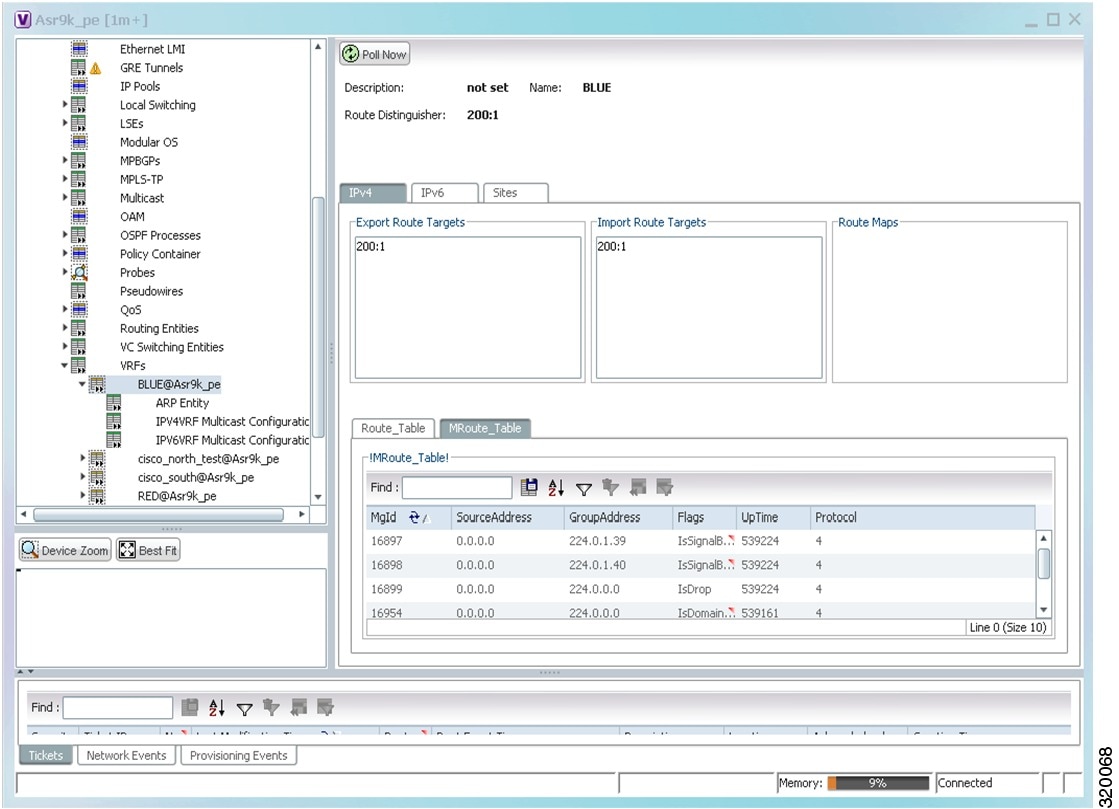
The VRF Properties window contains the VRF routing table for the device. The table is a collection of routes that are available or reachable to all the destinations or networks in the VRF. The forwarding table also contains MPLS encapsulation information.
Table 17-9 describes the information displayed in the VRF Properties window.
Note![]() The VRF Properties window only displays properties and attributes that are provisioned in the VRF. You might not see all the fields and tabs described in Table 17-9.
The VRF Properties window only displays properties and attributes that are provisioned in the VRF. You might not see all the fields and tabs described in Table 17-9.
|
|
|
|---|---|
|
|
|
The Associated VNI field in the content pane displays the VXLAN ID associated with the VRF. You can click the link to go to the corresponding VNI row in the VNI Details pane. |
|
|
|
|
|
|
|
|
|
|
Name of the outgoing interface; displayed if the Routing Protocol type is local. |
|
Routing protocol used to communicate with the other sites and VRFs: BGP or local. |
|
Border Gateway Protocol (BGP) next hop. This is the PE address from which to continue to get to a specific address. This field is empty when the routing entry goes to the CE. |
|
Innermost label that is expected when MPLS traffic is received. |
|
|
|
|
The source IP address from where the multicast information is sent. |
|
|
|
|
Element and interface associated with the site, hyperlinked to its entry in physical inventory. |
|
If a rate limit is configured on an IP interface, the limit is shown as an IP interface property. This option is checked when a rate limit is defined on the IP interface, meaning the access list is a rate limit access list. IP interface traffic is measured and includes the average rate, normal burst size, excess burst size, conform action, and exceed action. Note Double-clicking a row displays the properties of the IP interface. When a rate limit is configured on the IP interface, the Rate Limits tab is displayed. For more information about rate limits, see Viewing Rate Limit Information. Note The Input Access, Output Access, and Rate Limits parameters apply only to certain operating systems, such as Cisco IOS. |
|
Name of the business element to which the interface is attached. |
|
Viewing VRF Multicast Configuration details
To view global multicast configuration details for a VRF:
Step 1![]() Right-click on the required device and select Inventory.
Right-click on the required device and select Inventory.
Step 2![]() In the Inventory window, choose Logical Inventory > VRFs > vrf (where vrf is the required VRF) > IPV4VRF Multicast Configuration or IPV6VRF Multicast Configuration. The route policies configured on the device are displayed in the content pane.
In the Inventory window, choose Logical Inventory > VRFs > vrf (where vrf is the required VRF) > IPV4VRF Multicast Configuration or IPV6VRF Multicast Configuration. The route policies configured on the device are displayed in the content pane.
Table 17-10 describes the information that is displayed in the Router IP Interface Properties window:
|
|
|
|---|---|
The non-stop forwarding (NSF) information configured for the VRF. |
|
Viewing VRF Egress and Ingress Adjacents
The Vision client enables you to view the exporting and importing Neighbours by displaying the VRF egress and ingress adjacents. In addition, you can view the connectivity between the VRFs for the route targets and view their properties. For example, if VRF A retrieved route target import X, you can view all VRFs that export X as a route target whether it is in the same or another VPN.
To display the VRF egress and ingress adjacents, you can use either an element configured for VRFs or a virtual router:
a.![]() Double-click the element configured for VRFs.
Double-click the element configured for VRFs.
b.![]() In the Inventory window, choose Logical Inventory > VRFs > vrf where vrf is the required VRF.
In the Inventory window, choose Logical Inventory > VRFs > vrf where vrf is the required VRF.
c.![]() Right-click the required VRF and choose Show VRF Egress Adjacents or Show VRF Ingress Adjacents.
Right-click the required VRF and choose Show VRF Egress Adjacents or Show VRF Ingress Adjacents.
- To use a virtual router, right-click the required VRF in the navigation pane, and choose Show VRF Egress Adjacents or Show VRF Ingress Adjacents.
Table 17-11 describes the information displayed in the Adjacents window.
|
|
|
|---|---|
Viewing Routing Entities
Step 1![]() Right-click the required device in the Vision client and choose Inventory.
Right-click the required device in the Vision client and choose Inventory.
Step 2![]() In the logical inventory window, choose Logical Inventory > Routing Entities > Routing Entity.
In the logical inventory window, choose Logical Inventory > Routing Entities > Routing Entity.
The routing information is displayed as shown in Figure 17-17.
Figure 17-17 Routing Entity Table
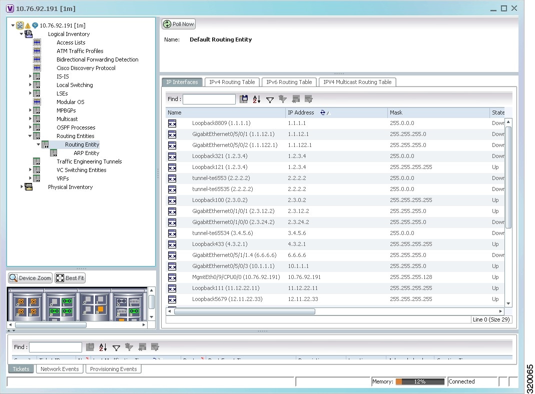
Table 17-12 describes the information that is displayed in the Routing Entity table.
|
|
|
|---|---|
|
|
|
Interface associated with the routing entity, hyperlinked to its location in physical inventory. |
|
If an input access list is assigned to an IP interface, the list is shown as an IP interface property, and a hyperlink highlights the related access list in the Access List table. When an access list is assigned to the inbound traffic on an IP interface, the actions assigned to the packet are performed. |
|
If a VRRP group is configured on an IP interface, the information is shown as an IP interface property. This option is checked when a rate limit is defined on the IP interface. Note Double-clicking a row displays the properties of the IP interface. When a VRRP group is configured on an IP interface, the VRRP Groups tab is displayed in the IP Interface Properties window. For more information, see Viewing VRRP Information. |
|
If an output access list is assigned to an IP interface, the list is shown as an IP interface property, and a hyperlink highlights the related access list in the Access List table. When an access list is assigned to the outbound traffic on an IP interface, the actions assigned to the packet are performed. |
|
If a rate limit is configured on an IP interface, the limit is shown as an IP interface property. This option is checked when a rate limit is defined on the IP interface, meaning the access list is a rate limit access list. IP interface traffic is measured and includes the average rate, normal burst size, excess burst size, conform action, and exceed action. Note Double-clicking a row displays the properties of the IP interface. When a rate limit is configured on the IP interface, the Rate Limits tab is displayed. For more information, see Viewing Rate Limit Information. Note The Input Access, Output Access, and Rate Limits parameters apply only to certain operating systems, such as Cisco IOS. |
|
Name of the business element to which the interface is attached. |
|
|
|
|
Routing type: Direct, Indirect, Static, Other, Invalid, or Unknown. |
|
IP address from which to continue to get to a specific address. This field is empty when the routing entry goes to a PE router. |
|
The source IP address from where the multicast information is sent. |
|
Routing protocol used to communicate with the other sites: BGP |
|
Viewing IPv4 Label in BGP Routes
The labeled BGP IPv4 (RFC 3107) enables BGP to distribute MPLS label along the routes it advertises. The label mapping information for a particular route is added in the same BGP update message that is used to distribute the route itself. The label mapping information is carried as a part of the Network Layer Reachability Information (NLRI) in the multiprotocol extension attributes. Hence, the use of any other label distribution protocol is eliminated.
The outer label again identifies the LSP and the inner label identifies the MPLS service. In this case, the RFC 3107 edge device replaces the outer label with two labels, generating a three-label stack.
In Prime Network, the IPv4 BGP Label Routing table displays incoming and outgoing labels. Path tracer follows a service that relies on RFC 3107 and it reflects the BGP label in the MPLS label stack.
RFC3107 is supported on the following device types: ASR9K, ASR901, ASR903, and ME3600/3800X.
To view the BGP label information:
Step 1![]() Double-click the required element in the Vision client.
Double-click the required element in the Vision client.
Step 2![]() Choose Logical Inventory > Routing Entities > Routing Entity.
Choose Logical Inventory > Routing Entities > Routing Entity.
Step 3![]() In the IPv4 BGP Label Routing table, view the details of incoming and outgoing labels.
In the IPv4 BGP Label Routing table, view the details of incoming and outgoing labels.
Table 17-13 describes the information in the IPv4 BGP Label Routing Table tab.
Table 17-13 IPv4 BGP Label Routing Table Properties
|
|
|
|---|---|
Routing protocol used to communicate with the other sites: BGP |
Viewing the ARP Table
Step 1![]() Right-click the required device in the Vision client and choose Inventory.
Right-click the required device in the Vision client and choose Inventory.
Step 2![]() In the logical inventory window, choose Logical Inventory > Routing Entities > Routing Entity > ARP.
In the logical inventory window, choose Logical Inventory > Routing Entities > Routing Entity > ARP.
Table 17-14 describes the information that is displayed in the ARP table.
Viewing the NDP Table
Neighbor Discovery Protocol (NDP) is used with IPv6 to discover other nodes, determine the link layer addresses of other nodes, find available routers, and maintain reachability information about the paths to other active Neighbour nodes.
- Router discovery
- Autoconfiguration of addresses (stateless address autoconfiguration [SLAAC])
- IPv6 address resolution (replaces Address Resolution Protocol [ARP])
- Neighbour reachability (neighbour unreachability detection [NUD])
- Duplicate address detection (DAD)
- Redirection
Step 1![]() Right-click the required device in the Vision client and choose Inventory.
Right-click the required device in the Vision client and choose Inventory.
Step 2![]() In the logical inventory window, choose Logical Inventory > Routing Entities > Routing Entity > ARP Entity.
In the logical inventory window, choose Logical Inventory > Routing Entities > Routing Entity > ARP Entity.
Step 3![]() Click the NDP Table tab.
Click the NDP Table tab.
Figure 17-18 shows an example of the NDP Table tab.
Figure 17-18 NDP Table in Logical Inventory
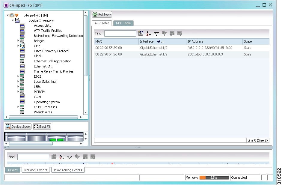
Table 17-15 describes the information displayed for NDP.
Viewing Rate Limit Information
To view rate limit information:
Step 1![]() Right-click the required element in the Vision client and choose Inventory.
Right-click the required element in the Vision client and choose Inventory.
Step 2![]() In the logical inventory window, choose Logical Inventory > Routing Entities > Routing Entity.
In the logical inventory window, choose Logical Inventory > Routing Entities > Routing Entity.
Step 3![]() In the IP Interfaces tab, double-click the required interface to view the IP interface properties. If a rate limit is configured on the IP interface, the Rate Limits tab is displayed.
In the IP Interfaces tab, double-click the required interface to view the IP interface properties. If a rate limit is configured on the IP interface, the Rate Limits tab is displayed.
Note![]() Rate Limit information applies only to certain operating systems, such as Cisco IOS.
Rate Limit information applies only to certain operating systems, such as Cisco IOS.
Table 17-16 describes the information that is displayed in the Rate Limits tab of the IP Interface Properties dialog box.
Viewing VRRP Information
Virtual Router Redundancy Protocol (VRRP) is a non-proprietary redundancy protocol that is designed to increase the availability of the static default gateway servicing hosts on the same subnet. This increased reliability is achieved by advertising a virtual router (a representation of master and backup routers acting as a group) as a default gateway to the hosts instead of one physical router. Two or more physical routers are then configured to stand for the virtual router, with only one doing the actual routing at any given time. If the current physical router that is routing the data on behalf of the virtual router fails, another physical router automatically replaces it. The physical router that forwards data on behalf of the virtual router is called the master router; physical routers standing by to take over for the master router if needed are called backup routers.
Step 1![]() Double-click the required element in the Vision client.
Double-click the required element in the Vision client.
Step 2![]() In logical inventory, choose Logical Inventory > Routing Entities > Routing Entity.
In logical inventory, choose Logical Inventory > Routing Entities > Routing Entity.
Step 3![]() In the IP Interfaces tab, double-click the required interface to view the IP interface properties. If VRRP is configured on the IP interface, the VRRP Groups tab is displayed.
In the IP Interfaces tab, double-click the required interface to view the IP interface properties. If VRRP is configured on the IP interface, the VRRP Groups tab is displayed.
Figure 17-19 VRRP Properties in IP Interface Properties Window
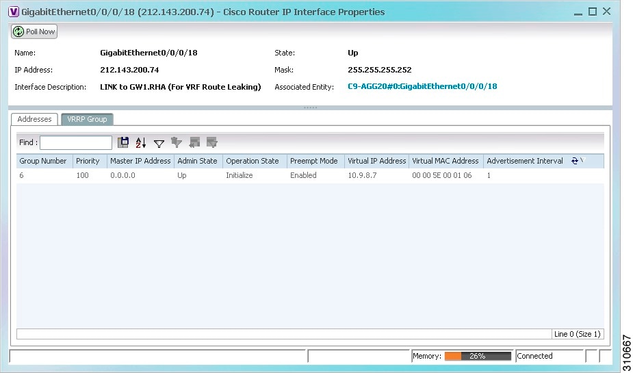
Table 17-17 describes the information in the VRRP Groups tab.
Viewing Label Switched Entity Properties
Logical inventory can display any or all of the following tabs for label switched entities, depending on the configuration:
- Label Switching Table—Describes the MPLS label switching entries used for traversing MPLS core networks.
- LDP Neighbours—Details all MPLS interface peers that use the Label Distribution Protocol (LDP). LDP enables Neighbouring provider (P) or PE routers acting as label switch routers (LSRs) in an MPLS-aware network to exchange label prefix binding information, which is required to forwarding traffic. The LSRs discover potential peers in the network with which they can establish LDP sessions in order to negotiate and exchange the labels (addresses) to be used for forwarding packets.
Two LDP peer discovery types are supported:
–![]() Basic discovery—Used to discover directly connected LDP LSRs. An LSR sends hello messages to the all-routers-on-this-subnet multicast address, on interfaces for which LDP has been configured.
Basic discovery—Used to discover directly connected LDP LSRs. An LSR sends hello messages to the all-routers-on-this-subnet multicast address, on interfaces for which LDP has been configured.
–![]() Extended discovery—Used between indirectly connected LDP LSRs. An LSR sends targeted hello messages to specific IP addresses. Targeted sessions are configured because the routers are not physically connected, and broadcasting would not reach the peers. The IP addresses of both peers are required for extended discovery.
Extended discovery—Used between indirectly connected LDP LSRs. An LSR sends targeted hello messages to specific IP addresses. Targeted sessions are configured because the routers are not physically connected, and broadcasting would not reach the peers. The IP addresses of both peers are required for extended discovery.
If two LSRs are connected with two separate interfaces, two LDP discoveries are performed.
- MPLS Interfaces—Contains information on MPLS interfaces and whether traffic engineering tunnels are configured on an interface.
- MPLS Label Range—Identifies whether MPLS uses static or dynamic routing, and the label range.
- Traffic Engineering LSPs—Describes the MPLS traffic engineering Label Switched Paths (LSPs) provisioned on the switch entity. MPLS traffic engineering LSP, an extension to MPLS TE, provides flexibility when configuring LSP attributes for MPLS TE tunnels.
- VRF Table—Describes MPLS paths that terminate locally at a VRF.
To view information for label switched entities:
Step 1![]() Double-click the required device in the Vision client.
Double-click the required device in the Vision client.
Step 2![]() In the logical inventory window, choose Logical Inventory > LSEs > Label Switching.
In the logical inventory window, choose Logical Inventory > LSEs > Label Switching.
Table 17-18 describes the information that is displayed for label switched entities.
Step 3![]() Double-click an entry in any of the tables to view additional properties for that entry.
Double-click an entry in any of the tables to view additional properties for that entry.
|
|
|
|---|---|
Multicast Label Switching (mLADP)
Multicast Label Distribution protocol (mLDP) provides extensions to the Label Distribution Protocol (LDP) for the setup of point-to-multipoint (P2MP) and multipoint-to-multipoint (MP2MP) Label Switched Paths (LSPs) in MPLS networks. A P2MP LSP allows traffic from a single root (or ingress) node to be delivered to a number of leaf (or egress) nodes.
A MP2MP LSP allows traffic from multiple ingress nodes to be delivered to multiple egress nodes. Only a single copy of the packet will be sent on any link traversed by a multipoint LSP. Container is the holder of MPLS MLDP databases and neighbors instances for Multicast.
Viewing MLDP Database Information
To view the MLDP database information:
Step 1![]() Double-click the required device in the Vision client.
Double-click the required device in the Vision client.
Step 2![]() In the logical inventory window, choose Logical Inventory > LSEs > Label Switching > Multicast Label Switching > Databases. The database information is displayed in the MLDP Databases content pane.
In the logical inventory window, choose Logical Inventory > LSEs > Label Switching > Multicast Label Switching > Databases. The database information is displayed in the MLDP Databases content pane.
Step 3![]() Select a database from the content pane, right-click and choose the Properties option. The MLDP Database Properties dialog box is displayed. You can click on the tabs to view more details.
Select a database from the content pane, right-click and choose the Properties option. The MLDP Database Properties dialog box is displayed. You can click on the tabs to view more details.
Table 17-20 describes the information that is displayed for MLDP Database Properties dialog box.
Viewing the MLDP Neighbors Information
To view information of MLDP neighbors:
Step 1![]() Double-click the required device in the Vision client.
Double-click the required device in the Vision client.
Step 2![]() In the logical inventory window, choose Logical Inventory > LSEs > Label Switching > Multicast Label Switching > MLDP Neighbors. The MLDP peer information is displayed in the MLDP Peers content pane.
In the logical inventory window, choose Logical Inventory > LSEs > Label Switching > Multicast Label Switching > MLDP Neighbors. The MLDP peer information is displayed in the MLDP Peers content pane.
Step 3![]() Select a peer id from the content pane, right-click and choose the Properties option. The Peer ID Properties dialog box is displayed.
Select a peer id from the content pane, right-click and choose the Properties option. The Peer ID Properties dialog box is displayed.
Table 17-21 describes the information that is displayed for Peer ID Properties dialog box.
Viewing BGP Neighbor Service Alarm with VRF Name
BGP neighbor loss VRF due to oper and BGP neighbor found service alarms are raised on the BGP links for any mis-configurations that shuts down physical interfaces or any other scenario that might break the BGP neighborship. If a BGP neighbor service alarm is configured with the VRF, the VRF name is displayed as part of the Location links for a BGP neighbor loss VRF due to oper and BGP neighbor found service alarms. For example, Figure 17-20 shows the BGP neighbor service alarms displayed with the VRF Name.
Figure 17-20 Service Alarm with VRF Name

To view the VRF details, click the links available in the Location field. For example, the following figure 17-21, shows a link properties of a BGP Service alarm with VRF Name.
Figure 17-21 Link Properties with VRF Information
Viewing MP-BGP Information
The MP-BGP branch displays information about a router’s BGP neighbors and cross-connect VRFs.
Note![]() If there are multiple MP-BGP links between two devices, the Vision client displays each link in the content pane map view.
If there are multiple MP-BGP links between two devices, the Vision client displays each link in the content pane map view.
Step 1![]() Right-click the required device in the Vision client and choose Inventory.
Right-click the required device in the Vision client and choose Inventory.
Step 2![]() In the logical inventory window, choose Logical Inventory > MPBGPs > MPBGP.
In the logical inventory window, choose Logical Inventory > MPBGPs > MPBGP.
Table 17-22 describes the information that is displayed for MP-BGP.
Viewing 6rd Tunnel Properties
IPv6 rapid deployment (6rd) is a mechanism that allows stateless tunneling of IPv6 over IPv4. For information on the devices that support 6rd, refer to Cisco Prime Network 5.1 Supported VNEs.
To view 6rd tunnel properties:
Step 1![]() In the Vision client, double-click the required device.
In the Vision client, double-click the required device.
Step 2![]() In the Inventory window, choose Logical Inventory > 6rd Tunnels.
In the Inventory window, choose Logical Inventory > 6rd Tunnels.
The 6rd tunnel properties are displayed as shown in Figure 17-22.
Figure 17-22 6rd Tunnel Properties in Logical Inventory
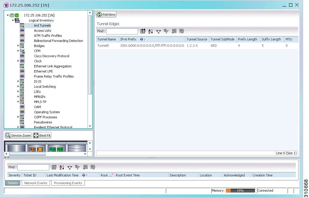
Table 17-23 describes the information displayed for 6rd tunnels.
Viewing BFD Session Properties
Bidirectional Forwarding Detection (BFD) is used to detect communication failures between two elements, or endpoints, that are connected by a link, such as a virtual circuit, tunnel, or LSP. BFD establishes sessions between the two endpoints over the link. If more than one link exists, BFD establishes a session for each link.
Prime Network supports BFD with the following protocols: BGP, IPv4 (static), IPv6 (static), IS-IS, LAG (Ether channel), MPLS TE, MPLS-TP, and OSPF.
To view BFD session properties that are configured on an element:
Step 1![]() In the Vision client, double-click the required device.
In the Vision client, double-click the required device.
Step 2![]() In the Inventory window, choose Logical Inventory > Bidirectional Forwarding Detection.
In the Inventory window, choose Logical Inventory > Bidirectional Forwarding Detection.
The properties for BFD sessions are displayed as shown in Figure 17-23.
Figure 17-23 BFD Session Properties
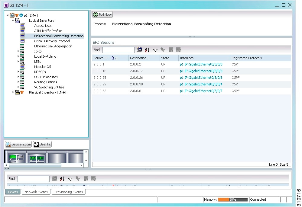
Table 17-24 describes the information displayed for BFD sessions.
For MPLS-TP BFD sessions, the information in Table 17-25 is displayed.
Step 3![]() To view additional properties, double-click the required entry in the Sessions table.
To view additional properties, double-click the required entry in the Sessions table.
Table 17-26 describes the information that is displayed in the Session Properties window.
BFD Single-Hop Authentication
The BFD Single-Hop Authentication feature enables authentication for single-hop Bidirectional Forwarding Detection (BFD) sessions between two directly connected devices. This feature supports Message Digest 5 (MD5) and Secure Hash Algorithm 1 (SHA-1) authentication types. The BFD templates can be configured only if the BFD sessions are enabled.
BFD Templates Support
BFD (Bidirectional Forwarding Detection Templates) are the new features added in CPT devices. Prime Network uses the below Telnet or CLI Command to get the BFD templates in existing CPT devices.
Cerent Trap Support
Cerent traps are alarms supported for CPT devices. There are 170 traps supported.There are various kinds of traps supported which are listed below:
The alarms can be categorized by their severity such as Critical, Major, Minor, Not Reported and Not Alarmed. Examples of each severity categories are as follows:
- Critical- Equipment failure
- Major- High Voltage, Battery Failure
- Minor- Loss of frame, Loss of signal
- Not Reported- Unqualified PPM Inserted
- Not Alarmed- Transit Node Clock Traceable
Change Settings in Cisco Transport Controller (CTC)
Any configurations settings made in CPT should be done through CTC. To receive traps in a particular server, that server IP needs to be entered in the device through CTC. Most of the traps are on device dependencies.
The default trap format can be used to send the alarms through CMP tool which can be generated in Prime Network. The default trap format is given as follows:
<key name="trap"><key name=""><entry name="">sendtrap -V2 10.105.39.217 -ccellbus -r162 -o1.3.6.1.2.1.1.3.0 -mt1166470595 -o1.3.6.1.6.3.1.1.4.1.0 -md1.3.6.1.4.1.3607.6.10.30.0.1670 -o1.3.6.1.4.1.3607.6.10.100.10.20 -mo03/Nov/2001 -o1.3.6.1.4.1.3607.6.10.20.30.20.1.80.1.1670 -mi50 -o1.3.6.1.4.1.3607.6.10.20.30.20.1.20.1.1670 -mi50 -o1.3.6.1.4.1.3607.6.10.20.30.20.1.60.1.1670 -mi1 -o1.3.6.1.4.1.3607.6.10.20.30.20.1.30.1.1670 -mi0 -o1.3.6.1.4.1.3607.6.10.20.30.20.1.40.1.1670 -mi1 -o1.3.6.1.4.1.3607.6.10.20.30.20.1.50.1.1670 -mi0 -o1.3.6.1.4.1.3607.6.10.20.30.20.1.100.1.1670 -md1.3.6.1.4.1.3607.6.10.30.0.2110 -o1.3.6.1.4.1.3607.6.10.20.30.20.1.120.1.1670 -mi30 -o1.3.6.1.4.1.3607.6.10.20.30.20.1.130.1.1670 -mi10 -o1.3.6.1.4.1.3607.6.10.20.30.20.1.140.1.1670 -mi10 -o1.3.6.1.6.3.18.1.3.0 -ma10.104.120.46</entry></key></key>
Link and Port Parameters
The link and port parameters are scripts which can be navigated from Device->Port->Interface-> right click Commands->Configuration->Scripts. The link and port parameters are supported for the following auto populated UI attributes:
Viewing Configuration Scripts in Prime Network
To view the Add Loopback script:
Step 1![]() Model the device in Cisco Prime Network Administration.
Model the device in Cisco Prime Network Administration.
Step 2![]() Launch the Cisco Prime Network Vision client and choose Inventory
Launch the Cisco Prime Network Vision client and choose Inventory
Step 3![]() In the physical inventory window, choose Physical inventory >IPortConnector >Commands > Configuration >Add Loopback
In the physical inventory window, choose Physical inventory >IPortConnector >Commands > Configuration >Add Loopback
Step 4![]() Select the value Loopback from the Attribute combo box.
Select the value Loopback from the Attribute combo box.
Step 5![]() Click on Execute Now button.
Click on Execute Now button.
Step 6![]() Verify if Loopback is successfully added.
Verify if Loopback is successfully added.
To view the Remove Loopback script:
Step 1![]() Model the device in Cisco Prime Network Administration.
Model the device in Cisco Prime Network Administration.
Step 2![]() Launch the Cisco Prime Network Vision client and choose Inventory
Launch the Cisco Prime Network Vision client and choose Inventory
Step 3![]() In the physical inventory window, choose Physical inventory >IPortConnector >Commands > Configuration >Remove Loopback
In the physical inventory window, choose Physical inventory >IPortConnector >Commands > Configuration >Remove Loopback
Step 4![]() Click on Execute Now button.
Click on Execute Now button.
Step 5![]() Verify if Loopback is successfully removed.
Verify if Loopback is successfully removed.
To view the Configure CDP script:
Step 1![]() Model the device in Cisco Prime Network Administration.
Model the device in Cisco Prime Network Administration.
Step 2![]() Launch the Cisco Prime Network Vision client and choose Inventory
Launch the Cisco Prime Network Vision client and choose Inventory
Step 3![]() In the physical inventory window, choose Physical inventory >IPortConnector >Commands > Configuration >Configure CDP
In the physical inventory window, choose Physical inventory >IPortConnector >Commands > Configuration >Configure CDP
Step 4![]() Select the value CDP from the Attribute combo box.
Select the value CDP from the Attribute combo box.
Step 5![]() Click on Execute Now button.
Click on Execute Now button.
Step 6![]() Verify if CDP is successfully configured.
Verify if CDP is successfully configured.
To view the Configure Ethernet script:
Step 1![]() Model the device in Cisco Prime Network Administration.
Model the device in Cisco Prime Network Administration.
Step 2![]() Launch the Cisco Prime Network Vision client and choose Inventory
Launch the Cisco Prime Network Vision client and choose Inventory
Step 3![]() In the physical inventory window, choose Physical inventory >IPortConnector >Commands > Configuration >Configure Ethernet
In the physical inventory window, choose Physical inventory >IPortConnector >Commands > Configuration >Configure Ethernet
Step 4![]() Select the value Admin Status from the Attribute combo box.
Select the value Admin Status from the Attribute combo box.
Step 5![]() Click on Execute Now button.
Click on Execute Now button.
Step 6![]() Verify if Ethernet is successfully configured.
Verify if Ethernet is successfully configured.
To view the Configure L2 Control Protocol script:
Step 1![]() Model the device in Cisco Prime Network Administration.
Model the device in Cisco Prime Network Administration.
Step 2![]() Launch the Cisco Prime Network Vision client and choose Inventory
Launch the Cisco Prime Network Vision client and choose Inventory
Step 3![]() In the physical inventory window, choose Physical inventory >IPortConnector >Commands > Configuration >Configure L2 Control Protocol
In the physical inventory window, choose Physical inventory >IPortConnector >Commands > Configuration >Configure L2 Control Protocol
Step 4![]() Select the value STP from the Attribute combo box.
Select the value STP from the Attribute combo box.
Step 5![]() Click on Execute Now button.
Click on Execute Now button.
Step 6![]() Verify if L2 Control Protocol is successfully configured.
Verify if L2 Control Protocol is successfully configured.
To view the Configure Port Parameters script:
Step 1![]() Model the device in Cisco Prime Network Administration.
Model the device in Cisco Prime Network Administration.
Step 2![]() Launch the Cisco Prime Network Vision client and choose Inventory
Launch the Cisco Prime Network Vision client and choose Inventory
Step 3![]() In the physical inventory window, choose Physical inventory >IPortConnector >Commands > Configuration >Configure Port Parameters
In the physical inventory window, choose Physical inventory >IPortConnector >Commands > Configuration >Configure Port Parameters
Step 4![]() Select the value Reach from the Attribute combo box.
Select the value Reach from the Attribute combo box.
Step 5![]() Click on Execute Now button.
Click on Execute Now button.
Step 6![]() Verify if Port Parameters are successfully added.
Verify if Port Parameters are successfully added.
To view the Show Port Parameters script:
Step 1![]() Model the device in Cisco Prime Network Administration.
Model the device in Cisco Prime Network Administration.
Step 2![]() Launch the Cisco Prime Network Vision client and choose Inventory
Launch the Cisco Prime Network Vision client and choose Inventory
Step 3![]() In the physical inventory window, choose Physical inventory >IPortConnector >Commands > Configuration >Show Port Parameters
In the physical inventory window, choose Physical inventory >IPortConnector >Commands > Configuration >Show Port Parameters
Step 4![]() Click on Execute Now button.
Click on Execute Now button.
Step 5![]() Verify if all Port Parameters are listed.
Verify if all Port Parameters are listed.
To view the Show Ethernet Parameters script:
Step 1![]() Model the device in Cisco Prime Network Administration.
Model the device in Cisco Prime Network Administration.
Step 2![]() Launch the Cisco Prime Network Vision client and choose Inventory
Launch the Cisco Prime Network Vision client and choose Inventory
Step 3![]() In the physical inventory window, choose Physical inventory >IPortConnector >Commands > Configuration >Show Ethernet Parameters
In the physical inventory window, choose Physical inventory >IPortConnector >Commands > Configuration >Show Ethernet Parameters
Step 4![]() Click on Execute Now button.
Click on Execute Now button.
Step 5![]() Verify if Show Ethernet Parameters are listed.
Verify if Show Ethernet Parameters are listed.
To view the Show L2 Control Parameters script:
Step 1![]() Model the device in Cisco Prime Network Administration.
Model the device in Cisco Prime Network Administration.
Step 2![]() Launch the Cisco Prime Network Vision client and choose Inventory
Launch the Cisco Prime Network Vision client and choose Inventory
Step 3![]() In the physical inventory window, choose Physical inventory >IPortConnector >Commands > Configuration >Show L2 Control Parameters.
In the physical inventory window, choose Physical inventory >IPortConnector >Commands > Configuration >Show L2 Control Parameters.
Step 4![]() Click on Execute Now button.
Click on Execute Now button.
Step 5![]() Verify if all L2 Control Parameters are listed.
Verify if all L2 Control Parameters are listed.
To view the Show Configure Ethernet script:
Step 1![]() Model the device in Cisco Prime Network Administration.
Model the device in Cisco Prime Network Administration.
Step 2![]() Launch the Cisco Prime Network Vision client and choose Inventory
Launch the Cisco Prime Network Vision client and choose Inventory
Step 3![]() In the physical inventory window, choose Physical inventory >IPortConnector >Commands > Configuration >Show Configure Ethernet
In the physical inventory window, choose Physical inventory >IPortConnector >Commands > Configuration >Show Configure Ethernet
Step 4![]() Click on Execute Now button.
Click on Execute Now button.
Step 5![]() Verify if all the configured Ethernets are listed.
Verify if all the configured Ethernets are listed.
Viewing Cross-VRF Routing Entries
Cross-VRF routing entries display routing information learned from the BGP neighbors (BGP knowledge base).
To view properties for cross-VRF routing entries:
Step 1![]() Right-click the required device in the Vision client and choose Inventory.
Right-click the required device in the Vision client and choose Inventory.
Step 2![]() In the logical inventory window, choose Logical Inventory > MPBGPs > MPBGP.
In the logical inventory window, choose Logical Inventory > MPBGPs > MPBGP.
Step 3![]() Click the Cross VRFs tab.
Click the Cross VRFs tab.
Step 4![]() Double-click the required entry in the list of cross-VRFs.
Double-click the required entry in the list of cross-VRFs.
The Cross VRF Properties window is displayed, containing the information described in Table 17-27 .
|
|
|
|---|---|
|
|
|
Outgoing VRF identifier, hyperlinked to its entry in logical inventory. |
|
Viewing Pseudowire End-to-End Emulation Tunnels
The Pseudowires branch in logical inventory displays a list of the Layer 2 tunnel edge properties (per edge), including tunnel status and VC labels.
To view pseudowire properties:
Step 1![]() Right-click the required device in the Vision client and choose Inventory.
Right-click the required device in the Vision client and choose Inventory.
Step 2![]() In the logical inventory window, choose Logical Inventory > Pseudowires.
In the logical inventory window, choose Logical Inventory > Pseudowires.
The Tunnel Edges table is displayed and contains the information described in Table 17-28 .
Viewing MPLS TE Tunnel Information
Prime Network automatically discovers MPLS TE tunnels and enables you to view MPLS TE tunnel information in inventory.
To view MPLS TE tunnel information:
Step 1![]() Right-click the required device in the Vision client and choose Inventory.
Right-click the required device in the Vision client and choose Inventory.
Step 2![]() In the logical inventory window, choose Logical Inventory > Traffic Engineering Tunnels.
In the logical inventory window, choose Logical Inventory > Traffic Engineering Tunnels.
Table 17-29 describes the information that is displayed in the Tunnel Edges table.
The Traffic Engineering LSPs tab in the LSEs branch in logical inventory displays TE tunnel LSP information.
For details about the information displayed for TE tunnel LSPs, see Traffic Engineering LSPs.
Configuring VRFs
The following commands configure routes that are available or reachable to all the destinations or networks in the VRF. These commands are launched by right-clicking the VRF node and choosing Commands > Configuration. Your permissions determine whether you can run these commands (see Permissions for Managing MPLS Services). To find out if a device supports these commands, see the Cisco Prime Network 5.1 Supported Cisco VNEs.
|
|
|
|---|---|
| Configures VRF properties, including the VRF route distinguisher, import and export route targets, and any provisioned sites and VRF routes. |
|
Configuring IP Interfaces
The following IP interface commands are launched by right-clicking Routing Entities > routing entity and choosing Commands > Configuration. Your permissions determine whether you can run these commands (see Permissions for Managing IP and MPLS Multicast). To find out if a device supports these commands, see the Cisco Prime Network 5.1 Supported Cisco VNEs.
|
|
|
|---|---|
| Create Interface |
|
Auto-IP in PN
Prime network supports AUTO-IP feature in 5.1 Release. Auto-IP is an IP address configured on the interface using the Auto-IP ring command. The Auto-IP feature enables node insertion, removal and movement to any location within a ring without the need for reconfiguring the existing nodes manually. When enabled on the physical interface or the sub interface, you can discover the devices in the Auto-IP ring automatically.
Configuring Auto-IP
To configure Auto-IP, configure one of the routers in the ring as a seed router. Normally an edge router is configured as a seed router, and the Auto-IP address of the seed router is same as the IP address of the router interface in which the Auto-IP is enabled. The device, in which the Auto-IP configured with priority value 2, becomes the owner interface and assigns the IP address to the non-owner interface (Priority value for non-owner interface is 0) in the ring topology. The Link Layer Discovery Protocol (LLDP) must be enabled on the device before enabling the auto-IP functionality on a node interface.
Note![]() When you configure Auto-IP feature on the devices, by default, the priority value is 1.
When you configure Auto-IP feature on the devices, by default, the priority value is 1.
Configuring MPLS-TP
The following MPLS-TP commands are launched by right-clicking the appropriate node and choosing MPLS-TP Global > Commands > Configuration. Your permissions determine whether you can run these commands (see Permissions for Managing MPLS Services). To find out if a device supports these commands, see the Cisco Prime Network 5.1 Supported Cisco VNEs.
Note![]() To run the Global Configuration, BFD Configuration, and Link Configuration commands on the Cisco Carrier Packet Transport (CPT) System, right-click the device in the Vision client list or map view, and click Logical Inventory > CPT Context Container.
To run the Global Configuration, BFD Configuration, and Link Configuration commands on the Cisco Carrier Packet Transport (CPT) System, right-click the device in the Vision client list or map view, and click Logical Inventory > CPT Context Container.
Locking/Unlocking MPLS-TP Tunnels in Bulk
An MPLS-TP network has one or multiple LSPs running between endpoint devices. If you want to shutdown one of the interfaces in the network, the MPLS-TP packet must be diverted through an alternative LSP. This can be achieved by locking the interface. Before attempting to lock or unlock a tunnel, ensure that MPLS-TP tunnels have been configured for the link. Also, ensure that you have the appropriate rights (Configurator and above) to lock or unlock a tunnel.
The MPLS-TP bulk lockout/unlock option in Prime Network allows you to lock or unlock multiple MPLS-TP tunnels on different VNEs at the same time.
Your permissions determine whether you can run these commands (see Permissions for Managing MPLS Services). To find out if a device supports these commands, see the Cisco Prime Network 5.1 Supported Cisco VNEs.
Locking MPLS-TP Tunnels
To lock MPLS-TP tunnels in bulk:
Step 1![]() In the map view, right-click the required link and choose Properties.
In the map view, right-click the required link and choose Properties.
Step 2![]() In the link properties window, right-click on the required physical link and choose the Show MPLS-TP tunnels option. The MPLS-TP tunnels’ commands dialog box is displayed, which lists all the tunnels in the selected link.
In the link properties window, right-click on the required physical link and choose the Show MPLS-TP tunnels option. The MPLS-TP tunnels’ commands dialog box is displayed, which lists all the tunnels in the selected link.
Step 3![]() In the MPLS-TP tunnels’ commands dialog box, choose the tunnels that you want to lock and select the Lock Out option in the Commands field.
In the MPLS-TP tunnels’ commands dialog box, choose the tunnels that you want to lock and select the Lock Out option in the Commands field.
Step 4![]() Click Execute Now. You are prompted to confirm the lockout operation.
Click Execute Now. You are prompted to confirm the lockout operation.
Step 5![]() Click Yes to confirm. A message is displayed confirming that the selected tunnels have been locked. The status of the tunnel is automatically updated as Lockout(UP) after this operation.
Click Yes to confirm. A message is displayed confirming that the selected tunnels have been locked. The status of the tunnel is automatically updated as Lockout(UP) after this operation.
Unlocking MPLS-TP Tunnels
To unlock MPLS-TP tunnels in bulk:
Step 1![]() In the map view, right-click the required link and choose Properties.
In the map view, right-click the required link and choose Properties.
Step 2![]() In the link properties window, right-click on the required physical link and choose the Show MPLS-TP tunnels option. The MPLS-TP tunnels’ commands dialog box is displayed, which lists all the tunnels in the selected link.
In the link properties window, right-click on the required physical link and choose the Show MPLS-TP tunnels option. The MPLS-TP tunnels’ commands dialog box is displayed, which lists all the tunnels in the selected link.
Step 3![]() In the MPLS-TP tunnels’ commands dialog box, select the locked tunnels that you want to unlock and select the Unlock option in the Commands field.
In the MPLS-TP tunnels’ commands dialog box, select the locked tunnels that you want to unlock and select the Unlock option in the Commands field.
Step 4![]() Click Execute Now. You are prompted to confirm the unlock operation.
Click Execute Now. You are prompted to confirm the unlock operation.
Step 5![]() Click Yes to confirm. A message is displayed confirming that the selected tunnels have been unlocked. The status of the tunnels is automatically updated as Active(UP) after this operation.
Click Yes to confirm. A message is displayed confirming that the selected tunnels have been unlocked. The status of the tunnels is automatically updated as Active(UP) after this operation.
Note![]() If you attempt to unlock a tunnel that is not locked, a message is displayed indicating that there are no valid tunnels to perform the unlock operation.
If you attempt to unlock a tunnel that is not locked, a message is displayed indicating that there are no valid tunnels to perform the unlock operation.
Linear Protection for MPLS-TP
As explained earlier, MPLS-TP is the transport profile that fulfills the deployment in the network for the MPLS technology. This technology provides fast protection switching for end-to-end segments wherein the protection switching time is generally less than 50 milliseconds.
Protection switching is a mechanism wherein route and resources of a protection path are reserved for a selected working path or set of working paths.
Linear protection provides rapid and simple protection switching because it can operate between any pair of points within the network. For every working Label Switched Paths (LSP) in the network, there is a protected LSP that is not related to any other working entity. When a working LSP fails, the protected LSP is ready to take up transmission of data.
In Prime Network, the following commands are available for linear protection:
- Force Switch (Lockout)—This command is used to switch normal traffic from a working LSP to a protected LSP. This command can only be applied on a working LSP. If Force Switch is enabled, then the Working LSP becomes standby and the Protected LSP becomes active.
- Manual Switch—This command is used to switch normal traffic from a working LSP to a protected LSP. This command can be applied only on a working LSP. If Manual Switch is enabled, then the working LSP becomes standby and the protected LSP becomes active.
Note![]() The Force Switch and Manual Switch commands are both used to switch traffic from the working LSP to the protected LSP. However, if the Manual Switch command is used, and there is a failure in the protecting LSP, then the working LSP becomes active. In case of the Force Switch command, then the working LSP does not become active if there is a failure in the protecting LSP.+
The Force Switch and Manual Switch commands are both used to switch traffic from the working LSP to the protected LSP. However, if the Manual Switch command is used, and there is a failure in the protecting LSP, then the working LSP becomes active. In case of the Force Switch command, then the working LSP does not become active if there is a failure in the protecting LSP.+
- Lockout of Protecting (Lockout)—This command is used to switch traffic from the protected LSP to the working LSP. This command can be applied only on a protected LSP. If Lockout of Protecting is enabled, then the working LSP becomes active and the protected LSP becomes standby.
- Clear Force Switch (no Lockout)—This command is used to clear the force switch on a working LSP after which the working LSP becomes active and the protected LSP becomes standby.
- Clear Manual Switch—This command is used to clear the manual switch made on a working LSP, after which the working LSP becomes active and the protected LSP becomes standby.
- Clear Lockout of Protecting (no Lockout)—This command is used to clear the lockout of protecting made on a protected LSP. The working LSP becomes standby and the protected LSP becomes active after this command is executed.
Figure 17-24 depicts the MPLS-TP topology along with the working and protected LSPs:
Figure 17-24 Linear Protection for MPLS-TP
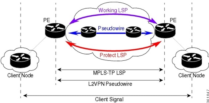
Note![]() In the above figure, you can find working and protected LSPs between two routers. In case of maintenance or network upgrade, the Force Switch and Manual Switch commands can be used to shut down the working LSP link. Similarly, the Lockout of Protecting command can be used to shut down the protected LSP link.
In the above figure, you can find working and protected LSPs between two routers. In case of maintenance or network upgrade, the Force Switch and Manual Switch commands can be used to shut down the working LSP link. Similarly, the Lockout of Protecting command can be used to shut down the protected LSP link.
To switch traffic using the Force Switch or Manual Switch command:
Step 1![]() In the map view, right-click the required link and choose Properties. A list of tunnels for the selected link is displayed.
In the map view, right-click the required link and choose Properties. A list of tunnels for the selected link is displayed.
Step 2![]() Right-click on the required physical link and choose the Manage MPLS-TP tunnels option. The MPLS-TP tunnels’ commands dialog box is displayed.
Right-click on the required physical link and choose the Manage MPLS-TP tunnels option. The MPLS-TP tunnels’ commands dialog box is displayed.
Note![]() If there are no MPLS-TP tunnels configured for the selected link, then a message indicating the absence of MPLS-TP tunnels is displayed.
If there are no MPLS-TP tunnels configured for the selected link, then a message indicating the absence of MPLS-TP tunnels is displayed.
Step 3![]() In the MPLS-TP tunnels’ commands dialog box, select the working LSP tunnel and select Force Switch (Lockout) or Manual Switch in the Commands field.
In the MPLS-TP tunnels’ commands dialog box, select the working LSP tunnel and select Force Switch (Lockout) or Manual Switch in the Commands field.
Step 4![]() Click Execute Now. You are prompted to confirm the operation.
Click Execute Now. You are prompted to confirm the operation.
Step 5![]() Click Yes to confirm. The status of the working LSP is updated as Standby and the status of the protected LSP is updated as Active after this operation.
Click Yes to confirm. The status of the working LSP is updated as Standby and the status of the protected LSP is updated as Active after this operation.
To switch traffic using the Lockout of Protecting command:
Step 1![]() In the map view, right-click the required link and choose Properties. A list of tunnels for the selected link is displayed.
In the map view, right-click the required link and choose Properties. A list of tunnels for the selected link is displayed.
Step 2![]() Right-click on the required physical link and choose the Manage MPLS-TP tunnels option. The MPLS-TP tunnels’ commands dialog box is displayed.
Right-click on the required physical link and choose the Manage MPLS-TP tunnels option. The MPLS-TP tunnels’ commands dialog box is displayed.
Step 3![]() In the MPLS-TP tunnels’ commands dialog box, select the protected LSP tunnel and select Lock of Protecting in the Commands field.
In the MPLS-TP tunnels’ commands dialog box, select the protected LSP tunnel and select Lock of Protecting in the Commands field.
Step 4![]() Click Execute Now. You are prompted to confirm the operation.
Click Execute Now. You are prompted to confirm the operation.
Step 5![]() Click Yes to confirm. The status of the working LSP is updated as Active and the status of the protected LSP is updated as Standby after this operation.
Click Yes to confirm. The status of the working LSP is updated as Active and the status of the protected LSP is updated as Standby after this operation.
To clear the Force Switch or Manual switch on a working LSP:
Step 1![]() In the map view, right-click the required link and choose Properties. A list of tunnels for the selected link is displayed.
In the map view, right-click the required link and choose Properties. A list of tunnels for the selected link is displayed.
Step 2![]() Right-click on the required physical link and choose the Manage MPLS-TP tunnels option. The MPLS-TP tunnels’ commands dialog box is displayed.
Right-click on the required physical link and choose the Manage MPLS-TP tunnels option. The MPLS-TP tunnels’ commands dialog box is displayed.
Step 3![]() In the MPLS-TP tunnels’ commands dialog box, select the working LSP tunnel that has been locked and select Clear Force Switch or Clear Manual Switch in the Commands field.
In the MPLS-TP tunnels’ commands dialog box, select the working LSP tunnel that has been locked and select Clear Force Switch or Clear Manual Switch in the Commands field.
Step 4![]() Click Execute Now. You are prompted to confirm the operation.
Click Execute Now. You are prompted to confirm the operation.
Step 5![]() Click Yes to confirm. The status of the working LSP is updated as Active and the status of the protected LSP is updated as Standby after this operation.
Click Yes to confirm. The status of the working LSP is updated as Active and the status of the protected LSP is updated as Standby after this operation.
To clear the Lockout of Protecting on a protected LSP:
Step 1![]() In the map view, right-click the required link and choose Properties. A list of tunnels for the selected link is displayed.
In the map view, right-click the required link and choose Properties. A list of tunnels for the selected link is displayed.
Step 2![]() Right-click on the required physical link and choose the Manage MPLS-TP tunnels option. The MPLS-TP tunnels’ commands dialog box is displayed.
Right-click on the required physical link and choose the Manage MPLS-TP tunnels option. The MPLS-TP tunnels’ commands dialog box is displayed.
Step 3![]() In the MPLS-TP tunnels’ commands dialog box, select the protected LSP tunnel that has been locked and select Clear Lockout of Protecting in the Commands field.
In the MPLS-TP tunnels’ commands dialog box, select the protected LSP tunnel that has been locked and select Clear Lockout of Protecting in the Commands field.
Step 4![]() Click Execute Now. You are prompted to confirm the operation.
Click Execute Now. You are prompted to confirm the operation.
Step 5![]() Click Yes to confirm. The status of the protected LSP is updated as Active and the status of the working LSP is updated as Standby after this operation.
Click Yes to confirm. The status of the protected LSP is updated as Active and the status of the working LSP is updated as Standby after this operation.
Visualization Status Enhancements- MPLS TP Tunnel
In the MPLS TP Tunnel, the following visualization status enhancements have been carried out:
Non Eligible LSPs
If the tunnel is not configured with protected LSP, i.e., the tunnel is configured with working LSP (Active-UP); the information column displays the value as Protected LSP is not configured. See Figure 17-26.This information is displayed for all non-eligible LSPs which are not eligible for bulk flow operations like FS, LOP, MS, LOCK.
Figure 17-25 Viewing the Working LSPs and Protected LSPs
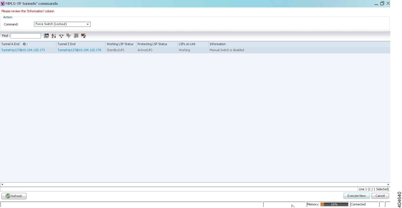
In the above Figure 17-25, both the status of Working LSP and the Protected LSP are in up state. So, the Information field is blank.
Lockout State
In the Lockout State, information value has been changed. If the Working LSP is down, it displays Working LSP is Locked Out. If the Protected LSP is down, it displays that the Protected LSP is Locked Out
Figure 17-26 Viewing the Lockout States of LSP
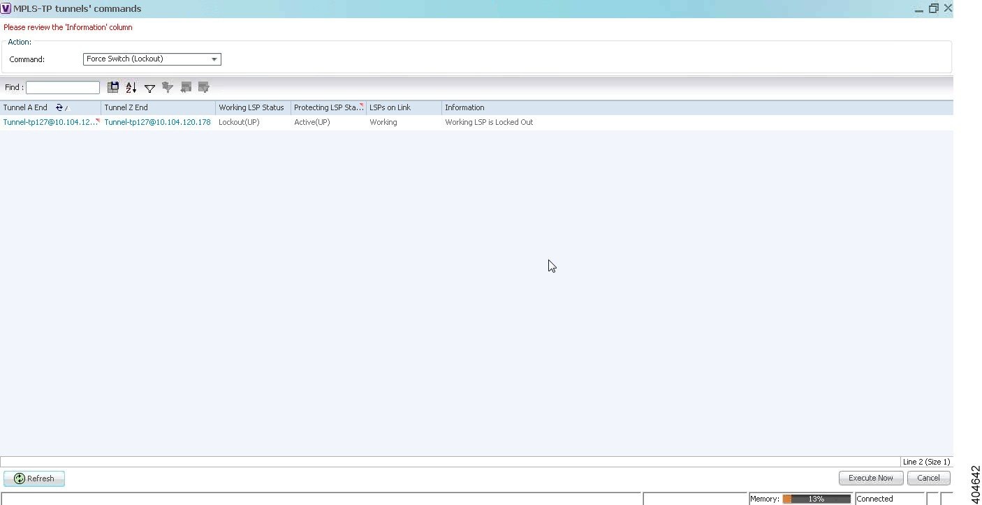
Figure 17-27 Viewing the Commands for Eligible LSPs
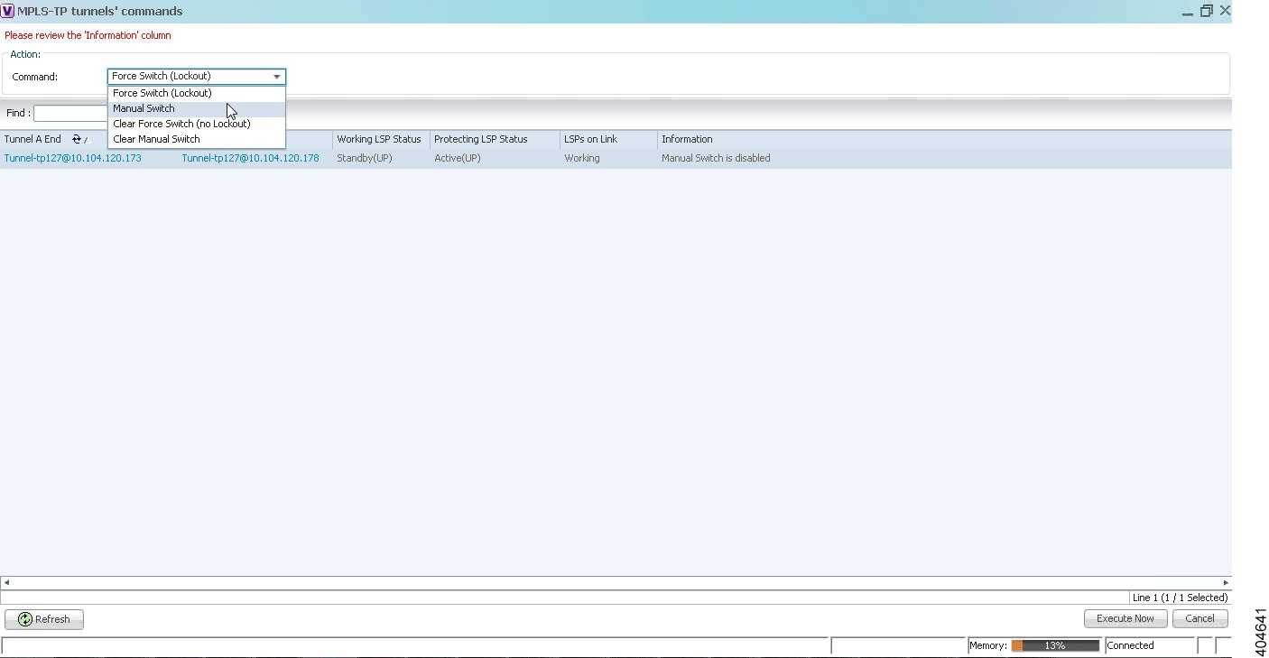
In the above Figure 17-27 the commands that are executed on LSPs on the link are displayed.
It will be enabled only when an eligible LSP is working/protected on the link.
Other Descriptions displayed in the Information Column are :
- If only the Working LSP is configured, you will not be allowed to Lock the Working LSP since, there is no Protected member to carry the traffic; the information column displays the value as Protected LSP is not configured.
- If both the “Working LSP EndPoints” and “Protected LSP EndPoints” are configured in the same physical link, which informs that this tunnel will not be allowed for performing the Lockout operations; the information column displays the value as Both LSPs are configured on the same physical link.
- If the device's Software Version in which the “Manual Switch” feature is disabled; the information column displays the value as Manual switch is disabled.
- If both the Working (Active) and Protected LSPs are in Down state; the information column displays the value as Working and protected LSPs are down.
- If the tunnel is not eligible for any Linear Protection operations as it is disabled, the information column displays the value as Linear Protection is disabled.
Configuring MPLS-TE
The following table lists commands you can use to configure MPLS-TE and how to launch these commands. You can preview a command before executing it, or schedule it to run at a later time. You may be prompted to enter your device access credentials while executing a command.
Your permissions determine whether you can run these commands (see Permissions for Managing MPLS Services). To find out if a device supports these commands, see the Cisco Prime Network 5.1 Supported Cisco VNEs. (You can also add support for new commands by downloading and installing Prime Network Device Packages (DPs); see the Cisco Prime Network 5.1 Administrator Guide.)
Configuring MPLS
The following table lists commands you can use to configure MPLS and how to launch these commands. You can preview a command before executing it, or schedule it to run at a later time. You may be prompted to enter your device access credentials while executing a command.
Your permissions determine whether you can run these commands (see Permissions for Managing MPLS Services). To find out if a device supports these commands, see the Cisco Prime Network 5.1 Supported Cisco VNEs. (You can also add support for new commands by downloading and installing Prime Network Device Packages (DPs); see the Cisco Prime Network 5.1 Administrator Guide.)
Configuring RSVP
The following RSVP commands manage a reserved-bandwidth path between hosts or the end systems to predetermine and ensure Quality of Service (QoS) for their data transmission. You can preview a command before executing it, or schedule it to run at a later time. You may be prompted to enter your device access credentials while executing a command.
Your permissions determine whether you can run these commands (see Permissions for Vision Client NE-Related Operations). To find out if a device supports these commands, see the Cisco Prime Network 5.1 Supported Cisco VNEs. (You can also add support for new commands by downloading and installing Prime Network Device Packages (DPs); see the Cisco Prime Network 5.1 Administrator Guide.)
Configuring BGP
The following BGP commands configure the routing protocol to communicate with the other sites and VRFs. BGP neighbors should be configured as part of BGP routing. At least one neighbor and at least one address family must be configured to enable BGP routing.
You can preview a command before executing it, or schedule it to run at a later time. You may be prompted to enter your device access credentials while executing a command.
Your permissions determine whether you can run these commands (see Permissions for Vision Client NE-Related Operations). To find out if a device supports these commands, see the Cisco Prime Network 5.1 Supported Cisco VNEs. (You can also add support for new commands by downloading and installing Prime Network Device Packages (DPs); see the Cisco Prime Network 5.1 Administrator Guide.)
Configuring VRRP
The following VRRP commands configure the VRRP protocol on routers. These commands configures transparent failover at the first-hop IP router, enabling a group of routers to form a single virtual router. You can preview a command before executing it, or schedule it to run at a later time. You may be prompted to enter your device access credentials while executing a command.
Your permissions determine whether you can run these commands (see Permissions for Vision Client NE-Related Operations). To find out if a device supports these commands, see the Cisco Prime Network 5.1 Supported Cisco VNEs. (You can also add support for new commands by downloading and installing Prime Network Device Packages (DPs); see the Cisco Prime Network 5.1 Administrator Guide.)
Configuring Bundle Ethernet
Configure a bundle of one or more ports to form a single link using bundle ethernet commands.
The following table lists the supported bundle ethernet commands. You can preview a command before executing it, or schedule it to run at a later time. You may be prompted to enter your device access credentials while executing a command.
Your permissions determine whether you can run these commands (see Appendix B, “Permissions Required to Perform Tasks Using the Prime Network Clients” ). To find out if a device supports these commands, see the Cisco Prime Network 5.1 Supported Cisco VNEs. (You can also add support for new commands by downloading and installing Prime Network Device Packages (DPs); see the Cisco Prime Network 5.1 Administrator Guide.)
Viewing MPLS LDP, Static Information
The Multi-Protocol Label Switching (MPLS) is a scalable, protocol-independent transport. In an MPLS network, data packets are assigned labels. The packet-forwarding decisions are made solely based on the contents of this label, without the need of examining the packet itself. This enables creating end-to-end circuits across any type of transport medium using any protocol.
Multiprotocol Label Switching (MPLS) Label Distribution Protocol (LDP) enables peer label switch routers (LSRs) in an MPLS network to exchange label binding information for supporting hop-by-hop forwarding in an MPLS network.
As part of the topological link support, Prime Network started supporting two new service alarms MPLS Link down and MPLS Link up, besides MPLS-TP inventory information. These alarms are raised on the MPLS links during misconfigurations of physical links or shut down of physical interfaces. To view the service alarms supported by Prime Network, refer Cisco Prime Network Supported Service Alarms
Figure 17-28 Viewing MPLS link configured with LDP and Static
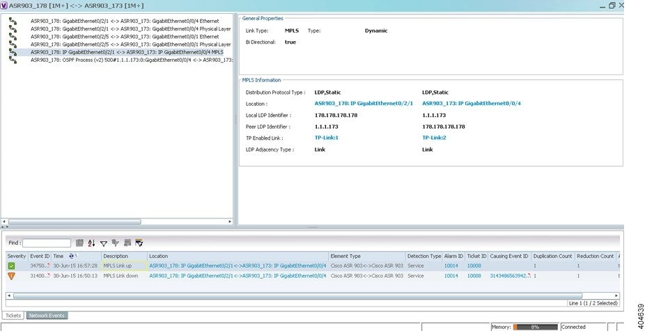
Working with FEC 129-based Pseudowire
The following topics describe how to use the Vision client to monitor FEC 129-based pseudowires:
- FEC 129-based Pseudowire
- Viewing FEC 129-based Pseudowire from Logical Inventory
- Viewing FEC 129 links from Topology View
- FEC 129-based Pseudowire Service Discovery
- Viewing FEC 129 Type II-based Pseudowire Tunnel from Pseudowire Map View
- Viewing FEC 129 Type II-based Pseudowire Tunnels from Virtual Connection Map View
- Viewing FEC 129 Type I-based Pseudowire Tunnel from VPLS Map view
- Viewing FEC 129 Type I-based Pseudowire Tunnels from Virtual Connection Map View
FEC 129-based Pseudowire
A pseudowire (PW) is a Layer 2 circuit or a service that emulates the essential attributes of a telecommunication service (such as T1 line) over an MPLS packet-switched network (PSN).
Pseudowires can be established between two provider edges (PEs) as a single segment (SS) or multisegment (MS) pseudowire.
The Cisco Prime Network supports FEC 129 pseudowire configured in a single segment mode.
The single segment pseudowire (SS-PW) pseudowire originates and terminates on the edge of the same MPLS PSN, especially within the same autonomous system (AS). The pseudowire label is unchanged between the originating and terminating provider edge (T-PE) devices.
The FEC 129 pseudowire uses Source Attachment Individual Identifier (SAII), Target Attachment Individual Identifier (TAII), and Attachment Group Identifier (AGI) to make a key along with the existing attributes such as tunnel ID and peer router IP.
The FEC 129-based pseudowire can be classified into two types based on the attachment circuit:
- Type I—The attachment circuit for type I would be VSI, which in turn connected to bridges on either ends. You can identify the Type I pseudowires uniquely with the AGI, SAII, and TAII values.
- Type II—The attachment circuit for type II would be Ethernet on which EFP is configured. You can identify the Type II pseudowire uniquely with the SAII and TAII values.
In order to configure FEC 129 Type II pseudowire, an Ethernet interface with EFP already configured, is selected. Under this Ethernet interface (which becomes SAII), you can configure the TAII with the target attachment identifier statement. If the configured target identifier matches a source identifier advertised by a remote PE device by way of a BGP auto discovery message, then the pseudowire between that source and target pair is signaled. If there is no match between an advertised source identifier and the configured target identifier, the pseudowire is not established.
The following topic explain how to view the FEC 129 pseudowire from the inventory view:
Viewing FEC 129-based Pseudowire from Logical Inventory
To view the FEC 129-based pseudowire information in the logical inventory:
Step 1![]() Right-click the required device in the Vision client and choose Inventory.
Right-click the required device in the Vision client and choose Inventory.
Step 2![]() In the Inventory window, choose Logical Inventory > Pseudowires.
In the Inventory window, choose Logical Inventory > Pseudowires.
Note![]() The AGI, SAII, and TAII are the new attributes supported for the FEC 129-based pseudowires.
The AGI, SAII, and TAII are the new attributes supported for the FEC 129-based pseudowires.
The Pseudowire Tunnel Edges table is displayed and contains the information described in Table 17-30 .
Viewing FEC 129 Type I-based Pseudowire from VSI Inventory
To view the FEC 129 Type I-based pseudowire from VSI logical inventory:
Step 1![]() To view VSI properties in the Vision client, open the VSI Properties window in either of the following ways:
To view VSI properties in the Vision client, open the VSI Properties window in either of the following ways:
- Double-click the required VNE and, in the Inventory window, choose Logical Inventory > VSIs > vsi.
- In the navigation pane, expand the VPLS instance, right-click the required VPLS forward, and choose Inventory or Properties.
Table 17-31 describes the information that is displayed for the selected VSI.
Note![]() The AGI, SAII, and TAII are the new attributes supported for the FEC 129 pseudowires.
The AGI, SAII, and TAII are the new attributes supported for the FEC 129 pseudowires.
Viewing FEC 129 links from Topology View
Viewing FEC 129 Pseudowire Properties from Topology View
On adding the two associated VNEs to the map, a link is formed between them. This is the topology view and this link depicts the logical association between the associated VNES. Hovering over this link displays all the logical links (or protocols) configured between these peers.
Step 1![]() In the Vision client map view, select a link connected to two devices and open the link quick view window.
In the Vision client map view, select a link connected to two devices and open the link quick view window.
Step 2![]() Click the link between the two VNEs. Identify the FEC 129 pseudowires based on the unique identifiers as mentioned in the Viewing FEC 129-based Pseudowire from Logical Inventory.
Click the link between the two VNEs. Identify the FEC 129 pseudowires based on the unique identifiers as mentioned in the Viewing FEC 129-based Pseudowire from Logical Inventory.
Note![]() If the link is down, it will be displayed in Red and the active links are displayed as green.
If the link is down, it will be displayed in Red and the active links are displayed as green.
Step 3![]() To view the FEC 129 properties in detail, click Properties in the link properties window.
To view the FEC 129 properties in detail, click Properties in the link properties window.
Step 4![]() Select the FEC 129 Type I or II link and the link properties are displayed.
Select the FEC 129 Type I or II link and the link properties are displayed.
Table 17-32 describes the information that is displayed for the FEC 129 link.
FEC 129-based Pseudowire Service Discovery
The Cisco Prime Network delivers FEC 129-based discovery for various support services such as bridge domains, pseudowires, Virtual Connections, and VPLS.
The Cisco Prime Network release supports the following service discoveries:
- Bridge Domain Discovery—Discovers bridges domains such as I-Bridges, B-Bridges, and regular bridges that are not associated to VFIs or pseudowires. For more information, refer to Working with PBB-VPLS.
- Pseudowire Discovery—Discovers pseudowires in any one of the following ways:
–![]() Pseudowires that are associated to I-Bridges and B-Bridges in addition to regular bridges.
Pseudowires that are associated to I-Bridges and B-Bridges in addition to regular bridges.
Note![]() As specified in the Bridge Domain discovery, the regular bridges associated to pseudowires, cannot be discovered from the Bridge Domain services.
As specified in the Bridge Domain discovery, the regular bridges associated to pseudowires, cannot be discovered from the Bridge Domain services.
–![]() All the pseudowires that are associated to Ethernet such as FEC 128, FEC 129 Type II, which in turn has an EFP configured. This service discovers the end-to-end pseudowire peers (FEC 128 or FEC 129 Type II) along with the Ethernet attachments.
All the pseudowires that are associated to Ethernet such as FEC 128, FEC 129 Type II, which in turn has an EFP configured. This service discovers the end-to-end pseudowire peers (FEC 128 or FEC 129 Type II) along with the Ethernet attachments.
Note![]() The FEC 129 Type II end-to-end tunnels are identified from the Pseudowire service using the SAII and TAII values.
The FEC 129 Type II end-to-end tunnels are identified from the Pseudowire service using the SAII and TAII values.
–![]() VFIs associated to I-Bridges, B-Bridges, and regular bridges.
VFIs associated to I-Bridges, B-Bridges, and regular bridges.
Note![]() As specified in the Bridge Domain discovery, the regular bridges associated to VFIs, cannot be discovered from the Bridge Domain services.
As specified in the Bridge Domain discovery, the regular bridges associated to VFIs, cannot be discovered from the Bridge Domain services.
–![]() VFIs associated to pseudowires such as FEC 128, FEC 129 Type I pseudowires (pseudowires which are attached to VFIs which in turn attached to bridges (B-Bridges)) are discovered. This service discovers the end-to-end VFIs, which on expanding from the VPLS map view, displays the end-to-end pseudowire peers (FEC 128 or FEC 129 type I pseudowires).
VFIs associated to pseudowires such as FEC 128, FEC 129 Type I pseudowires (pseudowires which are attached to VFIs which in turn attached to bridges (B-Bridges)) are discovered. This service discovers the end-to-end VFIs, which on expanding from the VPLS map view, displays the end-to-end pseudowire peers (FEC 128 or FEC 129 type I pseudowires).
Note![]() The FEC 129 Type I end-to-end tunnels are identified from the VPLS service using the Attachment Group Identifier (AGI) value along with SAII and TAII values.
The FEC 129 Type I end-to-end tunnels are identified from the VPLS service using the Attachment Group Identifier (AGI) value along with SAII and TAII values.
Note![]() In order to view the B-bridges attached to the VFIs, the bridges must be selected from the Bridge Domain service.
In order to view the B-bridges attached to the VFIs, the bridges must be selected from the Bridge Domain service.
- Virtual Connection or EVC Discovery—Creates an end-to-end complex circuit representing the network associations in the core network of all the above discovered elements. Using the Virtual Connection map view, the complete topology of the pseudowire is displayed instead of selecting each plugin separately from the VPLS or pseudowire map view.
–![]() FEC 129 Type I—Instead of selecting FEC 129 Type I pseudowires and their associated VFIs (from the VPLS service) and the associated B-bridges (from the bridge domain service), the FEC-129 type 1 end-to-end tunnels can be viewed as a single instance from the Virtual Connection service.
FEC 129 Type I—Instead of selecting FEC 129 Type I pseudowires and their associated VFIs (from the VPLS service) and the associated B-bridges (from the bridge domain service), the FEC-129 type 1 end-to-end tunnels can be viewed as a single instance from the Virtual Connection service.
The FEC 129 Type I end-to-end tunnels are identified using the AGI value along with SAII and TAII values.
–![]() FEC 129 Type II—The FEC 129 Type II end-to-end tunnels and the Ethernet attachments can be viewed as a single instance from the Virtual Connections service.
FEC 129 Type II—The FEC 129 Type II end-to-end tunnels and the Ethernet attachments can be viewed as a single instance from the Virtual Connections service.
The FEC 129 Type II end-to-end tunnels are identified using the SAII and TAII values.
The following topics explain how to view the FEC 129-based pseudowire from service discovery:
- Viewing FEC 129 Type II-based Pseudowire Tunnel from Pseudowire Map View
- Viewing FEC 129 Type II-based Pseudowire Tunnels from Virtual Connection Map View
- Viewing FEC 129 Type I-based Pseudowire Tunnel from VPLS Map view
- Viewing FEC 129 Type I-based Pseudowire Tunnels from Virtual Connection Map View
Viewing FEC 129 Type II-based Pseudowire Tunnel from Pseudowire Map View
To discover the links between the FEC Type II pseudowires:
Step 1![]() Choose Add to Map > Pseudowire to open the Add Pseudowire to Specific plugins dialog box.
Choose Add to Map > Pseudowire to open the Add Pseudowire to Specific plugins dialog box.
Step 2![]() In the Add Pseudowire to Specific plugins dialog box, select Show All to display the list of pseudowires.
In the Add Pseudowire to Specific plugins dialog box, select Show All to display the list of pseudowires.
Step 3![]() To view a specific FEC Type II pseudowire, filter using the pseudowire ID (SAII or TAII) to identify the FEC Type II pseudowire.
To view a specific FEC Type II pseudowire, filter using the pseudowire ID (SAII or TAII) to identify the FEC Type II pseudowire.
Step 4![]() Click OK to add the selected FEC 129 type II pseudowire to the map.
Click OK to add the selected FEC 129 type II pseudowire to the map.
Step 5![]() The selected pseudowire component in the map displays the following links. Click the expand (+) icon to view the links:
The selected pseudowire component in the map displays the following links. Click the expand (+) icon to view the links:
- Association between the EFP of one router (for example, router 1) to the FEC 129 type II pseudowire.
- Link between the two associated FEC 129 type II pseudowires that are peers.
- Association between the FEC 129 type II pseudowire of the other router (for example, router 2) to the EFP.
Viewing FEC 129 Type II-based Pseudowire Tunnels from Virtual Connection Map View
The Virtual Connection view displays the logical association between the FEC 129 type II pseudowires in a single view.
To view the end-to-end connection between the FEC 129 type II pseudowire peers:
Step 1![]() Open the Add Virtual Connection to Specific plugin dialog box in either of the following ways:
Open the Add Virtual Connection to Specific plugin dialog box in either of the following ways:
Step 2![]() In the Add Virtual Connection to Specific plugins dialog box, select the virtual connection that you want to view.
In the Add Virtual Connection to Specific plugins dialog box, select the virtual connection that you want to view.
Step 3![]() To view a specific FEC type II pseudowire, filter using the pseudowire ID (SAII or TAII) to identify the FEC Type II pseudowire.
To view a specific FEC type II pseudowire, filter using the pseudowire ID (SAII or TAII) to identify the FEC Type II pseudowire.
Step 4![]() Click OK to add the selected virtual connection component to the map.
Click OK to add the selected virtual connection component to the map.
Step 5![]() For the selected virtual connection component in the map, you can view the following FEC 129 Type II pseudowire information:
For the selected virtual connection component in the map, you can view the following FEC 129 Type II pseudowire information:
- Viewing FEC 129 Type II Pseudowire Links from Virtual Connection View
- Viewing FEC 129 Type II Pseudowire Properties from Virtual Connection View
Viewing FEC 129 Type II Pseudowire Links from Virtual Connection View
To view the end-to-end connection between the FEC 129 type II pseudowire peers:
Step 1![]() Click the expand (+) icon to view the links:
Click the expand (+) icon to view the links:
- Association between the EFP of one router (for example, router 1) to the FEC 129 type II pseudowire.
- Link between the two associated FEC 129 type II pseudowires that are peers.
- Association between the FEC 129 type II pseudowire of the other router (for example, router 2) to the EFP.
Viewing FEC 129 Type II Pseudowire Properties from Virtual Connection View
To view the FEC 129 type II pseudowire properties:
Step 1![]() Right-click the selected virtual connection component in the map.
Right-click the selected virtual connection component in the map.
Step 2![]() Click the Properties tab to display the EVC hyperlink.
Click the Properties tab to display the EVC hyperlink.
Step 3![]() Click the EVC hyperlink to view the EVC terminating points.
Click the EVC hyperlink to view the EVC terminating points.
Viewing FEC 129 Type I-based Pseudowire Tunnel from VPLS Map view
The FEC 129 Type I pseudowires are associated to VFIs, which in turn are associated to PBB bridges (that is VFIs are attached to B-bridges, and B-bridges are attached to I-bridges on both the FEC 129 Type I pseudowire peers).
The following services help in viewing the components involved in forming the FEC 129 Type I-based pseudowire topology:
- VPLS view—You can view the FEC 129 Type I pseudowires that are attached to the VFIs from the VPLS view. These VFIs are in turn attached to the PBB bridges. To view the VFIs, refer Viewing VPLS.
- Bridge Domain view—From the bridge domains service, you can view the PBB bridges (I-bridges linked to the B-bridges). To view the bridge domains, refer Viewing Bridge domains.
Note![]() In addition to PBB bridges, regular bridges, with no associations to pseudowires or VFIs, can also be discovered in the Bridge Domain service.
In addition to PBB bridges, regular bridges, with no associations to pseudowires or VFIs, can also be discovered in the Bridge Domain service.
Viewing VPLS
Step 1![]() Choose Add to Map > VPLS to open the Add VPLS Instance to map dialog box.
Choose Add to Map > VPLS to open the Add VPLS Instance to map dialog box.
Step 2![]() In the Add VPLS Instance to map dialog box, select Show All to display the list of VPLS instances.
In the Add VPLS Instance to map dialog box, select Show All to display the list of VPLS instances.
Step 3![]() Add the required VPLS instance from the VPLS list. It can be filtered either using the VPN-id or the names of the associated VFIs.
Add the required VPLS instance from the VPLS list. It can be filtered either using the VPN-id or the names of the associated VFIs.
Step 4![]() Once the VPLS instance is added to the map, it displays the link between the two associated VFIs. On further expanding these VFI components, you can view the associated FEC 129 Type 1 pseudowire peers, linked to these VFIs on either ends.
Once the VPLS instance is added to the map, it displays the link between the two associated VFIs. On further expanding these VFI components, you can view the associated FEC 129 Type 1 pseudowire peers, linked to these VFIs on either ends.
Step 5![]() Click the link between the two associated FEC 129 Type 1 pseudowire peers to display the topology link properties window. This link is specific to these FEC 129 Type 1 pseudowire peers.
Click the link between the two associated FEC 129 Type 1 pseudowire peers to display the topology link properties window. This link is specific to these FEC 129 Type 1 pseudowire peers.
Unlike the Map view, topology properties which display all the topology links between the two VNEs are added to the map. Refer Viewing FEC 129 links from Topology View.
Viewing Bridge domains
To view the bridge domains associated to the VFIs, follow the steps provided below:
Step 1![]() Open the Add Bridge Domain dialog box in one of the following ways:
Open the Add Bridge Domain dialog box in one of the following ways:
Note![]() The Bridge Domains must be added to the map containing the VPLS instances to view the associations between them.
The Bridge Domains must be added to the map containing the VPLS instances to view the associations between them.
Step 2![]() In the Add Bridge Domain dialog box, select Show All to display the list of bridge domains.
In the Add Bridge Domain dialog box, select Show All to display the list of bridge domains.
Step 3![]() For both the peers, select the PBB bridges associated to the VFIs. The bridges can be filtered using the name of the bridges.
For both the peers, select the PBB bridges associated to the VFIs. The bridges can be filtered using the name of the bridges.
Note![]() I-SID can also be used for filtering I-bridges.
I-SID can also be used for filtering I-bridges.
Step 4![]() On adding the PBB-bridges to the map:
On adding the PBB-bridges to the map:
- A link is formed between the associated VPLS plugin and the B-bridges for both the peers.
- A link is formed between the I-bridges and the B-bridges for both the peers.
Viewing FEC 129 Type I-based Pseudowire Tunnels from Virtual Connection Map View
The Virtual Connection view displays the logical association between the FEC 129 type I pseudowire peers in a single view.
To view the end-to-end connection between the FEC 129 type I pseudowire peers:
Step 1![]() Open the Add Virtual Connection to Specific plugin dialog box in either of the following ways:
Open the Add Virtual Connection to Specific plugin dialog box in either of the following ways:
Step 2![]() In the Add Virtual Connection to Specific plugins dialog box, select the FEC 129 type I-based pseudowire virtual connection that you want to view.
In the Add Virtual Connection to Specific plugins dialog box, select the FEC 129 type I-based pseudowire virtual connection that you want to view.
Step 3![]() To view a specific FEC type I pseudowire, filter using the I-SID, VPN-id, or the names of the associated VFIs to identify the FEC Type I pseudowire.
To view a specific FEC type I pseudowire, filter using the I-SID, VPN-id, or the names of the associated VFIs to identify the FEC Type I pseudowire.
Step 4![]() Click OK to add the selected virtual connection component to the map.
Click OK to add the selected virtual connection component to the map.
Step 5![]() You can view the following FEC 129 Type I pseudowire information for the selected virtual connection component added to the map:
You can view the following FEC 129 Type I pseudowire information for the selected virtual connection component added to the map:
- Viewing FEC 129 Type I Pseudowire Links from Virtual Connection View
- Viewing FEC 129 Type I Pseudowire Properties from Virtual Connection View
Viewing FEC 129 Type I Pseudowire Links from Virtual Connection View
To view the end-to-end connection between the FEC 129 Type I-based pseudowire peers:
Step 1![]() Click the Expand (+) icon to view the associated components and the links:
Click the Expand (+) icon to view the associated components and the links:
- Association between the VPLS instances. Click the Expand (+) icon on the VPLS instances.
- Association between the VFIs, which on further expansion, displays the corresponding components.
- Association between the FEC-129 Type I-based pseudowire peers. To view the topology Link Properties window, click the link between the two associated FEC 129 Type I-based pseudowire peers.
If the above topology has PBB bridges configured on either ends, then the following are displayed in addition to the above components and links:
- Association between the I-bridges and the B- bridges (of both the FEC 129 Type I pseudowire peers).
- Association between the B-bridges and the VPLS instances. For further viewing the components attached to the VPLS instances, navigate to Step 1.
Viewing FEC 129 Type I Pseudowire Properties from Virtual Connection View
To view the virtual connection properties of FEC 129 type I pseudowire peers:
Step 1![]() Right-click the selected virtual connection component in the map.
Right-click the selected virtual connection component in the map.
Step 2![]() Click the Properties tab to display the EVC hyperlink.
Click the Properties tab to display the EVC hyperlink.
Step 3![]() Click the EVC hyperlink to view the EVC terminating points.
Click the EVC hyperlink to view the EVC terminating points.
 Feedback