Provision Circuits/VCs

Provision Circuits/VCs in Cisco EPN Manager

The process of creating and provisioning a circuit/VC is similar for all the supported technologies and involves:
  • Specifying the endpoints of the circuit/VC.

  • Defining the configuration parameters of the circuit/VC.

For a detailed overview of the provisioning support in Cisco EPN Manager, see Provision Circuits/VCs.

To create and provision a new circuit/VC:

Procedure


Step 1

From the left sidebar, choose Maps > Topology Maps > Network Topology.

Step 2

Click on the Device Groups button, select the required device group(s) and click Load.

Step 3

Close the Device Groups popup window.

Step 4

In the Network Topology window, click the Circuits/VCs tab.

Step 5

Click the '+' icon to open the Provisioning Wizard in a new pane to the right of the map.

Note 

You can also access the Provisioning wizard by choosing Configuration > Network > Service Provisioning

Step 6

From the Technology drop-down list, choose the required technology. For example, if you are creating a circuit for Optical/DWDM network, choose Optical.

Step 7

In the Service Type area, choose the type of circuit/VC you want to create. For example, if you are creating a circuit/VC for Optical/DWDM network, the various circuit types include OCHNC WSON, OCHCC WSON, OCH-Trail WSON, OCH-Trail UNI, ODU UNI, ODU Tunnel and OPU over ODU.

Step 8

If you have defined profiles to set the attributes of the different services, select the required profile from the Select Profile drop-down list. See Create Circuit/VC Profiles.

Step 9

Click Next to go to the Customer Service Details page.

Step 10

(Optional) Select the customer for whom the circuit/VC is being created. If there are no customers in the list, go to Inventory > Other > Customers to create the customer in the system, and then go to the Provisioning Wizard to start provisioning the circuit/VC.

Step 11

Enter the service name and its description.

Step 12

From the Deployment Action drop-down list, choose the action that you want to perform after defining the attributes for the circuit/VC. The options are:

  • Preview—Displays the generated CLIs for each device. You can review the CLIs and decide if you want to edit any attributes or go ahead with the deployment.

  • Deploy—Deploys the configuration to the relevant devices immediately after you click Submit in the last page of the Provisioning Wizard.

    Click one of the following deployment options:

    • Deploy Now—Directly deploys the provisioning order

    • Deploy Later—Saves the created provisioning order.You can deploy the same order at later point of time.To redeploy the provisioning order click the circuit/VCs link at the bottom of the left pane.

    • Schedule Deployment—Saves the order for future deployment at the designated time provided by you. Schedules the provisioning order and creates the Job order to be deployed at the scheduled time. If required, you can specify the date and time to provision the order in the Job Scheduler.dialog box.

      If you click this Schedule Deployment radio button, specify the following:

      • Deploy Schedule Time—Specify a schedule time for deployment of provision order.

      • Server Time—Displays the current server time.

    To know more about how to schedule and save a provisioning order, see Save and Schedule a Provisioning Order

Step 13

Click Next to choose the endpoints and define the attributes based on the technology you have selected.

Step 14

Click Submit. Depending on the deployment action you have chosen, the relevant action will be performed. That is, if you have chosen to preview the configuration, the preview page will be displayed where you can view the configurations, and then click Deploy. If you have chosen to deploy, the configurations will be directly deployed to the relevant devices.

Step 15

(Optional) Click the Leave this View button to continue using Cisco EPN Manager and to enable the service deployment to continue in the background.

Note 

If the device is busy, the request from Cisco EPN Manager to deploy the service will wait up to a pre-configured period of time before the request times out. To change this setting, see Set the Service Deployment Timeout Value.


The circuit/VC should be added to the list in the Circuits/VCs pane in the Network Topology window. To check the provisioning state, click the i icon next to the circuit/VC name to see the Circuit/VC 360 view.
For information about how to create and provision circuit/VCs for various technologies, see:

You can view the saved provisioning order in the Planned Circuits/VCs tab from Administration > Dashboards > Job Dashboard > Provisioning.

Click the (I) icon at the Last run stat field and view the configuration and Device details.

Set the Service Deployment Timeout Value

When you deploy a service to devices, if the devices are pre-occupied or busy, the service request created waits for a pre-configured period of time to acquire a ‘device lock’ for deploying the service. By default, the timeout value is set to 60 minutes.

To change the default timeout value:

Procedure


Step 1

From the left sidebar, choose Administration > Settings > System Settings .

Step 2

Expand the Circuits/VCs section and click Deployment Settings.

Step 3

Set the required timeout value in minutes.

Cisco EPN Manager will now wait up to the specified time period to acquire the device lock for deploying the service. If the lock is not acquired within this time, the service deploy operation will fail.


Set the Circuit Activation Wait Timeout Value

You can configure the maximum time interval for which the provisioning system waits until circuit activation wait timeout.

Procedure


Step 1

From the left sidebar, choose Administration > Settings > System Settings .

Step 2

Expand the Circuits/VCs section and click Deployment Settings.

Step 3

Set the required timeout value in minutes in the Circuit Activation Wait Timeout field.

By default, the timeout is 5 minutes.


Configure to Auto Delete WSON/SSON Circuits

You can enable the option to auto delete the NCS2K TL1 based WSON/SSON circuits that EPNM manages. If the circuits are deleted from other devices or CTC, it is also deleted from EPNM. To configure auto delete WSON/SSON circuits:

Procedure


Step 1

From the left sidebar, choose Administration > Settings > System Settings .

Step 2

Expand the Circuits/VCs section and click Deployment Settings.

Step 3

Check the Auto detect WSON/SSON circuits check box.


What Happens When a Deployment Fails

When you deploy a circuit/VC, Cisco EPN Manager performs configuration changes in the participating devices based on the type of circuit/VC. Only when the configuration changes are successfully deployed to the devices, the circuit/VC will be considered as successfully provisioned. If the deployment of configuration changes fails in any one of the participating device, Cisco EPN Manager rolls back the configuration changes made so far in all the devices.

If the deployment of configuration changes fails in any one of the participating device, you can click Redeploy on the provisioning wizard. The redeploy action reattempts the deployment with the same configuration.


Note

Redeploy button is supported for OCHNC WSON, OCHCC WSON, OCHCC, OCH-Trail WSON, OCH-Trail, Media Channel NC SSON, Media Channel Trail SSON, Media Channel CC SSON optical circuits.


Deployment action can result in any one of the following scenarios:
  • Deployment succeeds in all the participating devices; roll back is not initiated—In this scenario, all devices are successfully configured and the circuit provisioning is successful.

  • Deployment fails; roll back is initiated and succeeds—In this scenario, when configuring multiple devices, the configuration fails in one of the device. The failure could be due to various reasons, for example, the device has declined the configuration. Cisco EPN Manager identifies the failure and successfully rolls back all the configuration changes that were made on all the devices. In this scenario, all device configurations are restored to the states, which were there before the deployment was attempted.

    Here is an example with three devices, A, B, and C, which are configured in a sequential order to provision a circuit. The configuration changes are deployed successfully in device A, but the deployment fails in device B. Cisco EPN Manager detects the failure and stops further configuration in devices B and C. It rolls back the configuration in the reverse order of provisioning, that is, it first rolls back the device B, followed by device A. Following are the actions that are performed sequentially in the three devices:

    • Device C—Rollback is not required for device C because there were no changes deployed to the device. This is because the configuration failure was detected in device B before configurations changes were sent to device C.

    • Device B—Cisco EPN Manager checks if there are any configuration changes made on this device before the deployment failed. If there are any changes, the partial configuration on this device is removed and the device is rolled back to the previous configuration.

    • Device A—Cisco EPN Manager performs a complete roll back in device A, where all the configuration changes that were successfully deployed earlier are removed and the device is rolled back to the previous configuration.

  • Deployment fails; roll back is initiated but fails— In this scenario, when the configuration deployment fails on any of the participating device(s), Cisco EPN Manager performs a rollback, but the rollback on one or more devices fail. Now, the device(s) on which the roll back had failed, has the partial configuration.

    For example, the configuration changes are successfully deployed in devices A and B, the deployment fails in device C. Cisco EPN Manager identifies the failure and initiates the rollback in the reverse order of provisioning, that is, it first rolls back the device C, device B, and then device A. Following are the actions that are performed sequentially in the three devices:

    • Device C—Cisco EPN Manager performs a successful rollback in device C.

    • Device B—When attempting a rollback on device B, device connectivity is lost and there could be partial configurations left on the device.

    • Device A—Cisco EPN Manager performs a rollback of Device A, even if the roll back fails in device B.


Note

The rollback may fail due to various other reasons.


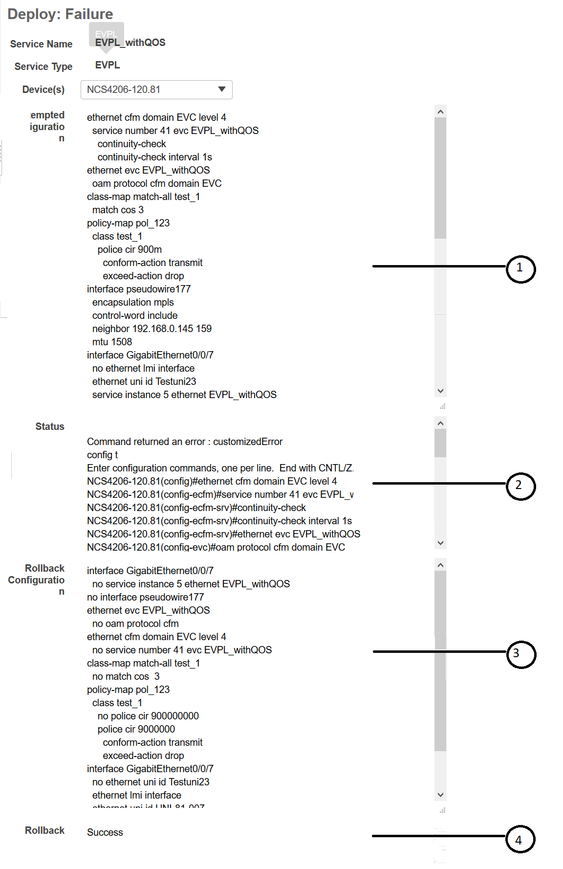
In the Provisioning Wizard, after previewing the configurations, click Deploy. When the deployment fails, the rollback configuration and the status for each participating device is displayed. From the Device(s) drop-down list, choose the device for which you want to view the rollback configuration and the status.

The following figure illustrates the rollback configuration and the rollback status for each device.

1

Attempted Configuration— Shows the configurations that were deployed to the device selected in the Device(s) drop-down list.

2

Deployment Status— Shows the deployment status of the selected device. If the deployment succeeds, it shows the status as "Success". If the deployment fails, it provides information about the failure.

3

Roll back Configuration— Shows the configurations for which rollback is automatically attempted.

4

Roll back Status— Shows the rollback status of the selected device. If the rollback succeeds, it shows the status as "Success". If the rollback fails, it provides information about the failure. You can use this information to manually clean up the partial configurations on the device.

You can also delete the failed deployments from this window by clicking Delete.

You can also click the i icon next to the Provisioning column in the Circuits/VCs and Deleted Circuits/VCs tabs in the extended tables to view the details of configuration, configuration errors, rollback configuration, and rollback configuration errors for each device participating in the circuit/VC. The i icon is available for all provisioning states, except None. For information about how to access the extended tables, see View Detailed Tables of Alarms, Network Interfaces, Circuits/VCs, and Links from a Network Topology Map.

For information about how to troubleshoot deployment and rollback failures, see Troubleshoot Configuration Deployment Failures and Roll Back Failures.

Troubleshoot Configuration Deployment Failures and Roll Back Failures

Following are the tips to troubleshoot the deployment or roll back failures:
  • Deployment fails, but roll back succeeds— If the configuration deployment fails, roll back is automatically initiated and the results are displayed in the results page. Analyze the attempted configuration and error message shown in the results page for each device and identify the root cause of the deployment failure.

    The deployment failure could be due to, but not limited to the following issues:
    • Invalid values entered for the service parameters in the Provisioning Wizard. For example, the Service ID may already exists or there could be semantic errors in the CLI that is generated, and so on.

    • Device issues such as, device is not reachable, device password has changed, and so on.

    In this case, you must locate the circuit (by the name that you had given when creating it) for which deployment has failed, edit the circuit, and re-attempt the provisioning. If the service parameter for which the value to be changed is not editable, delete the circuit and create a new circuit.

    Note

    Before deleting the circuit, ensure that it is not in use.


  • Both, deployment and roll back fails— In this case, do the following:
    1. Ensure that the device is reachable and perform a device re-synch.

    2. If there were any device issues that were reported in the previous deployment, try to fix the issues.

    3. Edit the circuit and update the attributes, if required, and then re-attempt the circuit deployment.

    4. If the deployment fails, Cisco EPN Manager will initiate the roll back.

    5. If the roll back fails again, identify the cause of the roll back failure.

    6. To identify the cause of the failure, you can use the configuration and roll back transaction details, history of the service deployment attempts, and the roll back attempts that are displayed in the Circuit/VC 360 view. See Get Quick Information About a Circuit/VC: Circuit/VC 360 View.

    7. Manually remove the partial configurations that are stored on the device.

You can also contact the Cisco representative to analyze and identify the root cause of configuration deployment failure and roll back failure.

WAN Automation Engine Integration

Cisco WAN Automation Engine Integration with Cisco EPN Manager

The Cisco WAN Automation Engine (WAE) platform is an open, programmable framework that interconnects software modules, communicates with the network, and provides APIs to interface with external applications.

Cisco WAE provides the tools to create and maintain a model of the current network through continuous monitoring and analysis of the network and based on traffic demands that are placed on it. This network model contains all relevant information about a network at a given time, including topology, configuration, and traffic information. You can use this information as a basis for analyzing the impact on the network due to changes in traffic demands, paths, node and link failures, network optimizations, or other changes.


Note

For details, refer to the latest Cisco WAN Automation Engine (WAE) Installation Guide and Cisco WAN Automation Engine (WAE) User Guide.


In Cisco EPN Manager, when you create an unidirectional or a Bidirectional tunnel with an explicit path, the WAN Automation Engine (WAE) integration provides you the explicit path using a REST call from Cisco EPN Manager automatically. Thus, you can avoid manually entering the explicit paths. WAE provides you a list of possible network paths to review and allows you to select an appropriate path.

Configure WAE Parameters

To specify the WAE path details:
Before you begin

Ensure to set the WAE parameters:

  1. Choose Administration > Settings > System Settings

  2. Expand Circuit VCs and then choose WAE Server Settings.

  3. Enter the relevant WAE Details (version 7.1.3 and above) and field details such as WAE Server IP, WAE Port Address, WAE Server User Name, and WAE Server Password.

  4. Click Save to save the WAE server settings or click Reset to Defaults to clear all the entries.

Procedure

Step 1

Create a Unidirectional or Bidirectional tunnel with necessary parameters. For more information, see Create and Provision an MPLS TE Tunnel.

Step 2

In the Path Constraints Details area, choose the path type either as Working or Protected. See Field References for Path Constraint Details—MPLS TE Tunnel for descriptions of the fields and attributes.

Step 3

Check the New Path check box if you want to enable the Choose Path from WAE server check box.

Step 4

Check the Choose Path from WAE server checkbox. EPNM manager sends a REST request to WAE to obtain WAE networks.

WAE will return a list of possible networks.
Step 5

From the Select WAE Network drop-down list, choose a network.

EPNM manager will send a REST conf request to WAE with all the required parameters such as Source, Destination, and Network. Max path returned default value = 2; Max Path value is configured through WAE. WAE displays a list of possible paths satisfying the request.
Step 6

From the Select WAE Path drop-down list, choose the appropriate paths returned.

EPNM shows the selected path overlay on the map.
Step 7

Enter the name of the path in the Path Name field.

You can proceed with provisioning the order using the last selected path as explicit path.

Provision EVCs in a Carrier Ethernet Network

Summary of Cisco EPN Manager Carrier Ethernet Provisioning Support

This topic provides a summary of the Carrier Ethernet service provisioning support in Cisco EPN Manager. For a more detailed overview of the different types of EVCs and the supported underlying networks, see Overview of Circuit/VC Discovery and Provisioning.

Cisco EPN Manager supports provisioning of both port-based and VLAN-based VCs of the following types:

Cisco EPN Manager supports the following supplementary provisioning functions that can be used during EVC creation:

  • Provision UNIs—For each EVC, you must define the attributes of the participating UNIs. You can either do this during the EVC creation or you can provision a UNI independently of the EVC creation process. See Configure a Device and Interface To Be a UNI.
  • Provision ENNI—For E-Access circuits, you must define the attributes of the ENNI. You can either do this during the EVC creation or you can provision an ENNI independently of the EVC creation process. See Configure a Device and Interface To Be an ENNI.
  • QoS Profiles—You can create QoS profiles to apply to VCs.
  • EVC Attribute Profiles—You can create profiles containing all the required attributes for an EVC. These profiles can be selected during EVC creation to define the attributes of the EVC, instead of having to define the attributes individually for each EVC. See Create Circuit/VC Profiles.

Prerequisites for EVC Provisioning

The following prerequisites must be met before you can provision EVCs:

  1. Communication between devices must be set up before you can provision EVCs:
    • In an MPLS end-to-end network, Label Distribution Protocol (LDP) must be set up across the network and each device must be provided with an LDP ID. This enables peer label switch routers (LSRs) in an MPLS network to exchange label binding information for supporting hop-by-hop forwarding. Alternatively MPLS end-to-end connectivity can be achieved using MPLS Traffic Engineering or segment routing, and specifically, EVC (only P2P type) provisioning over unidirectional or bidirectional TE tunnels is supported. CEm provisioning over TE tunnels and provisioning over SR policies is also supported.
    • If there is Ethernet access, i.e., not all devices are MPLS-enabled, G.8032 rings or ICCP-SM must be configured to connect the Ethernet access switch to the MPLS switch.
    • CDP or LLDP must be configured on the links within the G.8032 ring to enable Ethernet link discovery.
  2. To provision EVCs over ICCP-SM and G.8032 networks, all VLANs (from 1 to 4095) should be configured either as primary or as secondary VLANs.
  3. Inventory collection status for the devices on which the EVCs will be provisioned must be Completed . To check this, go to Inventory > Network Devices , and look at the status in the Last Inventory Collection Status column.
  4. Customers can be created in the system so that you can associate a circuit/VC to a customer during the circuit/VC creation and provisioning process. Choose Inventory > Other > Customers in the left sidebar to create and manage customers.
  5. For interfaces to be used in EVCs, it is recommended to reset the default configuration on the interfaces. In global configuration mode, configure the following command on each interface:
    
    default interface 'interface-name’
    
  6. For ME3600 and ME3800 devices, service instances can only be configured on trunk ports with no allowed VLANs. Configure the following commands on the interface and then re-sync the device in Cisco EPN Manager:
    interface GigabitEthernetXX/XX
    switchport trunk allowed vlan none
    switchport mode trunk
  7. To provision EPL and EVPN services when using EVPN, define the following command under BGP section in device configuration. If you do not configure this command, the device will not be displayed when you provision a EVPN service.

    
    address-family l2vpn evpn
    

Create and Provision a New Carrier Ethernet EVC

EVCs are created in the context of the topology map. You can access the topology map and the Provisioning Wizard by choosing Configuration > Network > Service Provisioning in the left sidebar or you can open the Provisioning Wizard from the topology map, as described in the procedure below.

The process of creating and provisioning an EVC is similar for all supported EVC types and involves:

  • Specifying the endpoints (UNIs and ENNIs) of the EVC.

  • Defining the configuration parameters of the circuit/VC.

After a service is provisioned, you can edit the service and update or change the A-end or Z-end points.

Endpoint modification is supported with E-line services such as EPL and EVPL. you can modify only managed endpoints and full and partial services.

During modification of service, if existing UNI has different device or same device with different port, you can change to other existing UNI.

Some limitations are:

  • You cannot modify the endpoints on both end in a single modification of services.

  • Create an UNI using the standalone UNI wizard and use it in modification of EPL or EVPL services.

  • During modification of service you cannot create a new UNI.

Before you begin

For information about the prerequisites that must be met before you can provision EVCs, see Prerequisites for EVC Provisioning.

To create a new EVC:

Procedure


Step 1

In the left sidebar, choose Maps > Topology Maps > Network Topology.

Step 2

Click the Device Groups button in the toolbar and select the group of devices you want to show on the map.

Step 3

In the Circuits/VCs tab, click the '+' icon to open the Provisioning Wizard in a new pane to the right of the map.

Step 4

Select Carrier Ethernet in the Technology drop-down list. Cisco EPN Manager displays a list of relevant circuit/VC types in the Service Type area. For example, Carrier Ethernet service types include EPL, EVPL, EP-LAN, and so on.

Step 5

In the Service Type list, select the type of circuit/VC you want to create.

Step 6

If you have defined profiles to set the attributes of the different services, select the required profile from the Select Profile drop-down list. See Create Circuit/VC Profiles.

Step 7

Click Next to go to the Service Details page.

Step 8

(Optional) Select the customer for whom the EVC is being created. If there are no customers in the list, go to Inventory > Other > Customers to create the customer in the system, and then restart the Provisioning Wizard.

Step 9

Enter the Service Details. See Service Details Reference for descriptions of the fields and attributes.

Step 10

For E-Line, E-Tree, and E-LAN EVCs: If required, configure the service OAM which enables fault and performance monitoring across the EVC. For E-Line EVCs, select the Enable CFM check box to enable the Service OAM options. You can then choose to either create a new CFM domain or select an existing domain for the E-Line EVC. See Service OAM. Click the Plus icon to add a row to the Service OAM table and provide values in the relevant columns. For E-Tree EVCs, you must specify the direction, i.e., Leaf-to-Root, Root-to-Leaf, or Root-to-Root.

If you want to promote and reconcile point-to-point services or multipoint services, for example EVPL/EPL services, enable the CFM parameters such as CFM Domain name, CFM Domain level, Maint. Assoc. Name Type, ITU Carrier Code, ITU MEG ID Code and Continuity check interval fields. CFM parameters will be read from the discovered version during service promotion. You can perform reconciliation with discovered or provisioned version.
Note 

By default IEEE is selected as the Maint Assoc Name. If ITU is selected in the Maint. Assoc. Name Type drop down list, ITU Carrier Code and ITU MEG ID code appears.

Step 11

In the Deployment Action field, specify what you want to do when the EVC creation process is completed. You can either request a preview of the configurations that will be deployed to the relevant devices before the actual deployment or you can deploy the configurations immediately upon completion.

Step 12

Click Next to go to the page(s) in which you define the UNI(s). In the case of E-Access, there is an additional page for defining the ENNI.

Step 13

Identify the device and interface that will serve as the UNI:

Note 

If one of the endpoints is an interface on a device that is not managed by Cisco EPN Manager, select the Unmanaged check box and provide information for the unmanaged device. See Provision a Circuit/VC with an Unmanaged Endpoint.

  • If you have already configured the required interface on the device as a UNI, uncheck the Create New UNI check box and select the relevant UNI Name from the list.

    Note 
    The UNI names in the list vary according to the services and the options selected at the time of creating the UNI.
    • For EPL, Access EPL, EP LAN, and EP Tree services, only those UNIs for which the All To One Bundling option was selected at the time of creation will be listed.

    • For EVPL, Access EVPL, and EVP Tree services, only those UNIs for which the Multiplexing or Bundling options or both are selected at the time of creation will be listed.

  • To create a new UNI:

    • Make sure that the Create New UNI check box is checked.

    • In the UNI Name field, enter a name for the UNI that will enable easy identification of the UNI.

    • Select a device from the list in the Device field or click on a device in the map to select it and populate the Device field. A list of the selected device’s ports is displayed.

    • Select the required port from the Port table. If the port cannot be used for the UNI, there is an alert icon next to the UNI name in the Port table that displays the reason why the port cannot be selected.

    Note 
    The device you select during UNI creation is circled in orange in the map. The UNI name is displayed above the orange circle. If it is a point-to-point EVC, the orange circle is labeled to indicate whether it is an A-side or Z-side endpoint.
Step 14

If you are creating a new UNI, enter the New UNI Details. See New UNI Details Reference for descriptions of the fields and attributes.

Step 15

Enter the UNI Service Details. See UNI Service Details Reference for descriptions of the fields and attributes.

Step 16

For E-LAN and E-TREE EVCs with H-VPLS as the core technology, select the devices that will serve as the primary and secondary hubs.

Step 17

For E-Line EVCs: In the Pseudowire Settings page, you can select a TE tunnel over which the EVC will traverse, as follows:

  1. Check the Static Preferred Path check box to assign a static route for the service.

  2. Choose the Preferred Path Type as Bidirectional or Unidirectional or SR Policy.

  3. Select the required bidirectional TE tunnel from the Preferred Path drop-down list. This list contains all existing bidirectional TE tunnels between the endpoints of the EVC.

    Note 

    This field is available only if you selected Bidirectional as the Preferred Path Type.

  4. Select the required unidirectional TE tunnels from the Preferred Path (A-Z) and Preferred Path (Z-A) drop-down lists.

    Note 

    These fields are available only if you selected Unidirectional as the Preferred Path Type.

  5. Select the Allow Fallback to LDP check box if you want the default path to be used if the preferred path is unavailable.

    Note 

    If no tunnel exists between the endpoints, the Preferred Path and the Fallback to LDP options will be disabled.

  6. Select the Send Control Word check box if you want a control word to be used to identify the pseudowire payload on both sides of the connection.

  7. Select the Interworking Option if you need to interconnect sites using either Ethernet, VLAN, or IP. This option must be enabled if one of the endpoints in the EVC is an unmanaged device.

  8. Enter the required bandwidth for the pseudowire.

  9. In the PW ID field, enter an identifier that is displayed in the Pseudowire settings for point-to- point services.

    Note 
    Pesudowire (PW) ID is automatically allocated from the resource pool of PW ID. You can modify the PW ID value only when you create a service. You cannot edit this value during modification of an EVC service. If the entered PW ID is already allocated to the service then an error message is displayed.
Step 18

(Optional) If you want to append a template with additional CLI commands that will be configured on the devices participating in the service, do so in the Service Template page. See Extend a Circuit/VC Using Templates for more information.

Step 19

When you have provided all the required information for the circuit/VC, click Submit . If you chose to see a preview of the CLI that will be deployed to the devices, it will be displayed now and you can click Edit Attributes to change the attributes. Otherwise, the configurations will be deployed to the devices immediately.

Step 20

The circuit/VC should be added to the list in the Circuits/VCs tab in the Network Topology window.


If the configuration deployment fails, see the What Happens When a Deployment Fails section.

Create and Provision a New Carrier Ethernet EVC using EVPN VPWS Technology

To create and provision a carrier ethernet EVC with EVPN:

Before you begin

For information about the prerequisites that must be met before you can provision EVCs, see Prerequisites for EVC Provisioning.

Procedure


Step 1

In the left sidebar, choose Maps > Topology Maps > Network Topology.

Step 2

Click the Device Groups button in the toolbar and select the group of devices you want to show on the map.

Step 3

In the Circuits/VCs tab, click the '+' icon to open the Provisioning Wizard in a new pane to the right of the map.

Step 4

Select Carrier Ethernet in the Technology drop-down list. Cisco EPN Manager displays a list of relevant circuit/VC types in the Service Type area. EVPN is supported by Carrier Ethernet service types EPL and EVPL.

Step 5

In the Service Type list, select the type of circuit/VC you want to create.

Step 6

If you have defined profiles to set the attributes of the different services, select the required profile from the Select Profile drop-down list. See Create Circuit/VC Profiles.

Step 7

Click Next to go to the Service Details page.

Step 8

(Optional) Select the customer for whom the EVC is being created. If there are no customers in the list, go to Inventory > Other > Customers to create the customer in the system, and then restart the Provisioning Wizard.

Step 9

Enter the Service Details. See Service Details Reference for descriptions of the fields and attributes.

Step 10

Select the Use EVPN checkbox.

Step 11

For E-Line EVCs: If required, configure the service OAM which enables fault and performance monitoring across the EVC. Select the Enable CFM check box to enable the Service OAM options. You can then choose to either create a new CFM domain or select an existing domain for the E-Line EVC. See Service OAM. Click the Plus icon to add a row to the Service OAM table and provide values in the relevant columns.

Note 

ICC based CFM is not supported for EVPN.

Step 12

In the Deployment Action field, specify what you want to do when the EVC creation process is completed. You can either request a preview of the configurations that will be deployed to the relevant devices before the actual deployment or you can deploy the configurations immediately upon completion.

Step 13

Identify the device and interface that will serve as the UNI:

Note 

EVPN does not support unmanaged devices.

If you select the Use EVPN check-box on the Service Detail page, only the devices supporting EVPN is displayed on the UNI A and Z pages.

  • If you have already configured the required interface on the device as a UNI, uncheck the Create New UNI check box and select the relevant UNI Name from the list.

    Note 

    The UNI names in the list vary according to the services and the options selected at the time of creating the UNI.

    • For EPL, Access EPL, EPE LAN, and EP Tree services, only those UNIs for which the All To One Bundling option was selected at the time of creation will be listed.

    • For EVPL, Access EVPL, and EVP Tree services, only those UNIs for which the Multiplexing or Bundling options or both are selected at the time of creation will be listed.

  • To create a new UNI:

    • Make sure that the Create New UNI check box is checked.

    • In the UNI Name field, enter a name for the UNI that will enable easy identification of the UNI.

    • Select a device from the list in the Device field or click on a device in the map to select it and populate the Device field. A list of the selected device’s ports is displayed.

    • Select the required port from the Port table. If the port cannot be used for the UNI, there is an alert icon next to the UNI name in the Port table that displays the reason why the port cannot be selected.

    Note 
    The device you select during UNI creation is circled in orange in the map. The UNI name is displayed above the orange circle. If it is a point-to-point EVC, the orange circle is labeled to indicate whether it is an A-side or Z-side endpoint.
Step 14

If you are creating a new UNI, enter the New UNI Details. See New UNI Details Reference for descriptions of the fields and attributes.

Step 15

Enter the UNI Service Details. See UNI Service Details Reference for descriptions of the fields and attributes.

Step 16

For E-Line EVCs: On the EVPN Settings page:

  1. The EVPN Instance (EVI) ID is pre populated. If required, you can modify this value.

  2. You can specify the RD Value by deselecting the Auto RD check-box.

  3. You can specify the Import RT and Export RT value by deselecting the Auto RT check-box.

    Note 

    The Import RT, Export RT, RD and Control Word are editable when the used EVI ID is not associated to any other service.

  4. Select the Control Word check-box if you want a control word to be used to identify the payload on both sides of the connection.

  5. The Z-End AC Identifier and A-End AC Identifier are pre populated. If required, you can modify these values.

  6. You can select the Static Preferred Path check-box to specify the A to Z or Z to A Preferred Path and specify the SR Policy.

  7. Select the Allow Fallback to LDP check box if you want the default path to be used if the preferred path is unavailable.

    Note 

    If no tunnel exists between the endpoints, the Preferred Path and the Fallback to LDP options will be disabled.

Step 17

(Optional) If you want to append a template with additional CLI commands that will be configured on the devices participating in the service, do so in the Service Template page. See Extend a Circuit/VC Using Templates for more information.

Step 18

When you have provided all the required information for the circuit/VC, click Submit . If you chose to see a preview of the CLI that will be deployed to the devices, it will be displayed now and you can click Edit Attributes to change the attributes. Otherwise, the configurations will be deployed to the devices immediately.

Step 19

The circuit/VC should be added to the list in the Circuits/VCs tab in the Network Topology window.


Create and Provision an EVC with Multiple UNIs

Cisco EPN Manager supports creating/selecting multiple UNIs during the creation and provisioning of multipoint EVCs (E-LAN and E-Tree).


Note

You can have multiple UNIs on the same device for EVCs using VPLS as the core technology, but not for H-VPLS-based EVCs.

Before you begin

For information about the prerequisites that must be met before you can provision EVCs, see Prerequisites for EVC Provisioning.

To create a new EVC:

Procedure


Step 1

From the left sidebar, choose Maps > Topology Maps > Network Topology.

The network topology window opens.

Step 2

From the toolbar, click Device Groups and then select the group of devices you want to show on the map.

Step 3

Click the Circuits/VCs tab.

Step 4

From the Circuits/VCs pane toolbar, click the + (Create) icon.

The Provisioning Wizard opens in a new pane to the right of the map.

Step 5

Select Carrier Ethernet in the Technology drop-down list

Step 6

In the Service Type list, select a multipoint EVC type.

Step 7

If you have defined profiles to set the attributes of the different services, select the required profile from the Select Profile drop-down list. See Create Circuit/VC Profiles.

Step 8

Click Next to go to the Service Details page.

Step 9

Select the customer for whom the EVC is being created. If there are no customers in the list, go to Inventory > Other > Customers to create the customer in the system, and then restart the Provisioning Wizard.

Step 10

Enter the Service Details. See Service Details Reference for descriptions of the fields and attributes.

Step 11

In the Deployment Action field, specify what you want to do when the EVC creation process is completed. You can either request a preview of the configurations that will be deployed to the relevant devices before the actual deployment or you can deploy the configurations immediately upon completion.

Step 12

Click Next to go to the page(s) in which you define the UNI(s).

Step 13

In the Multi UNI area, click the Plus icon to add the first UNI to the table. The UNI is given a default name and is automatically selected in the table. Each time you click the Plus icon, a new UNI is added to the table.

Alternatively, you can click on devices in the map to add new UNIs to the table. In this case, the device name will be populated in the Device field under New UNI details.

Step 14

Select a UNI in the table to define or edit its attributes.

Step 15

Identify the device and interface that will serve as the UNI:

  • To use an existing UNI, uncheck the Create New UNI check box and select the relevant UNI Name from the list.
    Note 
    The UNI names in the list vary according to the services and the options selected at the time of creating the UNI.
    • For EPL, Access EPL, EP LAN, and EP Tree services, only those UNIs for which the All To One Bundling option was selected at the time of creation will be listed.

    • For EVPL, Access EVPL, and EVP Tree services, only those UNIs for which the Multiplexing or Bundling options or both are selected at the time of creation will be listed.

  • To define a new UNI:
    • Make sure that the Create New UNI check box is checked.

    • In the UNI Name field, enter a name for the UNI that will enable easy identification of the UNI.

    • Select a device from the list in the Device field. A list of the selected device’s ports is displayed.

    • Select the required port from the Port table. If the port cannot be used for the UNI, there is an alert icon next to the UNI name in the Port table that displays the reason why the port cannot be selected.

Step 16

If you are creating a new UNI, enter the New UNI Details. The New UNI details are relevant for the UNI that is currently selected in the Multi UNI table. See New UNI Details Reference for descriptions of the fields and attributes.

Step 17

Enter the UNI Service Details. See UNI Service Details Reference for descriptions of the fields and attributes. Click Next.

Step 18

If one of the endpoints is an interface on a device that is not managed by Cisco EPN Manager, provide information for the unmanaged device in the Unmanaged page. See Provision a Circuit/VC with an Unmanaged Endpoint

Step 19

Optional. If you want to append a template with additional CLI commands that will be configured on the devices participating in the service, do so in the Service Template page. See Extend a Circuit/VC Using Templates for more information.

Step 20

When you have provided all the required information for the circuit/VC, click Submit . If you chose to see a preview of the CLI that will be deployed to the devices, it will be displayed now and you can click Edit Attributes to change the attributes. Otherwise, the configurations will be deployed to the devices immediately.

Step 21

The circuit/VC should be added to the list in the Circuits/VCs pane in the Network Topology window.


Service Details Reference

The following table lists and describes the attributes that define the EVC on the service level. Note that not all attributes are relevant for all the EVC types.

Table 1. Service Details

Attribute

Description

Service Name

Unique name to identify the circuit/VC.

Service Description

Description of the VC that will help to identify the VC.

Service Type

Prepopulated based on the type of service you are creating—EPL, EVPL, EP-LAN, and so on.

Use EVPN

Enables you to create EVPN based connections.

Service MTU

The maximum size, in bytes, of any frame passing through the VC. Values can be between 64 to 65535. The service MTU must be lower than or equal to the MTU defined on all of the service's UNIs.

Core Technology

VPLS or H-VPLS. See Core Technology for Multipoint EVCs.

Note 
For VPLS or H-VPLS, you can provision a maximum number of 20 devices using the Provisioning Wizard.

VPN ID

Relevant for multipoint EVCs (both VPLS and H-VPLS). This field is automatically populated with the next available pseudowire ID. This ID can be changed during the EVC creation process (valid value range: 1-4294967295). The ID is not editable when modifying the EVC.

Note 
The VPN ID is used uniquely across the network, meaning that two services will not use the same VPN ID. In addition, the VPN ID cannot use a pseudowire ID which is already configured in the network to avoid pseudowire ID collision. The VPN ID value is displayed in the PW ID field.. You cannot modify the PW ID value for multipoint services during creation and modification of services.

PW ID

Relevant for multipoint EVCs and point-to-point EVCs. This field is automatically populated with the next available pseudowire ID. You can edit this ID to assign a value only in case of point-to-point EVCs (valid value range: 1-4294967295) during the EVC creation process. The ID is not editable when modifying the EVC.

Note 
The PW ID is used uniquely across the network, meaning that two services will not use the same PW ID.

Bundling

Enables multiple VLANs on this VC. Multiple CE-VLAN IDs are bundled to one EVC.

CE-VLAN ID Preservation

Ensures that the CE-VLAN ID of an egress service frame is identical in value to the CE-VLAN ID of the corresponding ingress service frame. This must be enabled if bundling is enabled.

CE-VLAN ID CoS Preservation

Ensures that the CE-VLAN CoS of an egress service frame is identical in value to the CE-VLAN CoS of the corresponding ingress service frame. The CoS markings are unaltered.

New UNI Details Reference

The following table lists and describes the attributes relating to the port that is specified as the UNI. Note that not all attributes are relevant for all the EVC types.

Table 2. New UNI Details

Attribute

Description

MTU

The Maximum Transmission Size, in bytes, of a packet passing through the interface. The MTU of the UNI must be greater than or equal to the MTU defined on the service level.

Auto Negotiation

Check this check box to automatically negotiate the speed and duplex mode.

Speed

Port speed. You can reduce the speed if this is supported on the port.

Note 
This field is not available if you select the Auto Negotiation check box.

Duplex Mode

  • Full Duplex—Uses simultaneous communication in both directions between the UNI and the customer’s access switch, assuming that both sides support full duplex. If one side does not support full duplex, the port will be brought down.
  • Auto-Negotiation—Uses the mode that is agreed upon between the two devices, depending on what is supported. Full Duplex will be attempted but if one device does not support it, half duplex will be used.
Note 
This field is not available if you select the Auto Negotiation check box.

Service Multiplexing

Allows the UNI to participate in more than one EVC instance.

UNI Allows Bundling

Allows the UNI to participate in VCs with Bundling enabled. See Bundling in Service Details Reference

Untagged CE-VLAN ID

The ID of the CE-VLAN assigned to untagged traffic.

Ingress/Egress QoS Profile

Select the required QoS profile for ingress or egress traffic on the UNI. The list of profiles includes policy maps that were configured on the device and discovered by the system, as well as user-defined QoS profiles.

UNI QoS Profile

Applies a QoS profile on the UNI itself to define the bandwidth profile and other quality of service attributes of the UNI. If you apply a QoS profile on the UNI level, you should not apply a QoS profile on the service level.

Enable Link OAM

Enables IEEE 803.1ah link operation and maintenance. If Link OAM is enabled, you will see events relating to the state of the link between this UNI and the customer’s access switch.

Enable Link Management

Enables the customer access switch to get information about this UNI, VLAN IDs, services on the UNI, and so on.

UNI Service Details Reference

The following table lists and describes the attributes of the EVC in relation to the UNI, i.e., how the EVC operates on this UNI. Note that not all attributes are relevant for all the EVC types.


Note

For QinQ attributes, only the attributes that are supported on the selected device will appear in the wizard.


Table 3. UNI Service Details

Attribute

Description

Additional Information

Ingress/Egress Service QoS Profile

Select the required QoS profile for ingress or egress traffic on the UNI. The list of profiles includes policy maps that were configured on the device and discovered by the system, as well as user-defined QoS profiles.
Note 

From Release 4.0.0 a separate column (Sub-Policy) indicates whether a particular policy is a sub-policy, by displaying the value True. Policies that are not sub-policies will display the value NA in the associated Sub-Policy column.

Layer 2 Control Protocol Profile

Profile that determines how the various communication protocols are handled. Frames using the various protocols are either tunneled, dropped or peered. Refer to MEF 6.1 for details.

Designation

For E-Tree: Select the role of the UNI in the VC, either Leaf or Root.

Use point to point connection with Root

For E-Tree: If the UNI is designated as a leaf, you can select this check box to create an active pseudowire between root and leaf. The check box will not appear if there is more than one endpoint on a single device or if there is more than one root in the service.

Match

Select the type of tagging the traffic should have in order to enter the UNI:

  • Dot1q—Mapping of 802.1q frames ingress on an interface to the service instance.
  • Dot1ad—Mapping of 802.1ad frames ingress on an interface to the service instance.
  • Default—Traffic that is not assigned to any other VC on this port.
  • Untagged—Frames that have no VLAN tag

Dot1AD is not supported on ME3600 devices running15.3(3)software version.

Auto Allocate VLAN

Check this check box to automatically allocate a VLAN ID for the UNI.

VLAN(s)

VLAN identifier, an integer between 1 and 4094. You can enter a range of VLAN IDs using a hyphen or a comma-separated series of VLAN IDs.

This field is not available if you have checked the Auto Allocate VLAN check box.

Inner VLAN(s)

VLAN identifier for the second level of VLAN tagging, an integer between 1 and 4094. You can enter a range of VLAN IDs using a hyphen or a comma-separated series of VLAN IDs.

Untagged Bundled

Enables traffic with no VLAN tags to be bundled together with VLAN tagged frames.

Priority Tagged Bundled

Enables priority tagged traffic to be bundled together with VLAN tagged frames.

Exact

Prevents admittance of traffic with additional inner VLAN tags other than those that are matched to be carried by the service.

Applicable for IOS-XR devices only.

Outer VLAN CoS

The outer VLAN Class of Service identifier that should be associated with the frame. The CoS ID can be an integer between 0 and 7.

Applicable for IOS devices only.

Inner VLAN CoS

The inner VLAN Class of Service identifier that should be associated with the frame. The CoS ID can be an integer between 0 and 7.

Applicable for IOS devices only.

E-Type

Limits the service to only carry frames of the specified Ethertype:
  • IPv4
  • IPv6
  • PPPoE-All
  • PPPoE-Discovery
  • PPPoE-Session

Applicable for IOS devices only.

Rewrite Definition Action

The encapsulation adjustment to be performed when the frame enters the UNI:
  • None
  • Pop—Removes one or two VLAN tags from the frame on ingress and adds them on egress.
  • Push—Adds one or two VLAN tags from the frame on ingress and removes them on egress., either Dot1q or Dot1ad tags.
  • Translate—Replaces VLAN tags with new VLAN tags, either Dot1q or Dot1ad tags The translation can be 1:1, 1:2, 2:1, or 2:2.

The Translate action is applicable for IOS-XR devices only.

Service OAM

On the service level, you can define EOAM (Ethernet Operations, Administration and Management) parameters that will allow monitoring and troubleshooting of the EVC. Effectively, you will be configuring Connectivity Fault Management (CFM) components on the endpoints of the EVC.

For a point-to-point EVC, you can define OAM parameters in one direction, i.e., from UNI A to UNI Z or in both directions. For a multipoint EVC, you can define the source and destination MEP groups and then associate the EVC endpoints with a specific MEP group.

See Configure EOAM Fault and Performance Monitoring for more information about CFM and for device-level CFM configuration.

Use the Service OAM section in the Customer Service Details page of the Provisioning Wizard to define the specifications of the service frame to be monitored and to define the OAM profile to apply to that frame, as follows:
  • From—The source of the traffic flow across the EVC.
  • To—The destination of the traffic flow across the EVC.
  • Direction (E-Tree only) —The direction of traffic flow between leaf and root, or root to root.

Note

Your input in the From and To fields creates MEP groups, or ordered sets of UNIs. In the next page of the wizard, you will associate the UNI with one of these MEP groups.
  • CoS—The Class of Service identifier that should be associated with the frame.
  • OAM Profile—A set of OAM attributes that should be applied to the frame to enable performance monitoring. The following OAM profiles are available for selection:
    • Performance Monitoring 1: Enables continuity check and synthetic loss measurement. This profile supports both point-to-point and multipoint EVCs.
    • Performance Monitoring 2: Enables continuity check, synthetic loss measurement, and single-ended delay measurement. This profile supports both point-to-point and multipoint EVCs.
    • Performance Monitoring 3: Enables continuity check, synthetic loss measurement, and dual-ended delay measurement. This profile supports both point-to-point and multipoint EVCs.
    • Performance Monitoring 3: Enables continuity check, synthetic loss measurement, and dual-ended delay measurement. This profile supports frame size of 64 (loss & delay) , history interval 2 (delay) and 5(loss) , aggregate interval 60.

    • Performance Monitoring 4: Enables continuity check, synthetic loss measurement, and dual-ended delay measurement. This profile supports frame size of 152 (loss & delay), history interval 10, aggregate interval 300 (5 min samples) .

  • Continuity Check Interval—The interval between continuity check messages.

Configure a Device and Interface To Be a UNI

The User Network Interface (UNI) is the physical demarcation point between the responsibility of the Subscriber (the Customer Edge or CE) and the responsibility of the Service Provider (the Provider Edge or PE).

UNIs demarcate the endpoints of EVCs, so configuring device interfaces as UNIs is an essential part of VC provisioning. UNI configuration can be done during the VC creation process. Alternatively, you can configure UNIs independently of VC creation. These UNIs will be available for selection during VC creation.

To configure a UNI:

Procedure


Step 1

Follow the instructions in Create and Provision a New Carrier Ethernet EVC to access the Provisioning Wizard.

Step 2

Select Carrier Ethernet from the Technology drop-down list.

Step 3

Select UNI from the Service Types list.

Step 4

Click Next to go to the Customer Service Details page.

Step 5

Provide a unique name and description for the UNI, and associate it with a customer, if required.

Step 6

Define the service attributes of the UNI, as follows:

  • All to One Bundling—For port-based VCs where the UNI is dedicated to the VC. When enabled, all CE-VLAN IDs are bundled to one VC. When All to One Bundling is selected, Multiplexing and Bundling cannot be selected.

  • Service Multiplexing—For VLAN-based VCS where the UNI is shared between multiple VCs. When enabled, allows the UNI to participate in more than one EVC instance.

  • Bundling—Allows the use of multiple VLANs for this UNI. Multiple CE-VLAN IDs are bundled to one EVC.

Step 7

Under Deploy, select whether you want to deploy the UNI immediately upon completion or first display a preview of the CLI that will be deployed to the device.

Step 8

Click Next to go to the UNI Details definition page.

Step 9

Select the device and port you want to configure as the UNI.

Step 10

Configure the UNI attributes, as described in New UNI Details Reference.

Step 11

Click Submit . If you previously chose to deploy the circuit upon completion, a job is created and the required CLI is deployed to the devices. If you chose to see a preview of the CLI before actually deploying to the devices, the preview will be displayed now . Verify the CLI and if you want to change any of the attributes, click Edit Attributes. Else, click Deploy .


Configure a Device and Interface To Be an ENNI

The External Network to Network Interface (ENNI) specifies the reference point that is the interface between two Metro Ethernet Networks (MENs) where each operator network is under the control of a distinct administration authority. The ENNI is intended to support the extension of Ethernet services across multiple operator MENs, while preserving the characteristics of the service.

When provisioning an E-Access VC, you need to define the ENNI that will carry traffic through to the adjacent network. ENNI configuration can be done during the VC creation process. Alternatively, you can configure ENNIs independently of VC creation. These ENNIs will be available for selection during VC creation.

To configure an ENNI:

Procedure


Step 1

Follow the instructions in Create and Provision a New Carrier Ethernet EVC to access the Provisioning Wizard.

Step 2

Select Carrier Ethernet from the Technology drop-down list.

Step 3

Select ENNI from the Service Types list.

Step 4

Click Next to go to the Customer Service Details page.

Step 5

Provide a unique name and description for the ENNI, and associate it with a customer/operator, if required.

Step 6

Under Deploy, select whether you want to deploy the ENNI immediately upon completion or first display a preview of the CLI that will be deployed to the device.

Step 7

Click Next to go to the ENNI Details definition page.

Step 8

Select the device and port(s) you want to configure as the ENNI.

Step 9

Define the following parameters for the ENNI:

  • MTU—The Maximum Transmission Size, in bytes, of a packet passing through the interface. The MTU of the ENNI must be greater than 1526.

  • Speed—If required, you can reduce the speed of the port if this is supported.

Step 10

Click Submit . If you previously chose to deploy the circuit upon completion, a job is created and the required CLI is deployed to the devices. If you chose to see a preview of the CLI before actually deploying to the devices, the preview will be displayed now. Verify the CLI and if you want to change any of the attributes, click Edit Attributes. Else, click Deploy .


Segment Routing

Configure Segment Routing

Segment Routing (SR) is a flexible, scalable way of doing source routing. The source router chooses a path, either explicit or Interior Gateway Protocol (IGP) shortest path and encodes the path in the packet header as an ordered list of segments. Segments represent subpaths that a router can combine to form a complete route to a network destination. Each segment is identified by a segment identifier (SID) that is distributed throughout the network using new IGP extensions.

Each router (node) and each link (adjacency) has an associated SID. Node segment identifiers are globally unique and represent the shortest path to a router as determined by the IGP. The network administrator allocates a node ID from a reserved block to each router. On the other hand, an adjacency segment ID is locally significant and represents a specific adjacency, such as egress interface, to a neighboring router. Routers automatically generate adjacency identifiers outside of the reserved block of node IDs. In an MPLS network, a segment identifier is encoded as an MPLS label stack entry. Segment IDs direct the data along a specified path. A node segment can be a multi-hop path while an adjacency segment is a one-hop path.


Note

SR policy visualization overlay is not supported for subinterfaces.


Create and Provision Segment Routing Policies

To create and provision SR Policies:

Before you begin

Before you provision an SR policy, ensure that the following prerequisites are met:

  • MPLS TE is enabled on the device and at the router protocol level (ISIS / OSPF)

  • SR-TE should be configured as the preferred option for traffic-eng

  • Label allocation at the block level and for the loopback interface

Procedure


Step 1

In the left plane, choose Maps > Topology Maps > Network Topology.

Step 2

Click the Device Groups button in the toolbar and select the group of devices you want to show on the map.

Step 3

In the Circuits/VCs tab, click the '+' icon to open the Provisioning Wizard in a new pane to the right of the map.

Step 4

Select Segment Routing in the Technology drop-down list. Cisco EPN Manager displays a list of relevant circuit/VC types in the Service Type area.

Step 5

In the Service Type list, select SR Policy.

Step 6

If you have defined profiles to set the attributes of the different services, select the required profile from the Select Profile drop-down list. See Create Circuit/VC Profiles.

Step 7

Click Next to go to the Service Details page.

Step 8

(Optional) Select the customer for whom the policy is being created. If there are no customers in the list, go to Inventory > Other > Customers to create the customer in the system, and then restart the Provisioning Wizard.

Step 9

Enter the Service Details.

The service details consists of Activate check box, Name, and Description. Use the Activate check box to set the operational status of the policy to Up or Down.

Step 10

Enter the policy details. For more information, see Field References for Policy Details—SR Policy.

Step 11

Enter the Autoroute Settings details. For more information, see Field References for Autoroute Settings Details—SR Policy.

Step 12

In the Deployment Action field, specify what you want to do when the policy creation process is completed. You can either request a preview of the configurations that will be deployed to the relevant devices before the actual deployment or you can deploy the configurations immediately upon completion. For more information see, Save and Schedule a Provisioning Order.

Step 13

Click Next to go to the Path and Constraint Details page.

Step 14

Specify the Candidate Paths, Path Details, and Path Constraint Details. For more information, see Field References for Path and Constraint Details—SR Policy.

Step 15

Click Next to go to the Template Details page. For more details on the template, see Extend a Circuit/VC Using Templates.

Step 16

Click Submit. Depending on the deployment action you have chosen, the relevant action will be performed. That is, if you have chosen to preview the configuration, the preview page will be displayed where you can view the configurations, and then click Deploy. If you have chosen to deploy, the configurations will be directly deployed to the relevant devices.


Field References for Policy Details—SR Policy

The following table lists and describes the attributes that define the policy details for creating a Segment Routing Policy.

Table 4. Policy Details Section Reference—SR Policy

Attribute

Description

Policy Name Enter a policy name.
Head End Select the head end from the drop down list.
Color The color value range is from 1 to 4294967295.
End Point Select the end point from the drop down list.
Explicit Binding SID The Explicit Binding SID range is from 16 to 1048575.
Bandwidth The bandwidth value range depends on the value selected in the Bandwidth Unit field.
Bandwidth Unit Choose a value from the drop-down list. The available options are Kbps, Mbps, and Gbps.

Note

The Bandwidth and Bandwidth Unit field is only applicable for Dynamic With PCE path type.


Field References for Autoroute Settings Details—SR Policy

The following table lists and describes the attributes that define the Autoroute Settings details for creating a Segment Routing Policy.

Table 5. Autoroute Settings Details Section Reference—SR Policy

Attribute

Description

Auto Metric Mode Select a value from the drop down list. The available options are Constant and Relative.
Auto Metric Value Depending on the value selected in the Auto Metric Mode field, the range of the Auto Metric Value changes. For Constant the range is from 1 to 2147483647. For Relative the range is from -10 to 10.
Allow All Prefixes Select the check box if you want to allow all IP prefixes.
Allowed Prefixes This field only appears if the Allow All Prefixes check box is not selected. Add the required prefixes to the table.

Field References for Path and Constraint Details—SR Policy

The following table lists and describes the attributes that define the path constraint details for creating a Segment Routing Policy.

Table 6. Path Constraint Details Section Reference—SR Policy

Attribute

Description

Candidate Paths
Path Type Choose the required path for the SR Policy. The values are Dynamic, Explicit, and Dynamic With PCE.
Preference The candidate path preference value ranges from 1 to 65535.
Path Details for Dynamic and Dynamic With PCE path type:
Metric Type Choose the required Metric Type. The values are IGP, Latency, TE, and HopCount.
Metric Margin Type Choose the required Metric Margin Type. The values are Absolute and Relative.
Metric Margin Value The Metric Margin Value range is from 0 to 2147483647.
Max SID Limit The Max SID Limit is from 1 to 255.
Path Details for Explicit path type:
New Segment List Select the check box if you want to create a new segment list.
Segment List Name This filed appears if New Segment List check box is selected.
Existing Segment List This field appears if the New Segment List check box is not selected. Select a segment list from the drop down list.
Weight The weight range is from 1 to 4294967295.
Note 

When entering the path details, you must click the + icon and provide the Segment List Name and Weight to add details to the Segment list.

The Segments table is active for editing if the New Segment List check box is selected.
  • You can add Segment by clicking +. Provide the Index value and select the Device, Segment Type, and Interfacefrom the respective drop down lists.

  • If you have added multiple segments, you can place them in your desired queue by using the up or down arrow in the segments window.

  • You can also edit or delete a segment from the segments window only when you are creating it. Once the segment list is created, it cannot be modified.

  • You can also assign label for the interfaces which do not have label assigned to them.

Path Constraint Details
Affinity Operation Individually select the applicable affinity operations and specify the related details. The values are Exclude-Any, Include-Any, and Include-All.
Exclude Any Affinity Names Select the names from the drop-down list.
Include Any Affinity Names This field appears if Include-Any is selected. Select the affinity name that you want to include from the drop down list.
Include All Affinity Names This field appears if Include-All is selected. Select the affinity name that you want to include from the drop down list.
SID Algorithm The SID Algorithm range is from 128 to 255.
Disjoint Group Type Select a value from the drop-down list. The value are Link,Node, Srlg, and Srlg-Node.
Disjoint Group Id The Disjoint Group Id range is from 1 to 65535.
Disjoint Sub Group Id The Disjoint Sub Group Id range is from 1 to 65535.

Create and Provision Carrier Ethernet Services with Segment Routing Policies

The Cisco EPN Manager supports provisioning of EPL, EVPL, Access EPL, Access EVPL carrier ethernet point-to-point services using Segment Routing traffic engineering(SR-TE) policy. You can modify SR-TE policy during modification of CE services. Related Circuits/VCs tab in Circuit/VCs 360* can be used to view the SR policies associated to this service. For SR-policy, the backup path visualization is available in the overlay. You can expand the Show Backup Path and choose the nodes or links that you want to exclude. When you click Apply, the new backup path is displayed.

To create and Provision an EVPL Service with SR Policies:

Procedure


Step 1

In the left plane, choose Maps > Topology Maps > Network Topology.

Step 2

Click the Device Groups button in the toolbar and select the group of devices you want to show on the map.

Step 3

In the Circuits/VCs tab, click the '+' icon to open the Provisioning Wizard in a new pane to the right of the map.

Step 4

Select Carrier Ethernet in the Technology drop-down list. Cisco EPN Manager displays a list of relevant circuit/VC types in the Service Type area. For example, Carrier Ethernet service types include EPL, EVPL, EP-LAN, and so on.

Step 5

In the Service Type list, select the type of circuit/VC you want to create. For example, EVPL.

Step 6

If you have defined profiles to set the attributes of the different services, select the required profile from the Select Profile drop-down list. See Create Circuit/VC Profiles.

Step 7

Click Next to go to the Service Details page.

Step 8

(Optional) Select the customer for whom the EVPL is being created. If there are no customers in the list, go to Inventory > Other > Customers to create the customer in the system, and then restart the Provisioning Wizard.

Step 9

Enter the Service Details. See Service Details Reference for descriptions of the fields and attributes.

Step 10

Click Next.

Step 11

In the Deployment Action field, specify what you want to do when the EVPL creation process is completed. You can either request a preview of the configurations that will be deployed to the relevant devices before the actual deployment or you can deploy the configurations immediately upon completion. For more information see, Save and Schedule a Provisioning Order.

Step 12

Click Next to go to the page(s) in which you define the UNI(s). In the case of E-Access, there is an additional page for defining the ENNI.

Step 13

Identify the device and interface that will serve as the UNI:

Note 
If one of the endpoints is an interface on a device that is not managed by Cisco EPN Manager, select the Unmanaged check box and provide information for the unmanaged device. See Provision a Circuit/VC with an Unmanaged Endpoint
Step 14

If you are creating a new UNI, enter the New UNI Details. See New UNI Details Reference for descriptions of the fields and attributes.

Step 15

Enter the UNI Service Details. See UNI Service Details Reference for descriptions of the fields and attributes.

Step 16

If one of the endpoints is an interface on a device that is not managed by Cisco EPN Manager, select the Unmanaged check box and provide information for the unmanaged device. See Provision a Circuit/VC with an Unmanaged Endpoint for more information.

Step 17

For E-LAN and E-TREE EVCs with H-VPLS as the core technology, select the devices that will serve as the primary and secondary hubs.

Step 18

For E-Line and E-Access EVCs: In the Pseudowire Settings page, you can select SR-TE policy for segment routing over which the EVC will traverse, as follows:

  1. Check the Static Preferred Path check box to assign a static route for the service.

    Note 
    For E-access this check box is not applicable.
  2. Click the SR Policy radio button.

  3. Select the required SR-TE policy from the Preferred Path (A-Z) and Preferred Path (Z-A) drop-down lists.

    Note 
    Both Preferred Path(A-Z) and Preferred Path(Z-A) are optional fields.
  4. Repeat steps 5 through 8 in Create and Provision a New Carrier Ethernet EVC.

Step 19

Repeat steps 20 through 22 Create and Provision a New Carrier Ethernet EVC.


Provision Circuits in an Optical/DWDM Network

Summary of Cisco EPN Manager Optical/DWDM Network Provisioning Support

Cisco EPN Manager supports the provisioning of Dense Wavelength Division Multiplexing (DWDM) optical channel (OCH) circuit types. The DWDM optical technology is used to increase bandwidth over existing fiber optic backbones. It combines and transmits multiple signals simultaneously at different wavelengths on the same fiber. In effect, one fiber is transformed into multiple virtual fibers.

Cisco EPN Manager supports the following optical circuits:

  • Dense Wavelength Division Multiplexing (DWDM) optical channel (OCH) circuit—Following are the different optical channel circuit types:

    • Optical Channel Network Connection (OCHNC) WSON—OCHNC WSON circuits establish connectivity between two optical nodes on a specified C-band wavelength. For more information, see Optical Channel Network Connection (OCHNC) WSON.

    • Optical Channel Client Connection (OCHCC) WSON—OCHCC WSON circuits extend the OCHNC WSON to create an optical connection from the source client port to the destination client port of the TXP/MXP cards. For more information, see Optical Channel Client Connection (OCHCC) WSON.

    • Optical Channel (OCH) Trail WSON— OCH trail WSON circuits transport the OCHCC WSON circuits. For more information, see Optical Channel (OCH) Trail WSON.

    • Optical Channel (OCH) Trail connecting NCS 1002, NCS 55xx, and ASR 9K devices—This OCH trail circuit creates an optical connection from the source trunk port of an NCS 1002, NCS 55xx, or ASR 9K device to the destination trunk port of another similar device. For more information, see Optical Channel (OCH) Trail Connecting NCS 1002, NCS 55xx, and ASR 9K Devices.

    • Optical Channel (OCH) Trail User-to-Network Interface (UNI)—An OCH trail UNI circuit establishes connectivity between Cisco NCS 2000 series devices and Cisco NCS 4000 series devices. For more information, see Optical Channel (OCH) Trail User-to-Network Interface (UNI).

    • Spectrum Switched Optical Network (SSON)—SSON circuits allow you to provide more channels in a span. Using the SSON functionality, the circuits are placed closer to each other if they are created within a media channel group. For more information, see Spectrum Switched Optical Network (SSON) Circuits.

  • Optical Transport Network (OTN)—An OTN circuit can be established statically or dynamically between ingress and egress nodes using Resource Reservation Protocol (RSVP) signaling. For more information, see Optical Transport Network (OTN) Circuit.

    • Optical Channel Data Unit User-to-Network Interface (ODU UNI)—An ODU UNI circuit represents the actual end-to-end client service passing through the OTN architecture. For more information, see Optical Channel Data Unit User-to-Network Interface (ODU UNI).

    • Optical Channel Data Unit (ODU) Tunnel—ODU tunnel circuits transport the ODU UNIs. For more information, see Optical Channel Data Unit (ODU) Tunnel.

    • Optical Channel Payload Unit (OPU) Over Optical Channel Data Unit (ODU)—OPU over ODU circuits provide a high-bandwidth point-to-point connection between two customer designated premises.These circuits uses ODU UNI circuits to carry client signals through the network. For more information, see Optical Channel Payload Unit (OPU) Over Optical Channel Data Unit (ODU).

    • Optical Channel Data Unit User-to-Network Interface (ODU UNI) Hairpin—An ODU UNI Hairpin circuit is similar to an ODU UNI circuit, but it is created in the management plane and it is an intra node circuit, that is, the source and destination is the same device but with different interfaces. For more information, see Optical Channel Data Unit User-to-Network Interface (ODU UNI) Hairpin.

    • Optical Channel Data Unit (ODU)—Optical Channel Data Unit (ODU) is created as a sub controller of an OTU controller. ODU contains information for the maintenance and operational functions to support optical channels. For more information, see Optical Channel Data Unit (ODU).

Prerequisites for Provisioning Optical Circuits

Following are the prerequisites for provisioning an optical circuit:

  • Cisco EPN Manager supports both, Wavelength Switched Optical Network (WSON) and non-WSON circuits. However, for non-WSON circuits, Cisco EPN Manager supports only circuit discovery, which includes circuit overlay, circuit 360 view, multilayer trace view, and circuit details. Cisco EPN Manager does not support the provisioning, activation, deactivation, protection switch actions, and modification of non-WSON circuits.
  • Communication between devices must be set up before you can provision an optical circuit.
  • Inventory collection status for the devices on which the optical circuits will be provisioned must be Completed. To check this, go to Inventory > Device Management > Network Devices, and look at the status in the Last Inventory Collection Status column.

  • DWDM grid unit must be set to either, wavelength or frequency. To do this, go to Administration > Settings > System Settings > Circuits/VCs Display, and under the DWDM Grid Unit area, choose either Wavelength (Nanometer (nm)) or Frequency (Terahertz (THz)).
  • Before you provision an OCHNC or a Media Channel NC circuit using NCS 2000 series devices running on software version 10.7 or later, ensure that you create a UNI config, either in Cisco Transport Controller (CTC) or in Cisco EPN Manager.

  • Optionally, customers must be created in the system so that you can associate a circuit/VC to a customer during the circuit/VC creation and provisioning process. From the left sidebar, choose Inventory > Other > Customers to create and manage customers.
  • For NC57-18DD-SE cards, use the following command format to reuse the ports 0-17 and 24-29 in 400G mode:

    hw-module port-range <start port> <end port> location <loc> mode <port_mode>

    Example: hw-module port-range 8 9 location 0/1/CPU0 mode 400

Create and Provision an OCH Circuit

To provision an OCH circuit, carry out these steps:

Before you begin

For information about the prerequisites before you can provision an optical circuit, see Prerequisites for Provisioning Optical Circuits.

Procedure


Step 1

From the left sidebar, choose Maps > Topology Maps > Network Topology.

Step 2

Click Device Groups, and select the location in which you want to create the OCH circuit.

Step 3

Close the Device Groups pop-up window.

Step 4

In the Network Topology window, click Circuits/VCs.

Step 5

Click the Circuits/VCs tab, then click the + (Create) icon in the Circuits/VCs pane toolbar. The Provisioning Wizard opens in a new pane to the right of the map.

(You can also access the Provisioning wizard by choosing Configuration > Network > Service Provisioning. )

Step 6

From the Technology drop-down list, choose Optical. Cisco EPN Manager displays a list of relevant circuit types in the Service Type area. For example, Optical service types for OCH circuits include OCHNC, OCHCC, OCH-Trail, OCHNC WSON, OCHCC WSON, OCH-Trail WSON, and OCH-Trail UNI.

Step 7

In the Service Type area, choose the type of OCH circuit you want to create.

Step 8

If you have defined profiles to set the attributes of the different services, select the required profile from the Select Profile drop-down list. See Create Circuit/VC Profiles.

Step 9

Click Next to go to the Customer Section page.

Step 10

(Optional) Select the customer for whom the circuit is being created. If there are no customers in the list, go to Inventory > Other > Customers to create the customer in the system, and then restart the Provisioning Wizard.

Step 11

Enter the circuit name and its description in the Customer Section page.

Step 12

Click Next to go to the Circuit Section page.

Note 

If you select OCH-Trail UNI as the optical service type, the Endpoint Section page appears first, followed by the Circuit Section page.

Step 13

Enter the circuit details. See Circuit Section Reference for OCH Circuit Types for descriptions of the fields and attributes.

Step 14

Click Next to go to the Endpoint Section page.

Step 15

Select the bandwidth from the Bandwidth drop-down list.

Step 16

Select a row in the Endpoint table, and click a device in the map to populate the Device Name column with the selected device. You can also click the row in the Endpoint table to edit the Device Name, Termination Point, Add/Drop Port, OCH-Trail, and Side columns. The Side column gets auto-populated based on the port selected. Only network elements that are available and compatible with the circuit type you chose is displayed.

Select the endpoints with the same FEC modes. If you select endpoints with different FEC modes, an error message is displayed.

Note 
The Add Port and Drop Port columns are available only for OCHNC WSON circuit. When you choose the port that must be added to the Add Port column, the values in the Drop Port and Side columns get auto populated. Also, you can manually edit the values in the Drop Port column.
Step 17

Select a trail diversity for the OCH circuit. The OCH circuit that you are creating is diverse from the trail that you choose.

Note 

You cannot modify or delete the created trail diversity.

For OCHNC circuits you can select the Diversity for PSM check box and add the diversity.

Step 18

Click Next to go to the Constraints Section page.

Step 19

Click a device node or a link in the map to add it to the Constraints table. Alternatively, you can click the '+' button in the table toolbar to add a new row to the table and edit the Node/Link Name, Include/Exclude, and Route columns. Only network elements and links that are compatible with the chosen circuit type are displayed.

Note 
When the row is in the edit mode, you cannot click a device or a link in the map to populate the columns in the Constraints table. The following route constraint conditions apply to the OCHCC Trail WSON circuit:
  • The modified route constraints are not applied immediately to the circuit but might cause a reroute. However, the modification is applied at the next route operation or restoration.

  • The Circuit Overlay shows only the constraints applicable to current route, while the Circuit Edit wizard displays the currently configured constraints.

  • The Circuit Edit wizard contains the constraints table displaying the different constraints with respect to constraints icon displayed using circuit overlay.

  • While modifying the circuit, you can select the Reroute Actions from the drop-down list. You can select None, Working Path, or Protection path from the list.

  • To include or exclude the associated OTS link in a working path, select the Source link termination point while selecting the OTS link termination point with the optical degree as a constraint. For example, consider a three-node topology, where all the three nodes (A, B, and C) are connected, and the circuit has A and B as a Source Node and Destination Node, respectively. If you want to include a working path link that connects B and C, then while selecting the constraint, select the link termination point listed with the optical degree that connects to C. For example, if optical degree 1 of node B is used to connect C, select constraint as B-1. This scenario is applicable for including or excluding the link in a working path.

Step 20

Click Next to go to the Alien Wavelength Section page. The current Alien Wavelength configurations such as the Card, Trunk mode, and FEC mode for the source and destination nodes are displayed. You can choose to create new configurations of the Alien Wavelength for the source and destination nodes.

Note 

The Alien Wavelength Section is available only when you create OCHNC WSON circuits.

Step 21

Click Create Now to create the circuit. If you chose to see a preview of the TL1 or CLI commands that are deployed to the devices, it is displayed on clicking Preview. You can either deploy the configurations to the device or cancel it but you cannot edit the attributes.

Note 

If you get an error message stating "Cannot validate the activation of the circuit. Time out expired ", it means that device is taking time to activate the circuit in control plane. The circuit is in missing state in EPNM. Deleting it on EPNM does not delete the circuit on the network. Device full synchronization from EPNM must be done if the circuit has to be shown as UP & discovered in EPNM. It has to be deleted from CTC so that it can be created again from EPNM.

Step 22

The circuit is added to the list in the Circuits/VCs pane in the Network Topology window. To check the provisioning state, click the i icon next to the circuit/VC name to see the Circuit/VC 360 view.

Note 
If only an OCH-Trail is created, the Related Circuits tab in Circuit/VC 360 does not show any data. If an OCHCC is created, it also creates an OCH-Trail. For these circuits, in the Related Circuits tab OCHCC-WSON contains OCH-Trail WSON and OCH-Trail WSON contains OCHCC-WSON.

Circuit Section Reference for OCH Circuit Types

The following table lists and describes the attributes that define the OCH circuit types.
Table 7. Circuit Section Reference—OCH Circuit Types

Attribute

Description

Enabled

Circuit Details

Label

Unique name to identify the circuit.

State

Administrative state for the circuit. Values are:
  • In Service—The circuit is in service and able to carry traffic.
  • Out of Service—The circuit is out of service and unable to carry traffic.

For all OCH circuit types.

Bidirectional

Check this check box to create a two-way circuit.

For OCHCC WSON and OCH Trail WSON circuit types.

Wait For Activation

Check this check box to wait for the set time for circuit activation.

For OCHCC WSON and OCH Trail WSON circuit types.

Protection

Protection mechanism for the circuit. Cisco EPN Manager supports the following protection mechanism based on the circuit type selected:

  • None—For unprotected circuits This value is available for all OCH circuit types.
  • PSM—When a Protection Switch Module (PSM) card is connected to a TXP card. This value is available for OCHNC WSON and OCHCC WSON circuit types.
  • Y-Cable—When a transponder or muxponder card protects the circuit. This value is available for OCHCC WSON circuit type.
  • Splitter—When a MXPP/TXPP card is used. The circuit source and destination are on MXPP_MR_2.5G and TXPP_MR_2.5G cards. These cards provide splitter (line-level) protection (trunk protection typically on TXPP or MXPP transponder cards). This value is available only for OCHCC WSON circuit type.

For OCHNC WSON circuit type.

Route Properties

Diverse From Tunnel

Select a tunnel to ensure that it is not used by the circuit you are provisioning. This is to ensure that if there is a failure in a tunnel, the same tunnel is not used by another circuit.

For OCH-Trail UNI circuit types when the Mutual Diversity check box is unchecked.

Validation

Validation mode for the circuit. Values are:
  • Full—The circuit is created when the circuit validation result is greater than or equal to the acceptance threshold value.
  • None—The circuit is created without considering the acceptance threshold value.

For all OCH circuit types.

Acceptance Threshold

Protection acceptance threshold value set for the OCH protected circuits. Values are:
  • Green—Indicates that the restoration failure risk is 0%.
  • Yellow—Indicates that the restoration failure risk is between 0% and 16%.
  • Orange—Indicates that the restoration failure risk is between 16% and 50%.
  • Red—Indicates that the restoration failure risk is greater that 50%.

For all OCH circuit types when the Validation field is set to Full.

Protect Acceptance Threshold

Protection acceptance threshold value set for the OCH protected circuits. Values are:
  • Green—Indicates that the restoration failure risk is 0%.
  • Yellow—Indicates that the restoration failure risk is between 0% and 16%.
  • Orange—Indicates that the restoration failure risk is between 16% and 50%.
  • Red—Indicates that the restoration failure risk is greater that 50%.
For OCHNC WSON circuit type when:
  • Protection field is set to PSM, Y-Cable, or Splitter..
  • Validation field is set to Full.

Ignore Path Alarms

Check the check box to ignore path alarms.

For OCHCC WSON, OCHNC WSON, and OCH-Trail WSON circuit types.

Allow Regeneration

Check the check box to allow the network elements to regenerate the signal.

For all OCH circuit types.

Soak Time

Period that the circuit on the restored path waits before switching to the original path after a failure is fixed.

For OCHCC WSON, OCHNC WSON, and OCH-Trail WSON circuit types when Revert is set to Manual or Automatic.

Restoration

Check this check box to restore the failed OCH circuit to a new route.

For all OCH circuit types.

Restoration Frequency

Select the restoration frequency type by checking the Preferred or Required radio button.

For OCH-Trail circuit type when the Restoration check box is checked.

Priority

Prioritize the restoration operation for the failed OCH circuit. Values are High, Priority 1, Priority 2, Priority 3, Priority 4, Priority 5, Priority 6, and Low.

For all OCH circuit types when the Restoration check box is checked.

Restoration Validation

Validation mode for the restoration operation. Values are:
  • None—The circuit is restored without considering the restoration acceptance threshold value.
  • Inherited—The restoration circuit inherits the validation and acceptance threshold values from the primary circuit.
  • Full—The circuit is restored when the restoration validation result is greater than or equal to the restoration acceptance threshold value.

For all OCH circuit types when the Restoration check box is checked.

Restoration Acceptance Threshold

Acceptance threshold value set for the restoration operation for OCH circuits. Values are:

  • Green—Indicates that the restoration failure risk is 0%.
  • Yellow—Indicates that the restoration failure risk is between 0% and 16%.
  • Orange—Indicates that the restoration failure risk is between 16% and 50%.
  • Red—Indicates that the restoration failure risk is greater that 50%.
For all OCH circuit types when:
  • Restoration check box is checked.
  • Restoration Validation field is set to Full.

Restoration Protect Acceptance Threshold

Protection acceptance threshold value set for the restoration operation for OCH protected circuits. Values are:

  • Green—Indicates that the restoration failure risk is 0%.
  • Yellow—Indicates that the restoration failure risk is between 0% and 16%.
  • Orange—Indicates that the restoration failure risk is between 16% and 50%.
  • Red—Indicates that the restoration failure risk is greater that 50%.
For OCHNC WSON circuit type when:
  • Protection field is set to PSM, Y-Cable, or Splitter..
  • Restoration check box is checked.
  • Restoration Validation field is set to Full.

Restoration Soak Time

Period that the circuit on the optical path waits before restoring to a new path after a failure alarm is raised.

The default restoration soak time is 2 minutes.

For OCH-Trail and OCH-NC, when Restoration is selected.

Revert

Reverts the circuit from the restored path to the original path after a failure is fixed. Values are None, Manual, and Automatic.

For OCHCC WSON, OCHNC WSON, OCH-Trail and OCH-Trail WSON circuit types when the Restoration check box is checked.

Revert Soak Time

Period that the circuit on the optical path waits before reverting to the original path after a failure is fixed.

The default revert soak time is 1 minute.

For OCH-Trail and OCH-NC, when Revert is set to Automatic.

Admin State

Select the admin state of the circuit as Up or Down. This impacts the circuit's operability and determines whether the circuit can be activated or deactivated.

For OCH-Trail UNI circuit type.

Optical Properties

Grid Type

Choose the desired grid type from the drop-down list. You can choose from Flex 6.25 GHz, Fixed 50 GHz, Flex 100 MHz, and Fixed 75 GHz.

For OCH-Trail circuit type.

Wavelength (nm)/ Frequency (THz)

Choose the wavelength from the drop-down list.

For OCH-Trail circuit type.

Main Frequency

Select the frequency type by clicking the Preferred or Required radio button.

For OCH-Trail circuit type.

Preferred Wavelength Properties

Wavelength Options

Wavelength options for the circuit. Values are Do Not Set, Set To Default, and Set Preferred Wavelength.

For OCH-Trail UNI circuit type.

Work Port Properties

Auto Provisioning

Check this check box to enable the Auto Provisioning feature.

For all OCH circuit types

C Band

Conventional wavelength window to provision the circuit. Values are:
  • Odd—The odd position in the ITU grid.
  • Even—The even position in the ITU grid.
  • For all OCHCC WSON, OCHNC WSON, and OCH-Trail WSON circuit types when the Auto Provisioning check box is unchecked.
  • For OCH-Trail UNI circuit type when the Wavelength Options is set to Set Preferred Wavelength.

Wavelength/Frequency

Wavelength or frequency of the circuit. This value is applicable for the C Band that you chose.

Note 

You must set the DWDM grid unit to either wavelength or frequency. To do this, go to Administration > Settings > System Settings > Circuits/VCs Display, and under the DWDM Grid Unit area, choose either Wavelength (Nanometer (nm)) or Frequency (Terahertz (THz)).

For all OCH circuit types when the C Band field is set to Odd or Even.

Preferred/Required

Select to determine whether the values set in the C Band and Wavelength/Frequency fields are preferred or required to provision the circuit.

For all OCH circuit types when the Auto Provisioning check box is unchecked.

Protect Port Properties

Copy from Work Port

Check this check box to copy the values set in the Work Port Properties section.

For all OCH circuit types when the Protection field is set to PSM, Y-Cable, or Splitter.


Note

EPNM supports the following parameters for legacy circuit color validation while creation OCH-Trail:
  • AmpliGainRange

  • ChPwr

  • Gain

  • Tilt

  • WkgMode - OpticalAmplificationSettings tableVoaAttenuation

  • Attenuator - OpticalTransportSettings table

Reactive inventory will not get triggered if these port parameters changed on the device. You have to trigger sync operation to get the parameters updated in EPNM.

Create and Provision an OCH Trail Circuit Connecting IOS-XR Platform Based Devices Directly

To create and provision an OCH trail circuit connecting the IOS-XR platform based devices directly:

Before you begin

For information about the prerequisites that must be met before you can provision an optical circuit, see Prerequisites for Provisioning Optical Circuits.

Procedure


Step 1

From the left sidebar, choose Maps > Topology Maps > Network Topology.

Step 2

Click Device Groups, and then select the location in which you want to create the OCH circuit.

Step 3

Close the Device Groups popup window.

Step 4

In the Network Topology window, click Circuits/VCs.

Step 5

Click the Circuits/VCs tab, then click the + (Create) icon in the Circuits/VCs pane toolbar. The Provisioning Wizard opens in a new pane to the right of the map.

You can also access the Provisioning wizard by choosing Configuration > Network > Service Provisioning.

Step 6

From the Technology drop-down list, choose Optical. Cisco EPN Manager displays a list of relevant circuit types in the Service Type area. For example, Optical service types for OCH circuits include OCHNC WSON, OCHCC WSON, OCH-Trail WSON, and OCH-Trail UNI.

Step 7

In the Service Type area, choose the type of OCH circuit you want to create.

Step 8

If you have defined profiles to set the attributes of the different services, select the required profile from the Select Profile drop-down list. See Create Circuit/VC Profiles.

Step 9

Click Next to go to the Customer Section page.

Step 10

(Optional) Select the customer for whom the circuit is being created. If there are no customers in the list, go to Inventory > Other > Customers to create the customer in the system, and then restart the Provisioning Wizard.

Step 11

Enter the circuit name and its description in the Customer Section page.

Step 12

Click Next to go to the Circuit Section page.

Note 

If you select OCH-Trail UNI as the optical service type, the Endpoint Section page appears first followed by the Circuit Section page.

Step 13

Enter the circuit details. See Circuit Section Reference for OCH Circuit Types for descriptions of the fields and attributes.

Step 14

Click Next to go to the Endpoint Section page.

Step 15

Select a row in the Endpoint table, and then click a device in the map to populate the Device Name column with the selected device. Alternatively, you can click the row in the Endpoint table to edit the Device Name, Termination Point, Add/Drop Port, OCH-Trail, and Side columns. The Side column gets auto-populated based on the port selected. Only network elements that are available and compatible with the circuit type you chose will be displayed.

Note 
The Add Port and Drop Port columns are available only for OCHNC WSON circuit. Once you choose the port that needs to be added to the Add Port column, the values in the Drop Port and Side columns get auto-populated. Also, you can manually edit the values in the Drop Port column.
Step 16

Select a trail diversity for the OCH circuit. The OCH circuit that you are creating will be diverse from the trail that you choose.

Note 

You cannot modify or delete the trail diversity once it is created.

Step 17

Click Next to go to the Constraints Section page.

Step 18

Click a device node or a link in the map to add it to the Constraints table. Alternatively, you can click the '+' button in the table tool bar to add a new row to the table and edit the Node/Link Name, Include/Exclude, and Route columns. Only network elements and links that are compatible with the circuit type you chose will be displayed.

Note 
When the row is in the edit mode, you cannot click a device or a link in the map to populate the columns in the Constraints table. The following route constraint conditions apply to the OCHCC Trail WSON circuit:
  • The modified route constraints are not applied immediately to the circuit but might cause a reroute. However, the modification is applied at the next route operation or restoration.

  • The Circuit Overlay shows only the constraints applicable to current route, while the Circuit Edit wizard will display the currently configured constraints.

  • The Circuit Edit wizard contains the constraints table displaying the different constraints with respect to constraints icon displayed using circuit overlay.

Step 19

Click Next to go to the Alien Wavelength Section page. The current Alien Wavelength configurations such as the Card, Trunk mode, and Fec mode for the source and destination nodes are displayed. You can choose to create new configurations of the Alien Wavelength for the source and destination nodes.

Note 

The Alien Wavelength Section is available only when you create OCHNC WSON circuits.

Step 20

Click Create Now to create the circuit. If you chose to see a preview of the TL1 or CLI commands that will be deployed to the devices, it will be displayed on clicking Preview and now, you can either deploy the configurations to the device or cancel it but you cannot edit the attributes.

Step 21

The circuit should be added to the list in the Circuits/VCs pane in the Network Topology window. To check the provisioning state, click the i icon next to the circuit/VC name to see the Circuit/VC 360 view.


Create and Provision Two Mutually Diverse OCH-Trail UNI Circuits

Use this procedure to create two OCH-Trail UNI circuits that are mutually diverse from each other. Both the circuits must originate from the same device. You can create both the circuits quickly using the Provisioning wizard in a single workflow .

Before you begin

For information about the prerequisites that must be met before you can provision an optical circuit, see Prerequisites for Provisioning Optical Circuits.

Procedure


Step 1

From the left sidebar, choose Maps > Topology Maps > Network Topology.

Step 2

Click Device Groups, and then select the location in which you want to create the OCH circuit.

Step 3

Close the Device Groups popup window.

Step 4

In the Network Topology window, click Circuits/VCs.

Step 5

Click the Circuits/VCs tab, then click the + (Create) icon in the Circuits/VCs pane toolbar. The Provisioning Wizard opens in a new pane to the right of the map.

You can also access the Provisioning wizard by choosing Configuration > Network > Service Provisioning.

Step 6

From the Technology drop-down list, choose Optical.

Step 7

In the Service Type area, choose OCH-Trail UNI.

Step 8

If you have defined profiles to set the attributes of the different services, select the required profile from the Select Profile drop-down list. See Create Circuit/VC Profiles.

Step 9

Click Next to go to the Customer Section page.

Step 10

Check the Mutual Diversity check box to create two OCH-Trail UNI circuits that are mutually diverse from each other.

Step 11

Enter the circuit name and its description in the Customer Section page.

Step 12

Click Next to go to the Endpoint Section page.

Step 13

Select a row in the Endpoint table, and then click a device in the map to populate the Device Name column with the selected device. Alternatively, you can click the row in the Endpoint table to edit the Device Name and Interface.

Note 
When the row is in the edit mode, you cannot click a device in the map to populate the Device Name column.
Step 14

Click Next to go to the Circuit Section page.

Step 15

Enter the circuit details. See Circuit Section Reference for OCH Circuit Types for descriptions of the fields and attributes.

Step 16

Click Next to go to the Constraints Section page.

Step 17

Click a device node or a link in the map to add it to the Constraints table. Alternatively, you can click the '+' button in the table tool bar to add a new row to the table and edit the Node/Link Name, Include/Exclude, and Route columns. Only network elements and links that are compatible with the circuit type you chose will be displayed.

Note 
When the row is in the edit mode, you cannot click a device or a link in the map to populate the columns in the Constraints table.
Step 18

Click Next. The Customer Section page for the second circuit is displayed.

Step 19

Repeat Step 11 to Step 17 to create the second circuit.

Step 20

Click Create Now to create the circuit. If you chose to see a preview of the TL1 or CLI commands that will be deployed to the devices, it will be displayed on clicking Preview and now, you can either deploy the configurations to the device or cancel it but you cannot edit the attributes.

Step 21

The circuits should be added to the list in the Circuits/VCs pane in the Network Topology window. To check the provisioning state, click the i icon next to the circuit/VC names to see the Circuit/VC 360 view.


Create and Provision a Media Channel Group SSON Circuit

To create and provision a Media Channel Group SSON circuit:

Before you begin

For information about the prerequisites that must be met before you can provision an optical circuit, see Prerequisites for Provisioning Optical Circuits.

Procedure


Step 1

From the left sidebar, choose Maps > Topology Maps > Network Topology.

Step 2

Click Device Groups, and then select the location in which you want to create the Media Channel Group SSON circuit.

Step 3

Close the Device Groups popup window.

Step 4

In the Network Topology window, click Circuits/VCs.

Step 5

Click the Circuits/VCs tab, then click the + (Create) icon in the Circuits/VCs pane toolbar. The Provisioning Wizard opens in a new pane to the right of the map.

You can also access the Provisioning wizard by choosing Configuration > Network > Service Provisioning.

Step 6

From the Technology drop-down list, choose Optical. Cisco EPN Manager displays a list of relevant circuit types in the Service Type area.

Step 7

In the Service Type area, choose Media Channel Group SSON.

Step 8

If you have defined profiles to set the attributes of the different services, select the required profile from the Select Profile drop-down list. See Create Circuit/VC Profiles.

Step 9

Click Next to go to the Customer Section page.

Step 10

(Optional) Select the customer for whom the circuit is being created. If there are no customers in the list, go to Inventory > Other > Customers to create the customer in the system, and then restart the Provisioning Wizard.

Step 11

Enter the circuit name and its description in the Customer Section page.

Note 

A maximum of only 80 characters are allowed for the Circuit Name field.

Step 12

Click Next to go to the Endpoint Section page.

Step 13

Select a row in the Endpoint table, and then click a device in the map to populate the Device Name column with the selected device. Alternatively, you can click the row in the Endpoint table to edit the Device Name, Termination Point, and Add/Drop Port columns. Only network elements that are available and compatible with the circuit type you chose will be displayed.

Note 
When the row is in the edit mode, you cannot click a device in the map to populate the Device Name column.
Step 14

Click Next to go to the Circuit Section page.

Step 15

Choose the required circuit width.

Step 16

To set the Central Wavelength/Frequency Properties, do one of the following:

  • Check the Auto Provisioning check box.
  • Choose the required Wavelength for the circuit and then choose either Preferred or Required option to determine whether the values set in the Wavelength field is preferred or required to provision the circuit.
Step 17

Click Next to go to the Constraints Section page.

Step 18

Click a device node or a link in the map to add it to the Constraints table. Alternatively, you can click the '+' button in the table tool bar to add a new row to the table and edit the Node/Link Name, Include/Exclude, and Route columns. Only network elements and links that are compatible with the circuit type you chose will be displayed.

Note 

When the row is in the edit mode, you cannot click a device or a link in the map to populate the columns in the Constraints table.

The Alternate Constraints check-box is available for selection if the Restoration check-box is selected and the Revert is set to None in the Optical Properties.

Step 19

Click Create Now to create the circuit. If you chose to see a preview of the TL1 or CLI commands that will be deployed to the devices, it will be displayed on clicking Preview and now, you can either deploy the configurations to the device or cancel it, but you cannot edit the attributes.


The circuit should be added to the list in the Circuits/VCs pane in the Network Topology window. To check the provisioning state, click the i icon next to the circuit/VC name to see the Circuit/VC 360 view.

Create and Provision a Media Channel SSON Circuit

To create and provision a Media Channel SSON circuit:

Before you begin

Procedure


Step 1

From the left sidebar, choose Maps > Topology Maps > Network Topology.

Step 2

Click Device Groups, and then select the location in which you want to create the Media Channel SSON circuit.

Step 3

Close the Device Groups popup window.

Step 4

In the Network Topology window, click Circuits/VCs.

Step 5

Click the Circuits/VCs tab, then click the + (Create) icon in the Circuits/VCs pane toolbar. The Provisioning Wizard opens in a new pane to the right of the map.

You can also access the Provisioning wizard by choosing Configuration > Network > Service Provisioning.

Step 6

From the Technology drop-down list, choose Optical. Cisco EPN Manager displays a list of relevant circuit types in the Service Type area. For example, optical service types for Media Channel SSON circuits include Media Channel NC SSON, Media Channel Trail SSON, and Media Channel CC SSON.

Step 7

In the Service Type area, choose the type of Media Channel SSON circuit you want to create.

Step 8

If you have defined profiles to set the attributes of the different services, select the required profile from the Select Profile drop-down list. See Create Circuit/VC Profiles.

Step 9

Click Next to go to the Customer Section page.

Step 10

(Optional) Select the customer for whom the circuit is being created. If there are no customers in the list, go to Inventory > Other > Customers to create the customer in the system, and then restart the Provisioning Wizard.

Step 11

Enter the circuit name and its description in the Customer Section page.

Note 

For the Media Channel NC SSON and Media Channel Trail SSON circuits, a maximum of only 77 characters are allowed in the Circuit Name field. Of the 77 characters, three characters are reserved for carrier suffix.

For the Media Channel CC SSON circuits, a maximum of 71 characters are allowed in the Circuit Name field.

Step 12

Click Next to go to the Endpoint Section page.

Step 13

Select a row in the Endpoint table, and then click a device in the map to populate the Device Name column with the selected device. Alternatively, you can click the row in the Endpoint table to edit the Device Name and Termination Point columns. The Side column gets auto-populated based on the termination point selected. Only network elements that are available and compatible with the circuit type you chose will be displayed.

Note 
The MCH-Trail Name column is available only when you create a Media Channel CC SSON circuit.
Step 14

Select a media channel diversity for the MCH circuit. The MCH circuit that you are creating will be diverse from the media channel that you choose.

Note 

You cannot modify or delete the media channel diversity once it is created.

Step 15

Click Next to go to the Circuit Section page.

Note 

For the Media Channel CC SSON circuits, the Circuit Section page is not available if you have entered an MCH-Trail Name in the Endpoints table.

Step 16

Choose the Media Channel Group to which you want to associate the Media Channel SSON circuit.

Step 17

Enter the circuit details. See Circuit Section Reference for Media Channel SSON Circuit Types for descriptions of the fields and attributes.

Step 18

Click Next to go to the Constraints Section page.

Step 19

Click a device node or a link in the map to add it to the Constraints table. Alternatively, you can click the '+' button in the table tool bar to add a new row to the table and edit the Node/Link Name, Include/Exclude, and Route columns. Only network elements and links that are compatible with the circuit type you chose will be displayed.

Note 
When the row is in the edit mode, you cannot click a device or a link in the map to populate the columns in the Constraints table.
Step 20

Click Create Now to create the circuit. If you chose to see a preview of the TL1 or CLI commands that will be deployed to the devices, it will be displayed on clicking Preview and now, you can either deploy the configurations to the device or cancel it, but you cannot edit the attributes.


The circuit should be added to the list in the Circuits/VCs pane in the Network Topology window. To check the provisioning state, click the i icon next to the circuit/VC name to see the Circuit/VC 360 view.

Circuit Section Reference for Media Channel SSON Circuit Types

The following table lists and describes the attributes that define the Media Channel SSON circuit types.
Table 8. Circuit Section Reference—Media Channel SSON Circuit Types

Attribute

Description

Enabled

Central Wavelength/Frequency Properties

Auto Provisioning

Check this check box to automatically set the wavelength or frequency properties for the circuit.

For all Media Channel SSON circuit types.

Wavelength (nm)

Wavelength or frequency of the circuit.

Note 

You must set the DWDM grid unit to either wavelength or frequency. To do this, go to Administration > Settings > System Settings > Circuits/VCs Display, and under the DWDM Grid Unit area, choose either Wavelength (Nanometer (nm)) or Frequency (Terahertz (THz)).

For all Media Channel SSON circuit types when the Auto Provisioning check box is unchecked.

Preferred/Required

Select to determine whether the values set in the Wavelength field is preferred or required to provision the circuit.

For all Media Channel SSON circuit types when the Auto Provisioning check box is unchecked.

Optical Properties

Validation

Validation mode for the circuit. Values are:
  • Full—The circuit is created when the circuit validation result is greater than or equal to the acceptance threshold value.
  • None—The circuit is created without considering the acceptance threshold value.

For all Media Channel SSON circuit types.

Acceptance Threshold

Protection acceptance threshold value set for the circuit. Values are:
  • Green—Indicates that the restoration failure risk is 0%.
  • Yellow—Indicates that the restoration failure risk is between 0% and 16%.
  • Orange—Indicates that the restoration failure risk is between 16% and 50%.
  • Red—Indicates that the restoration failure risk is greater that 50%.

For all Media Channel SSON circuit types when the Validation field is set to Full.

Ignore Path Alarms

Check the check box to ignore path alarms.

For all Media Channel SSON circuit types.

Allow Regeneration

Check the check box to allow the network elements to regenerate the signal.

For all Media Channel SSON circuit types.

Restoration

Check this check box to restore the failed Media Channel SSON circuit to a new route.

For all Media Channel SSON circuit types.

Priority

Prioritize the restoration operation for the failed circuit. Values are High, Priority 1, Priority 2, Priority 3, Priority 4, Priority 5, Priority 6, and Low.

For all Media Channel SSON circuit types when the Restoration check box is checked.

Restoration Validation

Validation mode for the restoration operation. Values are:
  • None—The circuit is restored without considering the restoration acceptance threshold value.
  • Inherited— The restored circuit inherits the validation and acceptance threshold values from the primary circuit.
  • Full—The circuit is restored when the restoration validation result is greater than or equal to the restoration acceptance threshold value.

For all Media Channel SSON circuit types when the Restoration check box is checked.

Restoration Acceptance Threshold

Acceptance threshold value set for the restoration operation for the circuit. Values are:

  • Green—Indicates that the restoration failure risk is 0%.
  • Yellow—Indicates that the restoration failure risk is between 0% and 16%.
  • Orange—Indicates that the restoration failure risk is between 16% and 50%.
  • Red—Indicates that the restoration failure risk is greater that 50%.
For all Media Channel SSON circuit types when:
  • Restoration check box is checked.
  • Restoration Validation field is set to Full.

Revert

Reverts the circuit from the restored path to the original path after a failure is fixed. Values are None, Manual, and Automatic.

For all Media Channel SSON circuit types when the Restoration check box is checked.

Soak Time

Period that the circuit on the restored path waits before switching to the original path after a failure is fixed.

For all Media Channel SSON circuit types when the Revert option is set to Manual or Automatic.

Create and Provision an OTN Circuit

To provision an OTN circuit:

Before you begin

For information about the prerequisites that must be met before you can provision an optical circuit, see Prerequisites for Provisioning Optical Circuits.

Procedure


Step 1

From the left sidebar, choose Maps > Topology Maps > Network Topology.

Step 2

Click Device Groups, and then select the location in which you want to create the OTN circuit.

Step 3

In the Network Topology window, click Circuits/VCs.

Step 4

Click the Circuits/VCs tab, then click the + (Create) icon in the Circuits/VCs pane toolbar. The Provisioning Wizard opens in a new pane to the right of the map.

You can also access the Provisioning wizard by choosing Configuration > Network > Service Provisioning.

Step 5

From the Technology drop-down list, choose Optical. Cisco EPN Manager displays a list of relevant circuit types in the Service Type area. For example, service types for OTN circuits include ODU UNI, ODU Tunnel, OPU over ODU, and ODU UNI Hairpin.

Step 6

In the Service Type area, choose the type of OTN circuit you want to create.

Step 7

If you have defined profiles to set the attributes of the different services, select the required profile from the Select Profile drop-down list. See Create Circuit/VC Profiles.

Step 8

Click Next to go to the Customer Details page.

Step 9

(Optional) Select the customer for whom the circuit is being created. If there are no customers in the list, go to Inventory > Other > Customers to create the customer in the system, and then restart the Provisioning Wizard.

Step 10

Enter the circuit name and its description in the Customer Details page.

Step 11

Click Next to go to the Circuit Details page.

Step 12

Enter the circuit details. See Circuit Section Reference for OTN Circuit Types for descriptions of the fields and attributes.

Step 13

Click Next to go to the Endpoint Section page.

Step 14

Select a row in the Endpoint table, and then click a device in the map to populate the Device Name column with the selected device. Alternatively, you can click the row in the Endpoint table to edit the Device Name and Interface/Termination Point columns. Only network elements that are available and compatible with the circuit type you chose will be displayed.

Note 
When the row is in the edit mode, you cannot click a device in the map to populate the Device Name column.
Step 15

Enter the protection type and path options for the circuit. See Endpoint Section Reference for OTN Circuit Types for descriptions of the fields and attributes.

Step 16

Click Create Now to create the circuit. If you chose to see a preview of the TL1 or CLI commands that will be deployed to the devices, it will be displayed on clicking Preview. After seeing the preview of the TL1 or CLI commands, you can either deploy the configurations to the devices or cancel the provisioning operation.


The circuit should be added to the list in the Circuits/VCs tab in the Network Topology window. To check the provisioning state, click the i icon next to the circuit/VC name to see the Circuit/VC 360 view.

Circuit Section Reference for OTN Circuit Types

The following table lists and describes the attributes that define the OTN circuit types.

Table 9. Circuit Section Reference—OTN Circuit Types

Attribute

Description

Enabled

Circuit Properties

Bandwidth

Bandwidth required to provision the OTN circuit.

See Table for the mapping of values in the Bandwidth, and Service Type fields.

For all OTN circuit types.

A-End Open Ended

Check this check box to create an open-ended circuit, in which the source end point is connected to an ODU subcontroller, instead of a client payload controller.

Note 
Checking this checkbox will not deploy ODU subcontrollers on the Cisco NCS 4000 devices. You must configure the ODU subcontrollers on the Cisco NCS 4000 devices before adding the devices to Cisco EPN Manager. For more information about the open ended ODU UNIs and how to configure ODU subcontrollers on Cisco NCS 4000 devices, see Open Ended ODU UNI.

For ODU UNI circuit type when the Bandwidth field is set to ODU0, ODU1, ODU2, or ODU2E.

Z-End Open Ended

Check this check box to create an open-ended circuit, in which the destination end point is connected to an ODU subcontroller, instead of a client payload controller.

Note 
Checking this checkbox will not deploy ODU subcontrollers on the Cisco NCS 4000 devices. You must configure the ODU subcontrollers on the Cisco NCS 4000 devices before adding the devices to Cisco EPN Manager. For more information about the open ended ODU UNIs and how to configure ODU subcontrollers on Cisco NCS 4000 devices, see Open Ended ODU UNI.

For ODU UNI circuit type when the Bandwidth field is set to ODU0, ODU1, ODU2, or ODU2E.

Service Type

Service types supported for the selected bandwidth.

See Table for the mapping of values in the Bandwidth and Service Type fields.

For ODU UNI circuit type.

Route Properties

Bit Rate

Total number of bits per second.

For all OTN circuit types (except ODU UNI Hairpin) when the Bandwidth field is set to ODUFLEX.

Framing Type

The elementary signal of the requested service. Values are:
  • CBR—Constant bit rate.
  • GFP-F-Fixed—Fixed and frame mapped generic framing procedure.

For all OTN circuit types (except ODU UNI Hairpin) when the Bandwidth field is set to ODUFLEX.

Record Route

Check this check box to record the circuit route.

For all OTN circuit types (except ODU UNI Hairpin).

Endpoint Section Reference for OTN Circuit Types

The following table lists and describes the attributes that define the protection type and path options for OTN circuit types.

Table 10. Endpoint Section Reference—OTN Circuit Types

Attribute

Description

Enabled

Endpoints

Device Name

A end and Z end devices of the circuit.

Note 

For ODU UNI Hairpin circuits, both A end and Z end will be the same device but with different termination points.

For all OTN circuit types.

Interface

Interface names for the A end and Z end devices.

For ODU UNI circuits.

Termination Point

Termination point for the cards.

For OPU over ODU and ODU UNI Hairpin circuits.

Protection Type

Protection type for the OTN circuit. Values are:
  • 1+0—Unprotected card. If a failure is detected in the working path, it results in loss of data.
  • 1+1—Both primary and secondary path carry traffic end to end and the receiver receives and compares both the traffic. When the egress node detects failure in one path, it switches the traffic to the unaffected path.
  • 1+R—When the primary path fails, the restored path is calculated and traffic is switched to the restored path. If the primary path is non-revertible, the restored path becomes the new primary path.
  • 1+1+R—Both primary and secondary path carry traffic. When the egress node detects failure in one path, it switches the traffic to the unaffected path. The restored path is calculated and traffic is switched to the restored path. If the primary or secondary path is non-revertible, the restored path becomes the new primary or secondary path.
    Note 

    This protection type is not supported for Cisco NCS 4000 series devices.

For all OTN circuit types (except ODU UNI Hairpin).

Diverse From Tunnel ID

Select a tunnel to ensure that it is not used by the circuit you are provisioning. This is to ensure that if there is a failure in a tunnel, the same tunnel is not used by another circuit.

For all OTN circuit types(except ODU UNI Hairpin).

Working Path,Protected Path, and Restored Path

The Protected Path field group is available for all OTN circuit types (except ODU UNI Hairpin) only when the Protection Type field is set to 1+1 or 1+1+R.

The Restored Path field group is available for all OTN circuit types (except ODU UNI Hairpin) only when the Protection Type field is set to 1+R or 1+1+R.

Type

Choose the type of working path or protected path for the circuit. Values are Dynamic and Explicit.

For all OTN circuit types (except ODU UNI Hairpin).

New

Check this check box to create a new explicit working or protected path for the circuit.

For all OTN circuit types (except ODU UNI Hairpin) when the Type field is set to Explicit.

Select Existing EP

Choose an existing explicit working or protected path for the circuit.

For all OTN circuit types (except ODU UNI Hairpin) when the Type field is set to Explicit and the New check box is unchecked.

New Name

Enter a name for the explicit path that you are creating. In the table below the New Name field, click the '+' button to add a new row to the table, and then select a device and an explicit path controller as the interface for the device.

For all OTN circuit types (except ODU UNI Hairpin) when the Type field is set to Explicit and the New check box is checked.

Protection Profile

The Protection Profile field group is available for all OTN circuit types (except ODU UNI Hairpin) only when the Protection Type field is set to 1+1, 1+R, or 1+1+R and a valid A end device is selected.

Protection Profile

The profile used to manage the protection of the circuit. This protection profile must be configured on the A end node of the circuit.
Note 

You can enter the protection profile that was configured on the device.

The details of the protection profile such as the protection type, SNC, hold off, wait to restore, and whether the circuit is revertive are displayed.

Bandwidth and Service Type Value Mapping for ODU UNI Circuits.

The following table maps the values in the Bandwidth and Service Type fields for the ODU UNI circuits

Table 11. Value Mapping—Bandwidth and Service Type for ODU UNI Circuits

Bandwidth

Service Type

ODU0

  • Ethernet OPU0 GMP

ODU1

  • OTN OPU1
  • Sonet OPU1 BMP
  • SDH OPU1 BMP

ODU1E

  • Ethernet OPU1e BMP
  • OTN OPU1e

ODU1F

  • OTN OPU1f

ODU2

  • Ethernet OPU2 GFP_F
  • Ethernet OPU2 GFP_F_EXT
  • Ethernet OPU2 WIS
  • OTN OPU2
  • Sonet OPU2 AMP
  • Sonet OPU2 BMP
  • SDH OPU2 AMP
  • SDH OPU2 BMP

ODU2E

  • Ethernet OPU2e BMP
  • OTN OPU2e

ODU2F

  • OTN OPU2f

ODU4

  • OTN OPU4
  • Ethernet OPU4 GFP_F
  • Ethernet OPU4 GMP

ODUFLEX

  • OTN OPUFlex
  • Ethernet OPUFlex GFP_F

Create and Provision an ODU Circuit

To create and provision an ODU circuit:

Before you begin

Procedure


Step 1

From the left sidebar, choose Maps > Topology Maps > Network Topology.

Step 2

Click Device Groups, and then select the location in which you want to create the ODU circuit.

Step 3

Close the Device Groups popup window.

Step 4

In the Network Topology window, click Circuits/VCs.

Step 5

Click the Circuits/VCs tab, then click the + (Create) icon in the Circuits/VCs pane toolbar. The Provisioning Wizard opens in a new pane to the right of the map.

You can also access the Provisioning wizard by choosing Configuration > Network > Service Provisioning.

Step 6

From the Technology drop-down list, choose Optical. Cisco EPN Manager displays a list of relevant circuit types in the Service Type area.

Step 7

In the Service Type area, choose ODU.

Step 8

If you have defined profiles to set the attributes of the different services, select the required profile from the Select Profile drop-down list. See Create Circuit/VC Profiles.

Step 9

Click Next to go to the Customer Section page.

Step 10

(Optional) Select the customer for whom the circuit is being created. If there are no customers in the list, go to Inventory > Other > Customers to create the customer in the system, and then restart the Provisioning Wizard.

Step 11

Enter the circuit name and its description in the Customer Section page.

Step 12

Click Next to go to the Circuit Section page.

Step 13

Choose one of the following protection type for the circuit:

  • None—No protection type for the circuit.
  • 1+1—Both primary and secondary paths carry traffic end to end and. The receiver receives the traffic from both primary and secondary paths, and compares both the traffic. When the egress node detects failure in one path, it switches the traffic to the unaffected path.
Note 

If you have selected 1+1 as the protection type, the Connection Mode is set to SNC-N, by default.

Step 14

Choose the required Reversion Time and Hold off Timer for the circuit.

Note 

These fields are available only if you have selected 1+1 as the protection type.

Step 15

Click Next to go to the Endpoint Section page.

Step 16

Select a row in the Endpoint table, and then click a device in the map to populate the Device Name column with the selected device. Alternatively, you can click the row in the Endpoint table to edit the Device Name and Termination Point columns. Only network elements that are available and compatible with the circuit type you chose will be displayed.

Note 
When the row is in the edit mode, you cannot click a device in the map to populate the Device Name column.
Step 17

Click Next to go to the Constraints Section page.

Step 18

Click a device node in the map to add it to the Constraints table. Alternatively, you can click the '+' button in the table tool bar to add a new row to the table and edit the Node/Link Name, Include/Exclude, and Route columns. Only network elements that are compatible with the ODU circuit type will be displayed.

Note 

You cannot provide links as constraints for ODU circuits.

Step 19

(Optional) Click Calculate Path to verify if there is a valid working path between the selected endpoints. If a valid working path exists between the selected endpoints, the path appears with a 'W' label on the topology map. If a valid working path does not exist between the selected endpoints, a Path Calculation Result section appears that displays the reason why a working path cannot be established between the selected endpoints.

Step 20

Click Create Now to create the circuit. If you chose to see a preview of the TL1 or CLI commands that will be deployed to the devices, it will be displayed on clicking Preview and now, you can either deploy the configurations to the device or cancel it, but you cannot edit the attributes.


The circuit should be added to the list in the Circuits/VCs pane in the Network Topology window. To check the provisioning state, click the i icon next to the circuit/VC name to see the Circuit/VC 360 view.

Provision L3VPN Services

Supported L3VPN Services

An MPLS Layer 3 VPN creates a private IP network. The customer connects to the network via customer edge (CE) routers, which act as IP peers of provider edge (PE) routers.

Virtual Routing and Forwarding (VRFs)

On the PE, Virtual Routing and Forwarding (VRF) instances act as virtual IP routers dedicated to forwarding traffic for the L3VPN service. The VRFs learn the routes to each other via the Multi-Protocol Border Gateway Protocol (MP-BGP), and then forward traffic using MPLS.

A VPN is comprised of at least one but typically several VRFs. Cisco EPN Manager uses the VPN ID to discover which VRFs together form a single VPN. If Cisco EPN Manager discovers an existing network where no VPN ID has been provisioned, it takes all VRFs with the same name and associates them into one VPN. For VPNs created using Cisco Prime Provisioning, which uses a naming convention with version number prefixes and different suffixes, Cisco EPN Manager will recognize the different VRFs as belonging to one VPN.

In general there is a regular expression which can be configured to allow for varying naming convention.

Route Targets (RTs)

The connections between VRFs are defined using Route Targets (RTs) that are imported and exported by the VRFs. Cisco EPN Manager makes it easy to set up a full mesh of connections, and automatically allocates the route target to be used. The route target consists of a prefix which is either an AS number or an IPv4 address, for example, a full mesh prefix, 100 [681682]. The prefix can be selected from the existing BGP autonomous system (AS) numbers in the network, or it can be entered manually. The second number following the prefix is allocated automatically by Cisco EPN Manager.

Alternatively or in addition to the full mesh, it is possible to manually select route targets. During VPN creation, there is an initial screen where you type in the route targets to be used within a VPN, and then for each VRF you can select which route targets you import and export. You also specify for which address family (IPv4 or IPv6) you will use the route target. This can be used for example to configure extranets, by importing route targets used in other VPNs.

Route Redistribution

The routes that are exchanged between the PE and the CE have to be redistributed into the MP-BGP routing protocol so that remote endpoints can know which prefixes can be reached at each VRF. To control route redistribution, Cisco EPN Manager allows you to define the required protocol (OSPF, Static, Connected, or RIP), the protocol's metric value, and optionally the applicable route policy.

Endpoints

Cisco EPN Manager supports the creation of IP endpoints on Ethernet subinterfaces. It supports selecting untagged encapsulation, or specifying an outer and optionally an inner VLAN, with 802.1q or 802.1ad encapsulation. You can specify both IPv4 and Ipv6 addresses at an endpoint. You can also specify the BGP and OSPF neighbor details to provision BGP and OSPF neighbors between CE and PE.

For information on how to provision L3VPN service using Cisco EPN Manager, see, Provision L3VPN Services.

L3VPN Provisioning Features and Limitations

Cisco EPN Manager supports the following L3VPN features:

  • Creation of VRFs

  • Automatic allocation of Route Target IDs

  • Automatic allocation of route distinguishers

  • Discovery of VPNs consisting of several VRFs, based on multiple criteria (VPN ID, common name, and Prime Provisioning naming conventions)

  • You can select devices for L3VPN provisioning using the Point and Click method of provisioning.

  • Definition of IP endpoints attached to a VRF. Associating Ethernet subinterfaces with VRFs.

  • Provisioning of BGP and/or OSPF neighbors between CE and PE.

  • Attaching QoS profiles to the endpoint interfaces.

  • Adding new VRFs to existing VPNs.

  • Modifying VPNs and associated VRFs created and deployed (or discovered and promoted) using Cisco EPN Manager.

  • Overlays in the Network Topology for L3VPN services.

  • Promotion of L3VPN services discovered directly from the device. This further helps in modifying and deleting discovered services.

  • Using route targets with OSPF dual AS routing.

  • Using integrated routing and bridging to provision L3VPN services using BDI/BVI interfaces (subinterfaces).

  • Associating IP Service Level Agreements (SLAs) and CLI templates with L3VPN services.

  • Route redistribution between the PE-CE link and the MP-BGP core using connected, static, RIP, or OSPF routes.

  • Provisioning L3VPN services using LAG interfaces.

  • Provisioning L3VPN services using HSRP.

Cisco EPN Manager has the following L3VPN limitations:

  • For the list of devices that support VRFs, see Cisco Evolved Programmable Network Manager Supported Devices.

  • You cannot provision multicast VPNs. Only unicast VPNs are supported.

  • While creating the L3VPN service, you may add any number of VRFs to the VPN. However, it is not recommended to add more than 5 VRFs. You can add more VRFs later to the VPN using the Modify VRF and Add VRF options. An L3VPN service can contain a maximum of 15 endpoints, if it is provisioned through a green field.

  • Only one VRF per device is supported. You can create multiple VRFs but on different devices either with the same VRF name or with different VRF names.

  • Route policies can be selected but cannot be defined within the L3VPN service.

  • Only BGP, OSPF, and OSPFv3 routing protocols are supported in PE-CE.

  • There is no support for multiple attached PEs, and so there is no Site of Origin support.

  • Deleting an L3VPN service deletes the IP SLA operations associated with the service from the device. And the associated operations that are deleted will not be available for future usage.

  • The Integrated Routing and Bridging (IRB) is not supported for Cisco Catalyst 6500 series switches.

  • Modification of Route Distinguisher through Modify VRF flow is supported only for IOS XR devices.

  • Maximum of 15 endpoints are supported in Modification/Deletion of a fully discovered L3VPN service post promotion. To configure the Maximum Number of Endpoints for L3VPN promotion, navigate to Administration > Settings > System Settings and select Discovery Settings in the Circuits/VCs.

Prerequisites for L3VPN Provisioning

Before you begin provisioning L3VPN services, ensure that the following prerequisites are followed.

Following are the prerequisites for provisioning an L3VPN service:

  • BGP must be set up on all devices. Typically all devices must communicate with each other via a pair of route reflectors.

  • Preconfiguration changes required to set up BGP:

    Configure the BGP router-id as shown in the example below:

    router bgp 65300
    		  bgp router-id 10.1.1.1
    		  

    Set Vpn4 and Vpn6 as the parent address family using these commands:

    
    			 router bgp 100
    		  address-family vpnv4 unicast 
    		  address-family vpnv6 unicast 
    		  
  • MPLS reachability must be set up between the devices. MPLS core network configuration must be set up.

  • Inventory collection status for the devices on which the L3VPN services will be provisioned must be 'Completed'. To check the status of devices, go to Inventory > Network Devices, and look at the status in the Last Inventory Collection Status column.

  • Before you provision a L3VPN service with IPv6 address family on XE devices, IPv6 routing must be enabled. To enable IPv6 routing, configure the command:
    ipv6 unicast-routing
  • (Optional) Customers must be created in the system so that you can associate the L3VPN service to a customer during L3VPN service provisioning. To create and manage customers, choose Inventory > Other > Customers.

L3VPN Service Discovery

Cisco EPN Manager associates multiple VRFs into a single VPN using multiple criteria:

  • If VRFs were configured with a VPN ID: then the VPN service is discovered using the VPN ID to identify the VRFs that belong to the same VPN. If you have VPNs that you need to discover, where different VRF names are used within one VPN, then Cisco EPN Manager discovers the VRFs by the VRF names.

    In cases where no more than one VRF is created per device, it is common practice to simply use the same VRF name everywhere across the VPN. If Cisco EPN Manager sees multiple VRFs with the same name and no VPN ID, then it considers them as a single VPN, and the VPN name will be the name of the VRFs.

  • If VPNs that were originally provisioned using Prime Provisioning: Cisco EPN Manager is also aware of the Prime Provisioning VRF naming convention. The naming convention used by Prime Provisioning is in the format:

    V<number>:<VPN name><optional suffix, one of -s -h -etc>

    VRFs with the same names and numbers will belong to the same VPN. For example these are VRFs belonging to a VPN called 'ABC':

    V1:ABC, V2:ABC, V4:ABC-s, V22:ABC-h, V001:ABC, etc.

  • If the VRF has no VPN ID: and has a unique name that doesn't match other names according to the Prime Provisioning convention, it will be placed into a VPN on its own. The name of the VPN will be the name of the VRF.

The Prime Provisioning naming convention feature is driven by a regular expression that is embedded in the product. If configuring a VPN is not an option for you and you have a naming convention that could be matched with a regular expression, it is possible to change it. To change the regular expression, please contact your Cisco Advanced Services representative.

Create and Provision a New L3VPN Service

The process of creating and provisioning a unicast L3VPN involves:

  • (Optional) Associating a customer to the VPN.

  • Defining the attributes that influence how traffic that is delivered over the L3VPN and through its endpoints will be treated.

  • Specifying the endpoints and route redistribution values of the L3VPN.

  • (Optional) Configuring IP Service Level Agreements (SLAs) operation to monitor end-to-end response time between devices using IPv4 or IPv6.

  • (Optional) Associating user defined CLI templates with the L3VPN service.

Note: Only Unicast L3VPN services are supported in this release.

To create a new L3VPN service:

Procedure


Step 1

From the left pane, choose Maps > Topology Maps > Network Topology.

The network topology window opens.

Step 2

From the toolbar, click Device Groups and then select the group of devices you want to show on the map.

Step 3

Click the Circuits/VCs tab, then click the + (Create) icon in the Circuits/VCs pane toolbar.

The Provisioning Wizard opens in a new pane to the right of the map. You can also access the L3VPN Provisioning wizard by choosing Configuration > Network > Service Provisioning.

Step 4

From the Technology drop-down list, select L3VPN. A list of supported L3VPN service types is displayed.

Step 5

In the Service Type section, choose Unicast and click Next to enter the customer and service details. In this release, the only supported service type is Unicast L3VPN.

Step 6

If you have defined profiles to set the attributes of the different services, select the required profile from the Select Profile drop-down list.

Step 7

(Optional) Select the customer that you want to associate with the VPN. If there are no customers in the drop-down list, you can go to Inventory > Other > Customers to create the customer and return to this step.

Step 8

Specify the basic L3VPN parameters:

  1. Use the Activate check box to specify whether the service must be in active (check box enabled) or inactive (check box disabled) state. The Active state enables traffic to pass through the circuit and automatically sets the Service State for all associated IP endpoints to True. In the Inactive state, you can choose to set the service state for IP endpoints to true or false.

  2. Provide a unique name for the service and optionally enter a description

  3. Enter a unique VPN ID for the service. The VPN ID must be in the format OUI:VPN Index. For example, 36B:3. Here, 36B is the Organization Unique Identifier (OUI) and 3 is the VPN Index.

  4. In the IP MTU field, enter a value between 1522 (default) and 9216. The service MTU is the size in bytes of the largest IP packet that can be carried unfragmented across the L3VPN. It does not include layer 2 headers.

    The configured interface MTU is the service MTU plus the size of any layer 2 headers. For Ethernet, this will add 14 bytes plus 4 bytes per VLAN header.

    The value of the UNI MTU depends on the service MTU and outer and inner VLAN values:

    • If both outer and inner VLANs are present, then the UNI MTU value is greater than the Service MTU + 14 + (4*2)

    • If only the outer VLAN is present, then the UNI MTU value is greater than the Service MTU + 14 + (4 *1)

    • If no VLANs are present, then the UNI MTU value is greater than the Service MTU + 14

  5. (Optional) To create a full mesh topology for this service, select the Create Full Mesh check box and enter the full mesh prefix manually in the New Prefix field or select a value from the Existing Prefix drop-down list. The available options depend on the full mesh prefix values discovered from the selected device.

  6. Select the address family as IPv4, IPv6, or Both from the Full Mesh Address Family drop-down list.

Step 9

Use the Route Target Allocation section to manually specify the route target address families (IPv4, IPv6, or Both) and their associated route target values. You can create multiple route targets for the L3VPN service. These route targets can be associated with any VRF that you attach to this L3VPN service in the following steps.

Note 
The route targets associated with a VRF must also be associated with the L3VPN the VRFs belong to.
Note 
The configured route policy is listed in the Export drop-down list of the route policy.
Step 10

In the Deployment Action drop-down menu, specify the task that must be taken up when the service creation process is completed. Your options are:

  • Preview: allows you to review the configuration that is generated before it is deployed to the device.

  • Deploy: allows you to deploy the configuration to the relevant devices immediately upon completion.

Step 11

Click Next to associate VRFs to the L3VPN service.

Step 12

Select the required VRFs from the VRFs drop-down list or add a new VRF as explained below, and then click Next. During L3VPN service creation, you can associate up to five VRFs with the VPN. To associate more VRFs to the VPN, see Add and Copy VRFs to an L3VPN Service. To create a new VRF:

  1. Click the '+' icon to add the VRF details manually. To auto populate the VRF details, click the respective device on the map. The device details and a new name for the VRF are automatically populated on the Add VRFs page.

  2. To manually specify the VRF details, select the required device from the Device drop-down list. You can then manually enter the VRF name and description, and check the RD Auto check box.

    Note 

    If multiple VRFs are created on the same device, you must name them differently to ensure that they are not part of the same VPN. You cannot create multiple VRFs with the same names on the same device.

Step 13

Specify the IPv4 and IPv6 route targets and route distribution details:

  1. Route Targets: Select the route targets for this VRF from the Route Target drop-down menu. The options in this drop-down menu are available based on the route targets associated with this service in Step 7.

  2. Select the direction in which the route targets must be applied. Depending on the device you select, choose Import, Export, Both, or None.

    Choose the directions depending on the type of device that is selected. For example, for Cisco IOS-XR devices, you cannot choose 'None' as the route target direction.

  3. In the Route Policy section, select the import and export policy for the route targets.

    Note 

    Route Policy which has Opaque Extended Community attached is applicable only for export.

  4. In the Route Distribution section, specify the protocol that must be associated with the VRF, the protocol's metric value, the routing process ID, the relevant route policies and the route match type.

    • Protocol- Choose the source protocol from which routes must be redistributed. Your options are Static, Connected, RIP, and OSPF.

    • Metric- (Optional) Enter a numeric value for the metric which is used when redistributing from one routing process to another process on the same router.

    • Routing Process ID- (applicable only to OSPF and RIP) Specify the unique numerical value that identifies the instance of the routing process on the device.

    • Route Policy- (Optional) Select one of the route policies present on the selected device. You cannot create route policies using Cisco EPN Manager.

      Note 

      Route Policy which has Opaque Extended Community attached cannot be used in Redistribute.

    • Route Match Type (applicable only to OSPF)- Select the appropriate match type from the drop-down list associated with the selected route policy.

Step 14

Specify the IP endpoints and UNIs values manually as follows:

  • If the endpoint interface has already been configured as a UNI, uncheck the New UNI check box and select the required UNI from the UNI Name drop-down list.

  • To create a new UNI:

    1. Select the New UNI check box.

    2. In the UNI Name field, enter a unique name for the UNI.

    3. In the Device drop-down, select the device, its required interface, and provide a description for the UNI.

    4. Check the Service Multiplexing check box to enable more than one L3VPN or Carrier Ethernet service to be supported at the UNI.

    5. Specify the IP Maximum Transmission Unit (MTU) for the UNI., the speed and duplex settings for the UNI.

    6. Either check the Auto Negotiation check box to automatically adjust the speed and duplex settings for the UNI or uncheck the Auto Negotiation check box and specify the speed and duplex settings manually.

    7. Choose the UNI QoS profiles for ingress or egress traffic on the UNI. The list of profiles includes policy maps that were configured on the device and discovered by the system, as well as user-defined QoS profiles. If you select a UNI QoS profile, you cannot add individual QoS policies to the service endpoint in the upcoming steps. If you want to add specific QoS policies to the endpoint, leave the UNI Ingress and Egress QoS Profile fields blank.

      Note 

      You can choose two different discovered QoS profiles for the ingress and egress directions, however, in case of user defined QoS profiles, only a single QoS profile can be chosen for both directions.

    8. Select Enable Link OAM to enable IEEE 803.1ah link operation and maintenance. If Link OAM is enabled, you will see events relating to the state of the link between this UNI and the customer’s access switch.

    9. Select Enable Link Management to enable the customer access switch to get information about this UNI, VLAN IDs, services on the UNI, and so on.

For a detailed description of the fields and attributes in the UNI table, see New UNI Details Reference.

Step 15

Specify the service end point to be associated with the L3VPN by providing the following details, and then click Next:

  • VRF Name: Choose one of the available VRFs that can be associated with this VPN.

  • IPv4 and IPv6 address: Enter the IP addresses and network masks of the service end point. The masks can be entered simply as an integer that represents the length of the network mast (or in CIDR format).

  • VLAN and Inner VLAN: Enter the inner and outer VLAN identifiers using integers between 1 and 4094. Inner VLAN is the identifier for the second level of VLAN tagging.

  • QoS Policy: (Optional) Select the QoS policy that must be applied to the service endpoint. This field is disabled if you have associated UNI Ingress/Egress QoS profiles to the service in the above step. For information on creating QoS profiles, see Configure Quality of Service (QoS).

    Note 

    You can choose two different discovered QoS policies for the ingress and egress directions, however, in case of user defined QoS policies, only a single QoS policy can be chosen for both directions.

  • Service State: Specify whether the service state for associated IP endpoints must be set to true or false. If the L3VPN is in Activate state (specified in Step 6 above), this check box is disabled and all service state values are automatically set to True.

  • Use Integrated Routing & Bridging: Specify whether the VRF and IP addresses must be configured under the subinterfaces or under the BVI (virtual) interfaces.

    Note 

    This check box is enabled only when you select devices such as, Cisco ASR 90XX devices, that support integrated routing and bridging. For Cisco ASR90x and other IOS-XE devices you cannot uncheck the Use Integrated Routing & Bridging check box because configuration is taken care by the BDI interface..

  • (Optional) Check the Enable HSRP check box to specify the HSRP details. See HSRP Details Reference

Step 16

Click Next to go to the PE-CE Routing page.

Step 17

Click the '+' icon to add the PE-CE routing details. See PE-CE Routing Details References.

Step 18

(Optional) Select existing IP SLA parameters from the list, or specify the IP SLA operation parameters described in the table below and then click Next.

IP SLA Settings

IP SLA Parameters

Descriptions

Operation Settings

Name

Enter a unique name to identify the IP SLA operation for the selected L3VPN service.

Type

Select the type of IP SLA operation that must be generated for the devices participating in this L3VPN service. Your options are:
  • UDP Echo: Configures an IP SLAs User Datagram Protocol (UDP) Echo operation to measure response times and to test end-to-end connectivity between a Cisco device and devices using IPv4 or IPv6.

  • ICMP Echo: Allows you to measure end-to-end network response time between a Cisco device and other devices (source and destination values, as described below) using IPv4 or IPv6. With an IP SLA operation of type ICPM Echo, you cannot associate the 'Connection Loss' action variable.

  • UDP Jitter: Configures the UDP jitter operation which analyzes round-trip delay, one-way delay, one-way jitter, one-way packet loss, and connectivity in networks that carry UDP traffic in IPv4 or IPv6 networks.

Source

Specify the device which acts as the source point from which the IP SLA configuration is generated. The IP SLA responses are generated based on the connectivity between this source device and the target device. The VRF values for this operation are automatically selected based on your Source selection.

Source Port

Enter a numeric value between 0 and 65535 to specify the source port value for which the IP SLA operation must be configured.

Destination

Specify the device which acts as the target point from which the IP SLA configuration is generated. The IP SLA responses are generated based on the connectivity between the source device and this target device.

Destination Port

Enter a numeric value between 0 and 65535 to specify the destination port value for which the IP SLA operation must be generated.

VRF

The VRF details are automatically selected based on the device you specify as the IP SLA operation Source.

Reaction Settings

Action Variable

Select the variable based on which the IP SLA reactions must be triggered. For example, when a monitored value exceeds or falls below a specified level, or when a monitored event (such as a timeout or connection loss) occurs.

  • Connection Loss: Indicates that an event must be triggered when a connection loss occurs. This value is not displayed if you select ICPM Echo as the type of operation.

  • Round Trip Time: If you choose this action variable, you need to enter the Upper Threshold Value and the Lower Threshold Value which indicates that an event must be triggered when a monitored value exceeds or falls below the upper and lower threshold values that you specify.

  • Time Out: Indicates that an event must be triggered after a given set of consecutive timeouts occur.

  • Verify Error: Indicates that an event must be triggered after an error of type 'VerifyError' occurs.

Action Type

Select one of the following actions that must be taken based on the conditions set in the Action Variable field:

  • None: No action is taken.

  • Trap and Trigger: Triggers both an SNMP trap and starts another IP SLAs operation when the violation conditions are met, as defined in the Trap Only and Trigger Only options below.

  • Trap Only: Sends an SNMP logging trap when the specified violation type occurs for the monitored element.

  • Trigger Only: Changes the state of one or more target operation's Operational state from 'pending' to 'active' when the violation conditions are met. A target operation will continue until its life expires (as specified by the target operation's configured lifetime value). A triggered target operation must finish its life before it can be triggered again.

Threshold Type

Select the threshold type based on which the IP SLA events are generated.
  • Average: If you choose this threshold type, enter the N Value which specifies that an event must be triggered when the averaged total value of N probes is reached either when specified upper-threshold value is exceeded, or when it falls below the lower-threshold value.

  • Consecutive: If you choose this threshold type, enter the Consecutive Values as part of the reaction settings. This threshold type triggers an event only after a violation occurs a specified number of times consecutively. For example, if you enter 5 as the consecutive value, the consecutive violation type is used to configure an action to occur after a timeout occurs 5 times in a row, or when the round-trip-time exceeds the upper threshold value 5 times in a row.

  • Immediate: Triggers an event immediately when the value for a reaction type (such as response time) exceeds the upper threshold value or falls below the lower threshold value, or when a timeout, connection loss, or verify error event occurs.

  • Never: Never triggers an event.

  • X out of Y occurrences: If you choose this threshold type, enter the X Values and Y Values to specify the number of occurrences. This triggers an event after some number (x) of violations within some other number (y) of probe operations (x of y).

Simple Schedule

-

Enter the scheduling parameters for an individual IP SLAs operation by entering the following values:

  • Frequency: Enter the elapsed time within which the operation must repeat, in seconds.

  • Life Time: Enter the overall time until when the operation must be active, in seconds. A single operation repeats at the specified frequency for the lifetime of the operation.

  • Age Out: Enter the length of time to keep an operation active, in seconds. For example, an age out value of 43200 will ensure that the operation will age out after 12 hours of inactivity.

  • Start Now and Start After: Enable the Start Now check box to schedule the IP SLA operation to be executed immediately on Save. Or use the Start After field to specify the number of minutes after which the operation can be executed.

Step 19

(Optional) Use the Service Template page to append a template with additional CLI commands that will be configured on the devices participating in the service. See Extend a Circuit/VC Using Templates for more information.

Step 20

When you have provided all the required information for the service, click Submit. If you chose to see a preview of the CLI that will be deployed to the devices, it will be displayed now and you can click Edit Attributes to change the L3VPN attributes. Otherwise, the configurations will be deployed to the devices immediately.

In case of a deploy failure on even a single device that is part of the service, the configuration is rolled back on all devices participating in the service. To delete the endpoints associated with the service, see, Delete an L3VPN Service Endpoint. To add more VRFs to this L3VPN service, see Add and Copy VRFs to an L3VPN Service.


HSRP Details Reference

Hot Standby Router Protocol (HSRP) is Cisco’s standard method of providing high network availability by providing first-hop redundancy for IP hosts on an IEEE 802 LAN configured with a default gateway IP address. Hot Standby Router Protocol (HSRP) provides redundancy for IP networks, ensuring that user traffic immediately and transparently recovers from first hop router failures. HSRP allows multiple routers on a single LAN to share a virtual IP and MAC address which is configured as the default gateway on the hosts. From the group of routers configured in an HSRP group, there is one router elected as the active router and another as a standby router. The active router assumes the role of forwarding packets sent to the virtual IP address. If the active router fails, the standby router takes over as the new active router. In Cisco EPN Manager, HSRP for IPv4 is supported on switches running the IP base or IP services image and HSRP for IPv6 is supported on unicast routing. HSRP is not supported in IOS-XE devices for address family IPv6. The following table lists and describes the attributes of HSRP.

Table 12. HSRP Settings

Attribute

Description

Group Number

Enter the standby group number of either IOS-XE or IOS-XR device. The recommended range values are:

  • IOS-XE—Range value must be between 1-255.

  • IOS-XR—Range value must be between 1-4095.

Virtual IP

Enter the IPv4/IPv6 address. Ensure that the Virtual IP address and SEP address should be entered within the same subnet.

Priority

Enter the priority to decide which router is to be the primary router.

Hello Timer

Enter the time between hello packets in seconds.

Note 
Hold Timer and Reload Delay values should be entered mandatorily for IOS-XR device for the specified Hello Timer and Minimum Delay values.

Minimum Delay

Enter the minimum delay time in seconds..

Preempt Minimum Delay

Specify the preempt delay on the router.

Authentication Key

Enter the authentication key if the group number is between 1 to 255. This will allow the authentication messages to be included in the HSRP multicast. This ensures that only authorized routers can become part of the HSRP group.

Hold Timer

Enter the hold time in seconds.

Note 
Hold down time should be more than hello timer for XE device.

Reload Delay

Enter the delay time to reload.

Preempt Reload Delay

Enter the preempt reload delay.

This field is not supported for IOS-XR device.

PE-CE Routing Details References

The following table lists and describes the attributes that define the PE-CE details for provisioning a Layer 3 VPN service.

Table 13. PE-CE Routing Reference

Attribute

Description

Routing Protocol Settings

PE Device

Name of the pseudowire device.

VRF

The VRF name that you specified in the VRF page of the wizard is populated.

Routing Protocol Type

Choose,BGP OSPF, or OSPFv3 as the routing protocol for the Layer 3 VPN service.

Note 

Based on the routing protocol chosen, either the BGP Neighbor Information section or the OSPF Process Information section will be displayed.

For XR and XE devices the PE-CE authentication is based on the Routing Protocol Type and Authentication Type selection. For more information see, PE-CE Authentication Matrix Table.

Address Family

Choose the address family as IPv4 or IPv6.

Note 

IPv6 is not supported for the OSPF routing protocol.

Authentication Type

Choose the authentication type. Only the MD5 authentication type is supported.

Note 

Authentication Type field is available only when you select OSPF or OSPFv3 as the routing protocol.

BGP Neighbor Information
Note 

This section is available only when you select BGP as the routing protocol.

Neighbor Address

Enter the IP address of the neighbor.

Neighbor AS

Enter the autonomous system number of this neighbor, which is the unique identifier used to establish a peering session with a BGP neighbor.

Ingress Route Policy

Enter the route policy applied to any BGP routes received from this neighbor.

Egress Route Policy

Enter the route policy applied to any routes sent to this neighbor.

Local AS

Enter the unique local identifier used to establish a peering session with a BGP neighbor.

AS Action

Select one of the following action types that must be associated with the local autonomous-system (AS) number:

  • Prepend: Use this option to configure BGP such that it prepends the AS number to routes received from the neighbor.

  • No Prepend: Use this option to configure BGP such that it does not prepend the AS number to routes received from the neighbor.

  • No Prepend, Replace AS: Use Replace AS to prepend only the local AS number (as configured with the ip-address) to the AS_PATH attribute. The AS number from the local BGP routing process is not prepended.

  • No Prepend, Replace AS, Dual AS: Use the Dual AS option to configure the eBGP neighbor to establish a peering session. You can do this by using the AS number (from the local BGP routing process) or the AS number configured with the ip-address argument (local-as).

OSPF Process Information
Note 

This section is available only when you select OSPF or OSPFv3 as the routing protocol.

Auto Generate Process ID

By default, this check box is selected to auto generate process IDs.

Note 

This check box is only applicable for IOS-XR devices.

Existing Process ID

You can select from the existing process IDs when you uncheck the Auto Generate Process ID check box.

Router ID

Specify an IPv4 address for the OSPF protocol.

Area ID

Define an area for the OSPF protocol. The valid range is 0 to 4294967295.

Metric

Specify a numeric value for the OSPF protocol.

Domain Type

Select the required domain type.

Domain Value

Enter the domain value in the 6 Octet Hexadecimal format. For example, 00000000000F.

BFD Min Interval

Enter the minimum interval between which control packets are sent to the neighbor. The range is 3–30000 milliseconds.

BFD Min Rx

Enter the minimum Rx value. The range is 3–30000 milliseconds.

BFD Multiplier

The multiplier is the number of times a packet is missed before BFD declares the neighbor down. The range for the OSPF protocol is 2–50 for Cisco IOS-XR and 3–50 for Cisco IOS-XR devices.

BFD Fast Detect

Check this check box to quickly detect failures in the path between adjacent forwarding engines.


Note

EPNM allows only one OSPF process to be created for PE-CE routing of a given L3VPN instance. This should be sufficient for XE platforms as single OSPFv3 process can manage both IPv4 and IPv6 address family. But, on IOS-XR platforms, OSPFv3 supports only IPv6 and not IPv4. If customer uses both IPv4 and IPv6 address family,there will be the need for both OSPF and OSPFv3 processes to be created from EPNM. 


PE-CE Authentication

The following table lists the relevant combinations of Routing Protocol and authentication types for PE-CE authentication based on the XE and XR devices selection.

Table 14. PE-CE Authentication Reference

Device

Routing Protocol

Authentication Type

Password Type

XE

BGP

Click either one of the following radio buttons

  • Plain Text — Enable to enter the password

  • Encrypted —Enable to enter an hexadecimal value as the password

OSPF

OSPFv3

Only Key chain authentication type is available.

From the Key Chain drop-down list, choose the authentication key chain that is configured on the device.

XR

BGP

Click either one of the following radio buttons

  • Plain Text — Enable to enter the password

  • Encrypted —Enable to enter an hexadecimal value as the password

OSPF

Choose MD5 or Keychain

Click either one of the following radio buttons

  • Plain Text — Enable to enter the password

  • Encrypted —Enable to enter an hexadecimal value as the password .

OSPFv3

Choose either IPSec - MD5 or IPSec-SHA1 as the authentication type.

Click either one of the following radio buttons

  • Plain Text — Enable to enter the password

  • Encrypted —Enable to enter an hexadecimal value as the password .

Example Configuration: Provisioning an L3VPN Service

The following are examples of the configuration deployed to a Cisco ASR 9000 device with the following parameters:

  • Creation of VRF and IP addresses (both IPv4 and IPv6) under the BDI (virtual) interface.

  • Redistribution of OSPF protocol to the BGP protocol.

Example: Provisioning an L3VPN service on a Cisco ASR 9000 device's BVI enabled interface (subinterface).

  vrf vrfrbvibdi9k
  vpn id aaaaaa:21
  address-family ipv4 unicast
    import route-target
      6:55
  address-family ipv6 unicast
    import route-target
      6:55
    export route-target
      6:55
interface GigabitEthernet0/0/0/17
  no shutdown
  exit
interface GigabitEthernet0/0/0/17.1
  encapsulation dot1q 1198
  shutdown
interface BVI 1
  vrf   vrfrbvibdi9k
  ipv4 address 88.7.6.4 255.224.0.0
l2vpn
  bridge group BDI1
    bridge-domain 1
      routed interface BVI 1
      interface GigabitEthernet0/0/0/17.1
router bgp 140
  vrf  vrfrbvibdi9k
    rd auto
    address-family ipv6 unicast
    address-family ipv4 unicast
      exit
    exit
  exit

Example: Using a BVI enabled interface for provisioning an L3VPN service with OSPF route distribution (using dual AS):

vrf definition VRF2-2VRF-2UNI-BDI
  vpn id AAAAAA:2
  rd 532533:2
  address-family ipv4
    route-target import 6:5
    route-target export 6:5
  address-family ipv6
    route-target export 6:5
interface GigabitEthernet0/0/0
  duplex full
  service instance 2 ethernet
    encapsulation dot1q 761
    bridge-domain 14
    shutdown
  exit
interface BDI14
  vrf forwarding VRF2-2VRF-2UNI-BDI
  ip address 5.44.3.7 255.255.0.0
router bgp 120
  address-family ipv4 vrf VRF2-2VRF-2UNI-BDI
    neighbor 55.4.3.2 remote-as 71
    neighbor 55.4.3.2 activate
    redistribute rip metric 6
    neighbor 55.4.3.2 local-as 387
  address-family ipv6 vrf VRF2-2VRF-2UNI-BDI
    neighbor c5::98 remote-as 50
    neighbor c5::98 activate
    redistribute ospf 65 match external metric 2
    neighbor c5::98 local-as 324 no-prepend replace-as dual-as
    exit
  exit

View L3VPN Service Details

Using Cisco EPN Manager, you can view the detailed information about an L3VPN service in the following ways:

  • Using the Circuit/VC 360 View: The Circuit/VC 360 view provides detailed information available for a specific L3VPN created using Cisco EPN Manager. See View Circuit/VC Details. The different parameters associated with the L3VPN service are displayed in five different tabs: Summary, VRFs, Site Details, HSRP, and PE-CE Routing.


    Note

    To view the extended details of HSRP during service discovery, click the Site Details tab and then choose a row from the IP endpoints. Also, to view the 6VPE authentication properties for the selected OSPFv3 routing protocol type and IPv6 address family, click the PE-CE Routing tab.
  • Using the Network Topology and Service Details View: The Network Topology window presents a graphical, topological map view of devices, the links between them, and the active alarms on the devices or links. It also enables you to visualize L3VPNs within the displayed topology map.

  • Using the Alarms Table: The Alarms Table in Cisco EPN Manager provides several ways to see, at a glance, if there are any problems with your L3VPN services. See Check Circuits/VCs for Faults.

View HSRP Extended Details

After creating an L3VPN service with Hot Standby Routing Protocol (HSRP) details you can view HSRP properties in the Circuit 360/extended details view.

Procedure


Step 1

From the left pane, choose Maps > Topology Maps > Network Topology.

The network topology window opens.

Step 2

From the toolbar, click Device Groups and then filter an L3VPN service to view.

Step 3

Choose the L3VPN service to view the Overlay of HSRP as shown in the Figure.

Figure 1. Overlay-HSRP

This image is not available in preview/cisco.com

Step 4

Click the HSRP node or the links connected to it to view details relevant to the HSRP as shown:

Figure 2. HSRP Details
Step 5

To view extended details of HSRP:

  • Click the View 360 hyperlink. The Circuit/VC 360* page appears.

  • Choose View > Details.

  • In the Circuit-VC Details window, click the Site Details tab.

  • Choose an IP Endpoint and then click the HSRP tab to view the properties.

Figure 3. Extended Details

This image is not available in preview/cisco.com


Modify L3VPNs and VRFs

You can modify L3VPN services that are created and deployed using Cisco EPN Manager. While the full mesh prefix, QoS profiles, Route Target values, and the OSPF configurations associated with the service can be modified, you cannot modify parameters such as the customer details, VPN name, and service MTU values associated with the service. To modify these parameters, delete the service, and re-create it with new values. You can also modify the VRFs associated with L3VPN services.

To modify L3VPN services and VRFs:

Before you begin

To modify L3VPN services that are discovered and promoted using Cisco EPN Manager, you must ensure that that the route distinguisher for the L3VPN service is specified in the format rd device_ip:number. For example:

vrf definition vdvvgfr420
  rd 10.104.120.133:420
  vpn id 36B:420
  !
address-family...

If the route distinguisher is specified in any other format, you will not be able to edit the service.

Procedure


Step 1

Navigate to Maps > Network Topology.

Step 2

Click the Circuits/VCs tab, and select the L3VPN service that you want to modify.

Step 3

Click the pencil (Modify) icon.

Step 4

To modify the selected L3VPN, choose Modify VPN and click Next.

The Provisioning wizard displays the VRFs, endpoints, and other details associated with the selected L3VPN.

Step 5

If required, you can modify the IP MTU value.

Step 6

To modify the VRFs associated with the selected L3VPN, choose Modify VRF and click Next.

The Provisioning wizard displays the VRFs, endpoints, and other details associated with the selected L3VPN. Along with modifying existing VRF parameters, you can also associate new Route Target values to the VRF.

While modifying VRFs, you cannot modify the QoS profiles associated with the UNIs, however, you can modify the QoS policies associated with the service endpoints.

Note 

You cannot modify the VRF name and device associated with the selected L3VPN.

Step 7

Make the required changes and click Submit to preview the configuration that will be deployed to the device.

Note 

When you modify a VPN, you cannot change the VRFs associated with the VPN. To modify the VRFs, see Add and Copy VRFs to an L3VPN Service.

Step 8

Review your changes and click Deploy to deploy your changes to the device.

In case of a deploy failure on even a single device that is part of the service, the configuration is rolled back on all devices participating in the service.

Step 9

To verify that your changes were saved, view the L3VPN service details. See View L3VPN Service Details.


Add and Copy VRFs to an L3VPN Service

Using Cisco EPN Manager you can create and associate new VRFs to existing L3VPN services. You can also copy the route target and other details from existing VRFs to create new VRFs for the L3VPN service.

To associate new VRFs with an L3VPN service:

Procedure


Step 1

Navigate to Maps > Network Topology.

Step 2

Click the Circuits/VCs tab and select the L3VPN service to which you want to associate new VRFs.

You can also access the L3VPN Provisioning wizard by choosing Configuration > Network > Service Provisioning.

Step 3

Click the pencil (Modify) icon.

The L3VPN Provisioning wizard is displayed.

Step 4

Select Add VRF and click Next.

Step 5

Click the + icon to add the new VRF details manually. To auto populate the VRF details, click the device on the map to select it. The device details and a new name for the VRF are automatically populated on the VRF's page.

Step 6

You can copy VRF details from an existing VRF by clicking the Copy From drop-down list and selecting the required VRF.

Only those VRFs that are associated with the selected L3VPN are displayed along with the VRFs route target, and route redistribution details.

Step 7

Otherwise, manually specify the details of the VRFs that you want to add to the selected VPN service. For more information about the different VRF parameters, see, Create and Provision a New L3VPN Service.

Step 8

Make any required changes such as adding endpoint and BGP neighbor details and click Submit.

Step 9

Preview the configuration that is to be deployed to the device, make the required changes, and click Deploy to deploy the changes to the device.

To verify that your changes were deployed, view the selected L3VPN service's details. See View L3VPN Service Details.

For more information on modifying and deleting L3VPN services, see Delete an L3VPN Service Endpoint and Modify L3VPNs and VRFs.


Provision Circuit Emulation Services

Summary of Cisco EPN Manager CEM Provisioning Support

Cisco EPN Manager supports the provisioning of Circuit Emulation (CEM) services. CEM provides a bridge between the traditional TDM network and the packet switched network (PSN). It encapsulates the TDM data into packets, provides appropriate header, and send the packets through PSN to the destination node. For more information, see Supported Circuit Emulation Services.

You can also assign a MPLS TE tunnel to a CEM service to allow the CEM service to traverse through the network. Use the Preferred Path drop-down list in the Provisioning Wizard to assign a MPLS TE tunnel for a CEM service. For more information, see CEM Service Details References.


Note

Provisioning of CEM services will fail if the tunnel selected in preferred-path is not having sufficient available bandwidth.


Prerequisites for CEM Provisioning

The following prerequisites must be met before you can provision a CEM service:

  • IP/MPLS connectivity must be enabled on the originating and terminating endpoints in a CEM service.
  • CEM configurations such as loopback interface and ACR groups must be configured on the devices that will be used in the CEM service. For more information, see Configure Circuit Emulation.
  • Inventory collection status for the devices on which the CEM service will be provisioned must be Completed. To check this, go to Inventory > Device Management > Network Devices, and look at the status in the Last Inventory Collection Status column.
  • Optionally, customers can be created in the system so that you can associate a CEM service to a customer during the service creation and provisioning process. From the left sidebar, choose Inventory > Other > Customers to create and manage customers.

Create and Provision a New CEM Service

The process of creating and provisioning a CEM service in Cisco EPN Manager involves:
  • Specifying endpoints of the CEM service.
  • Defining the attributes that influence how traffic that is delivered over the CEM service and through its endpoints will be treated.

Before you begin

For information about the prerequisites that must be met before you can provision a CEM service, see Prerequisites for CEM Provisioning.

Procedure


Step 1

In the left sidebar, choose Maps > Topology Maps > Network Topology.

Step 2

Click Device Groups, and then select the location in which you want to create the CEM service.

Step 3

Close the Device Groups popup window.

Step 4

In the Network Topology window, click Circuits/VCs.

Step 5

Click the '+' icon to open the Provisioning Wizard in a new pane to the right of the map.

You can also access the Provisioning wizard by choosing Configuration > Network > Service Provisioning.

Step 6

From the Technology drop-down list, choose Circuit Emulation.

Step 7

From the Service Type drop-down list, choose the required CEM service type depending on the rate at which you want the circuit to transmit the data. For a list of CEM service types that Cisco EPN Manager supports, see Supported Circuit Emulation Services.

Step 8

If you have defined profiles to set the attributes of the different services, select the required profile from the Select Profile drop-down list. See Create Circuit/VC Profiles.

Step 9

Click Next to go to the Customer Service Details page.

Step 10

(Optional) Select the customer for whom the EVC is being created. If there are no customers in the list, go to Inventory > Other > Customers to create the customer in the system, and then go to the Provisioning Wizard to start provisioning the CEM service.

Step 11

Check the Activate check box to activate the interface associated with the service that you are provisioning.

Step 12

Enter the service name and its description.

Step 13

In the Deployment Action field, specify what you want to do when the CEM service creation process is completed. You can either request a preview of the configurations that will be deployed to the relevant devices before the actual deployment or you can deploy the configurations immediately upon completion.

If you choose Deploy, then click one of the following deployment options:

  • Deploy Now—Directly deploys the provisioning order

  • Deploy Later—Saves the created provisioning order and deploys the same order at later period of time.

  • Schedule Deployment—Schedules the provisioning order and to be deployed at the scheduled time. If you click this Schedule Deployment radio button, specify the following:

    • Deploy Schedule Time—Specify a schedule time for deployment of provision order.

    • Server Time—Displays the current server time.

Step 14

Click Next, and then enter the A End and Z End configurations, and the transport settings for the CEM service. See CEM Service Details References for descriptions of the fields and attributes.

Step 15

If one of the endpoints is an interface on a device that is not managed by Cisco EPN Manager, check the Unmanaged Device check box and provide information for the unmanaged device. See Provision a Circuit/VC with an Unmanaged Endpoint for more information.

Note 

The Unmanaged Device check box is available only in the Z End Configurations page.

Step 16

(Optional) If you want to append a template with additional CLI commands that will be configured on the devices participating in the service, do so in the Template Details page. See Extend a Circuit/VC Using Templates for more information.

Step 17

When you have provided all the required information for the service, click Submit. If you chose to see a preview of the CLI that will be deployed to the devices, it will be displayed now and you can click Edit Attributes to change the attributes. Otherwise, the configurations will be deployed to the devices immediately.


The CEM service should be added to the list in the Circuits/VCs pane in the Network Topology window, to check the provisioning state, click on the i icon next to the circuit/VC name to see the Circuit/VC 360 view. Also, you can view the saved provisioning job in the Planned Circuits/VCs tab from Inventory > Other > Circuits/VCs & Network Interfaces > Planned Circuits/VCs.

CEM Service Details References

The following table lists and describes the attributes that define the CEM service types.

Table 15. Circuit Section Reference—CEM Service Types

Attribute

Description

A End and Z End Configurations

Device

Name of the source and destination devices in the CEM service.

Working Path and Protecting Path

Port Name or Interface Name

Name of the interface on the source and destination devices in the CEM service. You can choose either the port name or the port group.

When you choose the port name under the Protecting Path area, the unidirectional path switched ring (UPSR) protection mechanism is enabled.

When you choose the port group under the Protecting Path area, the Automatic Protection Switching (APS) protection mechanism is enabled. For more information about how to configure protection groups, see Configure APS or MSP and UPSR or SNCP Protection Groups.

Higher Order Path

When a SONET/SDH line is channelized, it is logically divided into smaller bandwidth channels called higher order paths (HOP) and lower order paths (LOP). HOP or synchronous transport signal (STS) path is used to transport TDM data of higher bandwidth. HOPs can also contain LOPs within it.

Select the path and path mode available for the CEM service.

Lower Order Path

LOPs or virtual tributary (VT) path is used to transport TDM data of lower bandwidth.

DS0 Time Slot

Choose one or more time slots available in the DS0 group.

Note 

This field is available only if you select DS0 in the Service Type field.

Clocking

The nodes in a network may be at different clock rates. Differences in timing at nodes may cause the receiving node to either drop or reread information sent to it. Clocking is essential to synchronize all nodes to the same clock rate. For more information about clocking, see Configure Clocking for CEM.

Clock Source

Enables to recover the clock rate from single source so that all nodes can be synchronized at the same clock rate. Values are:

  • Internal – Clock rate recovered from the host.

  • Line – Clock rate recovered from the SONET/SDH line.

  • Adaptive Clock Recovery – Clock rate is recovered based on the dejitter buffer fill level. Due to delay variations, the dejitter buffer fill levels keep varying continuously. The TDM service clock is recovered after filtering the variations. The accuracy of the recovered clock depends on the delay variations.

  • Differential Clock Recovery – Clock rate is recovered from a primary clock using Sync-E. For more information about how to setup the primary clock for your network, see Synchronize the Clock Using Sync-E, BITS, and PTP.

QOS

The list of profiles available for selection includes policy maps that were configured on the device and discovered by the system, as well as user-defined QoS profiles.

Ingress QoS Profile

Select the ingress QoS policies that are configured on the A end and Z end devices.

Unmanaged Device Details
Note 
The below fields are available only for Z End Configurations.

Unmanaged Device

Check this check box to include a device that is not managed by Cisco EPN Manager and create partial service.

New Device

Check this check box to create a new unmanaged device.

Device

Choose an unmanaged device from the drop-down list.

Note 

This field is available only when the New Device check box is unchecked.

Device Name

Enter a unique name for the new unmanaged device that you want to create.

Note 

This field is available only when the New Device check box is checked. If the New Device check box is unchecked, the name of the unmanaged device that you chose in the Device drop-down list is populated in this field.

Device IP

Enter the IP address of the new unmanaged device that you want to create.

Note 

This field is available only when the New Device check box is checked. If the New Device check box is unchecked, the IP address of the unmanaged device that you chose in the Device drop-down list is populated in this field.

LDP IP

Enter a valid LDP IP for the unmanaged device.

VC ID

Enter a unique Virtual Circuit (VC) ID for the unmanaged device.

Transport Settings

Frame Type

This field is display-only and is auto-populated based on the CEM service type that you chose when creating the CEM service. The values are CESoPSN, SAToP, FRAMED_SAToP and CEP.

For T1, T3, E1 and E3 CEM service types, choose the frame type as SAToP or FRAMED_SAToP.

You can choose the frame type CEP for the service type E3 over E3 controllers.

Note 
View the CLI changes for T1/T3 and E1/E3 services over SONET framed mode with SDH in the Device Preview Config after deployment of a CEM service. The FRAMED-SAToP frame type is supported on NCS42xx or ASR9xx device.

Payload Size

Number of bytes put into each IP packet. The valid range is 64 – 1312. The range will vary based on the device capability, level of support and the configured dejitter buffer size value.

Dejitter Buffer Size

Determines the ability of the emulated circuit to tolerate network jitter. The valid range is 1 - 32. The range will vary based on the device capability, level of support and the configured payload size value.

Idle pattern

Idle pattern to transmit the data when the service goes down. The valid range is 0x00 - 0xFF.

Dummy Mode

Enables you to set a bit pattern for filling in for lost or corrupted frames. The values are last-frame and user-defined.

Dummy Pattern

The bit pattern used for filling in for lost or corrupted frames. The valid range is 0x00 - 0xFF. The default is 0xFF.

Note 
This field is enabled only if you choose the Dummy Mode as user-defined.

RTP Header Enabled

Check this check box to enable the Real-Time Transport Protocol (RTP) header for the CEM service.

RTP Compression Enabled

Check this check box to compress the IP header in a packet before the packet is transmitted. It reduces network overhead and speeds up the transmission of RTP.

Pseudowire Settings

Preferred Path Type

Choose the Preferred Path Type as Bidirectional or Unidirectional.

Preferred Path

Select the MPLS bidirectional TE tunnel through which you want the CEM service to pass through.

Note 
This field is available only if you selected Bidirectional as the Preferred Path Type.

Preferred Path (A-Z)

Select the required unidirectional tunnel through which you want the CEM service to travel from the A endpoint to the Z endpoint.

Note 
This field is available only if you selected Unidirectional as the Preferred Path Type.

Preferred Path (Z-A)

Select the required unidirectional tunnel through which you want the CEM service to travel from the Z endpoint to the A endpoint.

Note 
This field is available only if you selected Unidirectional as the Preferred Path Type.

Allow Fallback to LDP

Check this check box to ensure that the CEM service falls back to the default MPLS Label Distribution Protocol (LDP) when the selected preferred path goes down.

Note 
This check box is available only when you select a valid MPLS TE tunnel in the Preferred Path field.

Send Control Word

Check this check box if you want a control word to be used to identify the pseudowire payload on both sides of the connection.

Internetworking Options

Choose an option if one of the endpoints in the EVC is an unmanaged device

Bandwidth (Kbps)

Enter the required bandwidth for the pseudowire.

PWID

Enter a presudowire identifier. This ID is displayed in the Pseudowire settings for point-to point services.

Modify a CEM Service

You can modify the CEM services that are created and deployed using Cisco EPN Manager.

Before you begin

Procedure


Step 1

In the left sidebar, choose Maps > Topology Maps > Network Topology.

Step 2

Click Device Groups, and then select the location in which you want to modify the CEM service.

Step 3

Close the Device Groups popup window.

Step 4

In the Network Topology window, click Circuits/VCs tab and select the CEM services that you want to modify.

Step 5

Click the pencil (Modify) icon.

The Modify CEM window appears. You can only modify the Z Endpoint details.

Step 6

To modify the Device, you can select a device from the Device drop down list.

Step 7

To modify the Working Path, you can select the Interface Name from the drop down list.

Step 8

To modify the Higher Order Path, you can select the Available Paths and Path Mode from the drop down list.

Step 9

To modify the Lower Order Path, you can select the Available Paths from the drop down list.

Step 10

Make the required changes and click Submit to preview the configuration that will be deployed.

Step 11

Review your changes and click Deploy to deploy your changes to the device.


Save and Schedule a Provisioning Order

When you create, modify, or delete provisioning services such as Circuits/VCs, MPLS tunnels or L3VPN service technologies you can either preview or deploy services. You can choose deploy options such as Deploy Now, Deploy Later, and Schedule Deployment before you save or schedule a provisioning order.

View the saved provisioning orders in the Planned Circuits/VCs tab and if necessary you can modify the planned services or create succeeded services. Following are some of the limitations:

  • If the planned version exists all modify and delete operations for live circuits are disabled. Also, you cannot amend services under Inventory > Circuits/VCs&Network Interfaces for planned order. For more information, see the What to do Next section.

  • If you edit the order from Planned circuits, Cisco EPNM allows modification against planning.

  • The delete action from Planned circuits deletes the planned service that is reverted to the last attempted provisioned version. For scheduled orders, if the time is updated from the Job dashboard then the same time will not reflect in the Planned Circuits.

To save and schedule deployment:

Procedure


Step 1

Create a planned provisioning order through one of the following paths:

Choose Maps > Topology Maps > Network Topology

—Or—

Inventory > Circuits/VCs&Network Interfaces

Step 2

Repeat steps 2 through 12 from the Provision Circuits/VCs in Cisco EPN Manager topic.

Step 3

To save and schedule deployment:

  1. Under the Deploy area, click the Deploy Later radio button to save the provisioning order.

  2. Under the Deploy area, click the Schedule Deployment radio button to save the order for future deployment at the designated time provided by you. Specify the following values.

    • Deploy Schedule Time—Specify a schedule time for deployment of a provisioning order.

    • Server Time—Displays the current server time.

  3. Click Next to choose the endpoints and define the attributes based on the technology you have selected.

  4. Click Submit Depending on the deployment action you have chosen, the relevant action will be performed. That is, if you have chosen to preview the configuration, the preview page will be displayed where you can view the configurations, and then click Deploy. If you have chosen to deploy, the configurations will be directly deployed to the relevant devices. After you receive the Deployment Saved/Schedule successful message, click Close.

Step 4

In the left pane, click the CircuitVCs hyperlink. The Locations/All Locations/Unassigned extended view window appears.

Step 5

Click the Planned Circuit VC tab to view the newly created provisioning service details. The status of the newly created provisioning service is displayed as "Create Planned". View the deployment schedule time, type and name of service to be provisioned, customer name and the last modified date and time. If required, you can modify the service again. For the planned service you can perform multiple amends until deployment. The status will be displayed as "Modify Planned".

Note 
The Planned Circuit /VCs tab will be available only when you click the CircuitVCs from the Maps > Topology > Network Topology. For Deploy Later option the deployment schedule time is not displayed.

During multiple amends the latest version is captured. In due course, if there is a scheduled order and the latest version is set to deploy later then all the previous scheduled order will be deleted from the Job dashboard.

Step 6

Click the create planned order and then choose Actions > Deploy to directly deploy the service.

Step 7

(Optional) You can perform other actions, if required:

  1. Click the + icon to create a new provisioning workflow.

  2. Click X icon to delete the planned service. A successful or failure message is displayed at the bottom right corner of the window after the service is deleted.

  3. Deploy Later service is deleted if X is clicked and no traces are saved in the EPNM about this planned undeployed service.

  4. If a deployed scheduled service is deleted , the corresponding job and service is cleared.

Step 8

To view the Scheduled provisioning job choose Administration > Dashboard > Job Dashboard. The status is displayed as Scheduled and you can view the next start time of deployment and so on.

  1. (Optional) Click the Edit Schedule to edit the schedule order.

    • In the Schedule window, modify the schedule time and other details, if required.

    • Click Save and return to the Job Dashboard window.

  2. (Optional) Click the X icon to delete the job.

After the job is successfully deployed, the entry is listed in the job dashboard. For Deploy Later option, a job will not be created as the time is not defined.


What to do next

Choose Inventory > Circuits/VCs&Network Interfaces to view the Planned Circuits/VCs. You can create a new provisioning workflow, deploy the existing service or amend the service for a given provisioning order. After the deployment is successful the provisioning order entry is cleared from the Planned Circuits/VCs tab.


Note

View the deployed Circuit /VCs in the Cirvuits/VCs tab and the Planned Circuits in the Planned Circuit /VCs tab.

You cannot perform modify or delete operation for live Circuits/VCs. This is because you have to first clear the planned version before making further amends to the deployed version. Click the Planned Circuits/VCs to make amends to the selected Circuits/VCs or deploy the planned version.

Delete Operation

When you delete the planned version, a successful message or failure message is displayed at the bottom right corner of the window. After the service is deleted in the Circuit/VCs tab the status is displayed as "Modify Plan Canceled," and "Delete Plan Canceled".

If you delete a service from the Planned Circuit/VCs tab, the associated UNIs will also be deleted from the Network Interfaces tab. The deleted UNIs will be available for reuse.

Preview Config

During creation of new provisioning Circuits/Vcs, if the Deployment Action is chosen as Preview then you have the option to choose either Deploy Now or Deploy Later or Schedule Deployment in the Deploy page.

View Network Interfaces

In the Circuits/VCs tab, click Network Interfaces to view network interface details for provisioning services. You can modify or delete an interface using a Wizard.

Provision an EM-Voice CEM Service

On EM IM, ports 0-3 form one group and ports 4 and 5 form another group, the applicable EM types for each of these groups will now be reflected in EPNM during service provisioning, and you can view the list of applicable type for every port.

To provision a CEM service for the selected service type EM-Voice:

Procedure


Step 1

In the left pane, choose Maps > Topology Maps > Network Topology.

Step 2

Click Device Groups, and then select the location where you want to create the CEM service.

Step 3

Close the Device Groups popup window.

Step 4

In the Network Topology window, click Circuits/VCs.

Step 5

Click the '+' icon to open the Provisioning Wizard in a new pane to the right of the map.

You can also access the Provisioning wizard by choosing Configuration > Network > Service Provisioning.

Step 6

From the Technology drop-down list, choose Circuit Emulation.

Step 7

From the Service Type drop-down list, choose EM-Voice to transmit the data. For a list of CEM service types that Cisco EPN Manager supports, see Supported Circuit Emulation Services.

Step 8

If you have defined profiles to set the attributes of the different services, select the required profile from the Select Profile drop-down list. See Create Circuit/VC Profiles.

Step 9

Click Next and then enter the service name and its description.

Step 10

Click Next and then enter the A End configurations for the CEM service. See CEM Service Details References for descriptions of the fields and attributes.

  1. From the Port Name drop-down list, choose the interface name. Based on the configurations on the device, the ports are listed and you can view the list of applicable type for every port.

  2. From the EM Type drop-down list, choose the type that can be configured on a port.

    Note 
    The Type will be listed based on the Interface name and Applicable Type that you have chosen in the Port Name field.
Step 11

Click Next, and then enter the Z End configurations for the CEM service.

Note 
EM Type must be same as A Endpoint EM Type.
Step 12

Click Submit to push the configuration to the device. If you chose to see a preview of CLI that will be deployed to the devices, it will be displayed now and you can click Edit Attributes to change the attributes. Otherwise, the configurations will be deployed to the devices immediately.


Provision MPLS Traffic Engineering Services

Summary of Cisco EPN Manager MPLS TE Provisioning Support

Cisco EPN Manager supports the provisioning of MPLS Traffic Engineering services. MPLS TE enables an MPLS backbone to replicate and expand the TE capabilities of Layer 2 over Layer 3. MPLS TE uses Resource Reservation Protocol (RSVP) to establish and maintain label-switched path (LSP) across the backbone. For more information, see Supported MPLS Traffic Engineering Services.

MPLS TE Service Provisioning Features

Cisco EPN Manager supports the following MPLS TE features:

  • Support for explicit routing, constraint-based routing, and trunk admission control.

  • Provision for path protection mechanism against link and node failures.

  • Usage of Resource Reservation Protocol (RSVP) to establish and maintain label-switched path (LSP).

  • Ability to advertise TE links using OSPF and ISIS.

Following are the MPLS TE limitations in Cisco EPN Manager:

  • MPLS TE tunnel is supported only on NCS 4206, 4216 devices, NCS4K, NCS 5500, ASR9k, and ASR9XX. However, inventory support is provided for NCS 4201 and NCS 4202.

  • OSPF and ISIS are supported as the IGP for implementing MPLS TE.

  • Wrap protection, BFD and fault-oam are not supported in NCS5500 device.

  • MPLS TE attributes are available and populated in database only if the attributes are provisioned through the Cisco EPN Manager web-interface.


Note

For the list of devices that support the provisioning of MPLS TE tunnel, see Cisco Evolved Programmable Network Manager Supported Devices


Create and Provision an MPLS TE Layer 3 Link

To provision an MPLS TE Layer 3 Link:

Before you begin

For information about the prerequisites that must be met before you can provision an MPLS TE Layer 3 Link, see Prerequisites for Provisioning an MPLS TE Service.

Procedure


Step 1

From the left sidebar, choose Maps > Topology Maps > Network Topology

Step 2

Click Device Groups, and then select the location in which you want to create the MPLS TE Layer 3 Link.

Step 3

Close the Device Groups popup window.

Step 4

In the Network Topology window, click Circuits/VCs.

Step 5

Click the '+' icon to open the Provisioning Wizard in a new pane to the right of the map.

Step 6

From the Technology drop-down list, choose MPLS TE. Cisco EPN Manager displays a list of relevant service types in the Service Type area.

Step 7

In the Service Type area, choose Layer 3 Link.

Step 8

If you have defined profiles to set the attributes of the different services, choose the required profile from the Select Profile drop-down list. See Create Circuit/VC Profiles.

Step 9

Click Next to go to the Link Settings page.

Step 10

Enter a name and description for the layer 3 link.

Step 11

Choose the A End Device, A End Interface, Z End Device, and Z End Interface fields using one of the following ways:

  • Click a link on the map to automatically populate the A End Device, A End Interface, Z End Device, and Z End Interface fields.
  • Click a device node on the map to automatically populate the A End Device field. If the A End Device is connected to only one device, the Z End Device field is populated automatically. If the A End Device is connected to more than one device, you must choose the Z End Device manually.
Step 12

Enter the IP address and mask for the A End and Z End devices.

Step 13

Choose an L2 Discovery Protocol from the following options:

  • NONE—No L2 discovery protocol to be enabled for the layer 3 link.
  • CDP—Cisco Discovery Protocol to be enabled for the layer 3 link to facilitate communication between Cisco devices connected to the network.
  • LLDP—Link Layer Discovery Protocol to be enabled for the layer 3 link to support non-Cisco devices and to allow for interoperability between other devices that supports the IEEE 802.1AB LLDP.
  • ALL—Both, CDP and LLDP to be enabled for the layer 3 link.
Step 14

Choose the required routing protocol for the layer 3 link. The values are BGP, ISIS, and OSPF. For information about how to configure the routing protocols, see Configure Routing Protocols and Security

Step 15

(Optional) Enter a Link VLAN ID for the layer 3 link.

Step 16

(Optional) Check the Enable MPLS TE check box to support MPLS TE on the layer 3 link that you are provisioning.

Note 

This check box is available only when you choose OSPF or ISIS as your routing protocol.

Step 17

Click Next, and then enter the A End and Z End details. See Field References for A End Details and Z End Details in MPLS TE Layer 3 Link for descriptions of the fields and attributes.

Step 18

In the Deployment Action field, specify what you want to do when the MPLS layer 3 link creation process is completed. You can either request a preview of the configurations that will be deployed to the relevant devices before the actual deployment or you can deploy the configurations immediately upon completion.

Step 19

Click Submit. If you chose to see a preview of the CLI that will be deployed to the devices, it will be displayed now and you can click Edit Attributes to change the attributes. Otherwise, the configurations will be deployed to the devices immediately.


The service should be added to the list in the Circuits/VCs tab in the Network Topology window. To check the provisioning state, click the i icon next to the circuit/VC name to see the Circuit/VC 360 view.

Field References for A End Details and Z End Details in MPLS TE Layer 3 Link

The following table lists and describes the attributes that define the MPLS TE Layer 3 Link.

Table 16. Field References for A End and Z End Details—MPLS TE Layer 3 Link

Attribute

Description

Available when the routing protocol is:

Same as A End

Check this check box if you want to have the same routing and MPLS-TE configurations for both A end and Z end devices.

Note 
This check box is available only in the Z End Details page of the Provisioning Wizard.

BGP, ISIS, and OSPF

BGP AS Number

Choose the unique BGP autonomous system number assigned for your network.

BGP

Route Policy

Choose the routing policy to control which routes the BGP stores in and retrieves from the routing table.

BGP

Route Reflector Client

Check this check box to configure the BGP neighbor as the route reflector client for the local route reflector to advertise the available routes.

BGP

Use AIGP

Check this check box to use the Accumulated Interior Gateway Protocol (AIGP) metric attribute for the layer 3 link. The AIGP is the BGP attribute that carries the accumulated end-to-end metrics for the paths in the network.

BGP

Update Source

Choose the required source interface.

Note 

This field is available only when the Use AIGP check box is unchecked.

BGP

ISIS Process ID

Choose an ISIS routing process ID that is available to both A end and Z end devices. For information about how to configure an ISIS process, see Configure an IS-IS.

ISIS

Network

The network ID is automatically populated based on the ISIS process ID selected.

ISIS

Circuit Type

Choose the type of adjacency required for the layer 3 link from the following options:

  • NONE—No adjacency is established.

  • Level-1—Establishes a level 1 adjacency if there is at least one area address in common between the selected device and its neighbors.

  • Level-2-only—Establishes a level 2 adjacency on the circuit. If the neighboring device is a level 1 only device, no adjacency will be established.

  • Level-1-2—Establishes a level 1 and 2 adjacency if the neighbor is also configured as a level 1-2 device and there is at least one area in common. If there is no area in common, a level 2 adjacency is established.

ISIS

Level 1 Metric

Enter the metric that must be used in the SPF calculation for Level 1 (intra-area) routing.

Note 

This field is available only when you choose the Circuit Type as Level-1 or Level-1-2.

ISIS

Level 2 Metric

Enter the metric that must be used in the SPF calculation for Level 2 (inter-area) routing.

Note 

This field is available only when you choose the Circuit Type as Level-2 or Level-1-2.

ISIS

OSPF Process ID

Choose an OSPF routing process ID. For information about how to configure an OSPF process, see Configure OSPF.

Note 

You cannot modify the OSPF routing process for the Z end device.

OSPF

OSPF Area

Enter the area in which you want to deploy the OSPF routing process.

OSPF

Metric

Enter the routing metric used by the OSPF routing process.

OSPF

BFD Template

Choose a BFD template for the layer 3 link. A BFD template defines the set of configurable parameters used by a BFD session. These include the transmit and receive timers used for BFD control and echo packets, the transmit timer interval used when the session is providing a CV function, the multiplier value, and the echo-receive interval.

Note 

BFD Template is applicable for IOS-XE devices.

ISIS, and OSPF

BFD Min Interval

Enter the minimum control packet interval for BFD sessions for the corresponding BFD configuration scope.

Note 

This field is available only if you have not chosen the BFD Template.

BGP, ISIS, and OSPF

BFD Multiplier

Enter the BFD multiplier. This value along with the BFD minimum interval is used to determine the intervals and failure detection times for both control and echo packets in asynchronous mode on bundle member links.

Note 

This field is available only if you have not chosen the BFD Template.

BGP, ISIS, and OSPF

BFD Fast Detect

Check this check box to quickly detect failures in the path between adjacent forwarding engines.

Note 

This is applicable only for IOS-XR devices.

BGP, ISIS and OSPF

Authentication Mode

Choose the required authentication mode used to send and receive ISIS packets.

Note 
The authentication fields are available only when you select Cisco IOS XE devices. Available options are NONE, HMAC_MD5, and TEXT. By default, NONE is selected.

ISIS

Authentication Key Chain

Choose the authentication key chain. This enables authentication for routing protocols and identifies a group of authentication keys.

ISIS

Authentication for Send Only

Check this check box to perform authentication only for ISIS packets that are being sent.

Note 

This is applicable only for IOS-XE devices.

ISIS

Password Type

Choose the password type as Encrypted or Plain Text.

BGP

Password

Type the desired password. Password is required to establish connection between two peers.

BGP

MPLS-TE

Loopback Interface

Choose a loopback interface address for the layer 3 link. For information about how to configure a loopback interface, see Configure Loopback Interfaces.

ISIS and OSPF

Administrative Weight

Enter the MPLS TE tunnel metric with mode absolute.

ISIS and OSPF

TE Attributes

Enter the MPLS TE Link attribute to be compared with a tunnel's affinity bits during path selection.

ISIS and OSPF

Is Percentage

Check this check box to assign the bandwidth in percentage for the layer 3 link.

ISIS and OSPF

Global Bandwidth

Enter the regular TE tunnel bandwidth that will be reserved for the layer 3 link for CBR.

For example, if you want to assign 10% as the global bandwidth for the layer 3 link, select the Is Percentage check box and enter the value 10 in the Global Bandwidth field. Whereas, if you want to assign 50 Kbps as the global bandwidth, uncheck the Is Percentage check box, choose Kbps from the Bandwidth Unit drop-down list, and then enter the value 50 in the Global Bandwidth field.

ISIS and OSPF

Subpool Bandwidth

Enter the subpool bandwidth that is reserved from the global pool bandwidth.

For example, if you want to assign 10% as the subpool bandwidth for the layer 3 link, select the Is Percentage check box and enter the value 10 in the Subpool Bandwidth field. Whereas, if you want to assign 50 Kbps as the subpool bandwidth, uncheck the Is Percentage check box, choose Kbps from the Bandwidth Unit drop-down list, and then enter the value 50 in the Subpool Bandwidth field.

ISIS and OSPF

Auto Tunnel Backup

Check this check box to enable a router to dynamically build backup tunnels on the interfaces that are configured with MPLS TE tunnels.

ISIS and OSPF

Exclude SLRG for Backup Tunnel

Check this check box to enable the exclusion of SRLG values on a given link for the AutoTunnel backup associated with a given interface.

ISIS and OSPF

BFD Fast Detect

Check this check box to quickly detect failures in the path between adjacent forwarding engines.

ISIS and OSPF

QoS

Ingress Policy

Select the ingress QoS policies that are configured on the A end and Z end devices.

BGP, ISIS, and OSPF

Egress Policy

Select the egress QoS policies that are configured on the A end and Z end devices.

BGP, ISIS, and OSPF

Additional Settings

Enable MPLS TE

Check this check box to support MPLS on the layer 3 link that you are provisioning.

ISIS and OSPF

Enable SyncE

Check this check box to enable Synchronous Ethernet at the interface level for the layer 3 link.

Note 

This is applicable only for IOS-XE devices.

BGP, ISIS, and OSPF

Prerequisites for Provisioning an MPLS TE Service

The following prerequisites must be met before you can provision an MPLS TE service:

  • OSPF or IS-IS must be configured on the devices that participate on the MPLS TE service.

  • LLDP / CDP must be enabled before provisioning MPLS TE L3 Link.

  • All links that will be used for MPLS TE service provisioning must be TE enabled.

  • The TE enabled links must be operationally up.

  • The tunnel's source and destination nodes must be reachable.

  • You can set up WAE parameters REST call from EPN Manager automatically.

  • MPLS reachability must be set up between the devices. MPLS core network configuration must be set up.

  • Inventory collection status for the devices on which the MPLS TE service will be provisioned must be Completed. To check this, go to Inventory > Device Management > Network Devices, and look at the status in the Last Inventory Collection Status column.

  • Optionally, customers can be created in the system so that you can associate an MPLS TE service to a customer during the service creation and provisioning process. From the left sidebar, choose Inventory > Other > Customers to create and manage customers.

Create and Provision an MPLS TE Tunnel

To provision an MPLS TE tunnel:

Before you begin

For information about the prerequisites that must be met before you can provision an MPLS TE tunnel, see Prerequisites for Provisioning an MPLS TE Service

Procedure


Step 1

From the left sidebar, choose Maps > Topology Maps > Network Topology.

Step 2

Click Device Groups, and then select the location in which you want to create the MPLS TE tunnel.

Step 3

Close the Device Groups popup window.

Step 4

In the Network Topology window, click Circuits/VCs.

Step 5

Click the '+' icon to open the Provisioning Wizard in a new pane to the right of the map.

Step 6

From the Technology drop-down list, choose MPLS TE. Cisco EPN Manager displays a list of relevant service types in a Service Type area.

Step 7

In the Service Type area, choose Unidirectional TE Tunnel or Bidirectional TE Tunnel.

Step 8

If you have defined profiles to set the attributes of the different services, choose the required profile from the Select Profile drop-down list. See Create Circuit/VC Profiles.

Step 9

Click Next to go to the Customer Service Details page.

Step 10

(Optional) Select the customer for whom the service is being provisioned. If there are no customers in the list, go to Inventory > Other > Customers to create the customer in the system, and then restart the Provisioning wizard.

Step 11

Enter the service name and its description, and then enter the service details. See Field References for Service Details—MPLS TE Tunnel.

Note 
  • If you do not provide a service name, Cisco EPN Manager assigns a service name in the following format:

    • If the source and destination devices have a common tunnel ID, the service name is assigned in the <SourceDeviceName>_<TunnelId>_<DestinationDeviceName> format.

    • If the source and destination devices have unique tunnel IDs, the service name is assigned in the <SourceDeviceName>_<ATunnelId>_<ZTunnelId>_<DestinationDeviceName> format.

  • The signaled name of the tunnel must be unique across different devices in the system.

Step 12

Click Next, and then enter the tunnel creation parameters. See Field References for Tunnel Creation—MPLS TE Tunnel for descriptions of the fields and attributes.

Step 13

Click Next, and then enter the path constraint details. See Field References for Path Constraint Details—MPLS TE Tunnel for descriptions of the fields and attributes.

Step 14

Click Submit. If you chose to see a preview of the CLI that will be deployed to the devices, it will be displayed now and you can click Edit Attributes to change the attributes. Otherwise, the configurations will be deployed to the devices immediately.


The service should be added to the list in the Circuits/VCs pane in the Network Topology window. To check the provisioning state, click the i icon next to the circuit/VC name to see the Circuit/VC 360 view.

Field References for Service Details—MPLS TE Tunnel

The following table lists and describes the attributes that define the service details for creating an MPLS TE tunnel.

Table 17. Service Details Section Reference—MPLS TE Tunnel

Attribute

Description

Activate

By default, this checkbox is checked. It enables the tunnel to be activated when deployed.

Enable FRR

Check this check box to enable the fast reroute feature that provides link and node protection for your MPLS TE tunnel.

Note 

This check box is available only when you create a unidirectional TE tunnel.

Enable Auto Bandwidth

Check this check box to automatically assign maximum and minimum bandwidth to the TE tunnel based on the traffic.

Wrap Protection

Check this check box to detect midlink failure scenarios.

Note 

This check box is available only when you create a bidirectional TE tunnel.

Enable Fault OAM

Check this check box to enable the fault OAM protocols and messages that support the provisioning and maintenance of MPLS TE tunnels.

Note 

This check box is available only when you create a bidirectional TE tunnel.

Enable Autoroute

Check this check box to enable autoroute for the tunnel.

Enable BFD Settings

Check this check box to enable the Bidirectional Forwarding Detection (BFD) protocol. BFD provides fast forwarding path failure detection time and a consistent failure detection method.

Protection Type

Choose one of the following protection mechanisms for the TE tunnel:

  • Working—The tunnel has only a working path.

  • Working+Protected—The tunnel has a working and a protected path, wherein if the working path fails, the traffic flow is automatically routed to the protected path without the links going down.

  • Working+Restore—The tunnel has a working and a restore path, wherein if the working path fails, the link goes down and then the traffic flow is routed to the restore path.

  • Working+Protected+Restore—The tunnel has a working, protected, and restore path, wherein, if the working path fails, the traffic flow is routed to the protected path. If the protected path also fails, the link goes down and then the traffic flow is routed to the restore path.

Deployment Action

Choose one of the following options to specify what happens when the MPLS TE tunnel creation process is completed:

  • Preview—Previews the configurations that will be deployed to the relevant devices before the actual deployment.

  • Deploy—Deploys the configurations immediately upon completion.

Field References for Tunnel Creation—MPLS TE Tunnel

The following table lists and describes the attributes that define the MPLS TE tunnel creation.

Table 18. Tunnel Creation Section Reference—MPLS TE Tunnel

Attribute

Description

Create Tunnel

Source

Source or A endpoint of the tunnel.

Source routing Process

OSPF or ISIS routing process that is TE enabled and configured on the source endpoint selected. You can determine the router ID and loopback address configured on the source endpoint based on the OSPF or ISIS routing process.

Destination

Destination or Z endpoint of the tunnel.

Destination Routing Process

OSPF or ISIS routing process that is TE enabled and configured on the destination endpoint selected. You can determine the router ID and loopback address configured on the destination endpoint based on the OSPF or ISIS routing process.

Tunnel Setting

Global ID

The global ID assigned to both, source and destination endpoints. This ID must be the same to bind two unidirectional tunnels into a bidirectional TE tunnel. The default value is 0.

Note 

This attribute is available only when you create a bidirectional TE tunnel. EPNM supports a global id only within the range of 1–2147483647.

Affinity Bits

The affinity bit determines the link attribute that the bidirectional TE tunnel uses when configuring the dynamic backup paths.

Affinity Mask

The affinity mask determines which link attributes the router must check.

You can use affinity bits and affinity mask to include or exclude link attributes when configuring the dynamic backup paths. If a bit in the mask is 0, the value of the associated link attribute for that bit is irrelevant. In this case, the link attribute is excluded when configuring the dynamic backup paths. If a bit in the mask is 1, the value of the associated link attribute must match the affinity of the tunnel for that bit. In this case, the link attribute is included when configuring the dynamic backup paths.

Setup Priority

Setup priority assigned to an LSP for the unidirectional or bidirectional TE tunnels. Based on this priority, the LSP can determine which existing tunnels or LSPs with low priority can be blocked.

Valid values are 0–7. A lower number indicates a higher priority. For example, an LSP with a setup priority of 0 can block any LSP with a setup priority 1–7.
Note 

Setup priority cannot be higher than the hold priority.

Hold Priority

Hold priority assigned to an LSP for the unidirectional or bidirectional TE tunnels. Based on this priority, the LSP can determine whether it must be blocked by another signaling LSP with a high setup priority.

Valid values are 0–7. A lower number indicates a higher priority. For example, an LSP with a hold priority of 0 cannot be blocked by another LSP.

Bandwidth Pool Type

Bandwidth pool used to manage the reservable bandwidth on each link for constraint-based routing (CBR) in MPLS TE. Values are:
  • Global – Regular TE tunnel bandwidth

  • Subpool – A portion of the global pool. The subpool bandwidth is not reserved from the global pool if it is not in use. Subpool tunnels require a higher priority than global pool tunnels.

Note 

This field is available only when you uncheck the Enable Auto Bandwidth check box.

Bandwidth

Bandwidth for the bidirectional TE tunnel. You can choose the unit of the bandwidth from the drop-down list. The available units are Kbps, Mbps, and Gbps.

For example, if you want to assign a bandwidth of 1000000 Kbps for the tunnel, enter the value as 1000 Gbps.

Note 

This field is available only when you uncheck the Enable Auto Bandwidth check box.

Auto Bandwidth Max

Cisco EPN Manager automatically assigns the maximum bandwidth for the TE tunnel based on the traffic. However, you can change the bandwidth if required. You can choose the unit of the bandwidth from the drop-down list. The available units are Kbps, Mbps, and Gbps.

Note 

This field is available only when you check the Enable Auto Bandwidth check box in the Customer Service Detail screen.

Auto Bandwidth Min

Cisco EPN Manager automatically assigns the minimum bandwidth for the TE tunnel based on the traffic. However, you can change the bandwidth, if required. You can choose the unit of the bandwidth from the drop-down list. The available units are Kbps, Mbps, and Gbps.

Note 

This field is available only when you check the Enable Auto Bandwidth check box in the Customer Service Detail screen.

Bandwidth Change Frequency (Sec)

Enter the bandwidth change frequency in seconds. The valid range is 300–604800.

Note 

This field is available only when you check the Enable Auto Bandwidth check box in the Customer Service Detail page when you create tunnels.

Adjustment Threshold

Enter the bandwidth adjustment threshold in percentage to trigger an adjustment if the largest sample percentage is higher or lower than the current tunnel bandwidth. Adjustment threshold is the percentage of the current tunnel bandwidth and an absolute (minimum) bandwidth. Both the thresholds must be fulfilled for the automatic bandwidth to resignal the tunnel. The tunnel bandwidth is adjusted if the difference between the largest sample output rate and the current tunnel bandwidth is larger than the adjustment thresholds.

The valid range for the tunnels that connect the Cisco IOS-XR devices is 1–100. The range for the tunnels that connect the Cisco IOS-XE devices is 1–99.

Note 

This field is available only when you check the Enable Auto Bandwidth check box in the Customer Service Detail page when you create tunnels.

Overflow Threshold

Enter the overflow threshold in percentage to trigger the overflow detection. It is the percentage of the actual signaled tunnel bandwidth. An overflow detection is triggered if the difference between measured bandwidth and actual bandwidth is larger than overflow threshold percentage for N consecutive times. This is also known as the overflow limit.

The valid range for the tunnels that connect the Cisco IOS-XR devices is 1–100 and the range for the tunnels that connect the Cisco IOS-XE devices is 1–99.

Note 

This field is available only when you check the Enable Auto Bandwidth check box in the Customer Service Detail page when you create tunnels.

Overflow Limit

Enter the number of consecutive collection periods during which the difference between the measured bandwidth and the actual bandwidth of a tunnel can exceed the overflow threshold defined for the tunnel.

The valid range is 1–10.

Note 

This field is available only when you check the Enable Auto Bandwidth check box in the Customer Service Detail page when you create tunnels.

Collect Bandwidth

Check this check box to collect the bandwidth information for the tunnel.

Note 

This field is available only when you check the Enable Auto Bandwidth check box in the Customer Service Detail page when you create tunnels.

BFD Settings

New BFD

This checkbox is selected by default when you select the Enable BFD Settings checkbox. Allows you to create a new BFD template for both bidirectional (Flex LSP) and unidirectional tunnels during provisioning.

BFD Template Name

Enter the name for the new BFD template.

BFD Template

Displays the selected BFD template name by concatenating the device name. For example, from A-End and/or Z-End devices. Choose an existing template from the existing template name and the related Min Interval and Multiplier range values are displayed by default.

Alphabets, digits, and special characters _(underscore),-(hyphen),.(dot) are allowed, and BFD Template name should be fewer than 32 characters long.

The BFD template name should not have .(dots) or digits or combination of digits and .(dots).

Note 
This field is available only when you clear the New BFD checkbox.

Min Interval

BFD uses intervals and multipliers to specify the periods at which control and echo packets are sent in asynchronous mode. It also detects their corresponding failure detection. A failure detection timer is started based on the following formula, where I specifies the minimum interval, and M is the multiplier: (I x M).

Note 

These fields are available only when you check the Enable BFD Settings check box and New BFD check box.

Min Interval and Multiplier values are displayed for both new and existing BFD. For the existing BFD, you cannot edit the values.

Multiplier

Logic for BFD Template Usage

Use the BFD template configuration for unidirectional and FLEX LSP tunnels for XE devices. Use inline configuration for unidirectional and FLEX LSP tunnels for XR devices. EPNM provides an option either to create a new BFD template or to re-use an existing BFD template based on the following logic.


Note

FLEX LSP tunnels are referred as Bidirectional Tunnels.

The following table lists the logic for using BFD template.

Table 19. Logic for BFD Template—MPLS TE Tunnel
Unidirectional

Device Name Combination

Configuration Logic Description

XE-XE

XE-XR

If you have chosen XE device as Source and destination (or XR device as destination), the logic works as a BFD Template configuration.

To create a new BFD template:

  1. EPNM displays New BFD checkbox selected by default.

  2. Enter the name of BFD template.

  3. Enter the Min interval range value between 4-1000.

  4. Enter the Multiplier range value between 3-50.

To re-use the existing BFD template:

  1. Clear the New BFD checkbox.

  2. From the BFD Template drop-down list, choose an existing BFD template. All existing BFD template names from A-End devices are listed.

  3. The Min Interval and Multiplier range values are displayed.

  4. Click Submit.

XR-XR

XR-XE

If you have chosen an XR device as a source and destination (or XE device as destination), the logic works as an inline configuration. EPNM displays only Min Interval and Multiplier fields.

Bidirectional

XE-XE

If you have chosen XE devices as source and destination, the logic works as a BFD Template configuration.

To create a BFD template:

  1. EPNM displays New BFD checkbox selected by default.

  2. Enter the name of BFD template.

  3. Enter the Min interval range value between 4-1000.

  4. Enter the Multiplier range value between 3-50.

To re-use the existing BFD template:

  1. Clear the New BFD checkbox.

  2. From the BFD Template drop-down list, choose an existing BFD template. All existing BFD template names from A-End and Z-End devices are listed.

  3. The Min Interval and Multiplier range values are displayed.

  4. Click Submit.

XE-XR

If you have chosen XE devices as Source and XR device as destination, the logic works as a BFD Template configuration.

To create a new BFD Template:

  1. EPNM displays New BFD checkbox selected by default.

  2. Enter the BFD template name.

  3. Enter the Min interval range value between 4-1000.

  4. Enter the Multiplier range value between 3-10.

To re-use the existing BFD template:

  1. Clear the New BFD checkbox.

  2. From the BFD Template drop-down list, choose an existing BFD template. This will list all existing BFD template names from A-End device.

  3. The Min Interval and Multiplier range values are displayed.

  4. Click Submit.

XR-XR

If you have chosen an XR device as a Source and destination, the logic works as an inline configuration. EPNM displays only Min interval and Multiplier fields.

XR-XE

If you have chosen an XR device as a source and XE device as a destination the logic works as a BFD Template configuration..

To create a new BFD template:

  1. EPNM displays New BFD checkbox selected by default.

  2. Enter the name of BFD template.

  3. Enter the Min interval range value between 4-1000.

  4. Enter the Multiplier range value between 3-10.

To re-use the existing template:

  1. Clear the New BFD checkbox.

  2. From the BFD Template drop-down list, choose an existing BFD template. All existing BFD template names from Z-End device are listed.

  3. The Min Interval and Multiplier range values are displayed.

  4. Click Submit.

Field References for Path Constraint Details—MPLS TE Tunnel

The following table lists and describes the attributes that define the path constraint details for creating a MPLS TE tunnel.

Table 20. Path Constraint Details Section Reference—MPLS TE Tunnel

Attribute

Description

Path Type

Choose the required path for the TE tunnel. The values are Working, Protected, and Restore. Based on the value you choose in the Path Type field, the Working Path, Protection Path, and Restore Path field group is available.

Enable Lock Down

Select this check box if you do not want to reoptimize the working LSP.

Enable SRLG

Select the check box if you want to enable the SRLG.

Note 

It can be configured only on the protect path.

Enable Sticky

Select this check box if you do not want to switch to a new LSP when there is a tunnel path change.

Note 

It can be configured for the working path only when the lock down is enabled.

Enable Non-Revertive

Select this check box if you do not want to revert back to the initial working path from the protected path even if the working path is restored.

Note 

It can be configured only on the protect path.

Type

Choose the type of working path or protected path for the tunnel. Values are Dynamic and Explicit.

New Path

Check this check box to create a new explicit working, protected, or restore path for the tunnel.

Note 

All the below fields are available only when you select Explicit in the Type field.

Select Existing Path

Choose an existing explicit working, protected, or restore path for the tunnel.

Note 

This field is available only when you uncheck the New Path check box.

Choose path from WAE server

Check this check box to specify the WAE networks and paths.

Note 

This field is available only when you check the New Path check box.

You can check or uncheck this check box if you have chosen Dynamic type and Path type as Working. It is recommended to check this check box if the explicit paths are to be read from the WAE server directly and not to be configured manually.

Select WAE Network

Click the down arrow to choose a WAE network from the dialog box.

Note 

This field is available only when you check the Choose path from WAE server check box.

Select the WAE Path

Click the down arrow to choose an explicit path.

Note 

This field is available only when you check the Choose path from WAE server check box.

Path Name

Enter a name for the explicit path that you are creating. In the Working Path, Protection Path, or Restore Path table, click the '+' button to add a new row to the table, and then select a MPLS-enabled device, an explicit path controller as the interface for the device, and a path constraint type.

In the path table, you can select any MPLS-enabled device except the source and destinations devices. Cisco EPN Manager supports only strict path constraint type.

Note 

This field is available only when you check the New check box.

Working Path LSP Attribute List, Protection Path LSP Attribute List, and Restore Path LSP Attribute List

Based on the value you choose in the Path Type field, the respective field group is available.

The LSP attributes that you define here are associated with the path option you selected in the Path Type field and these attributes are applicable for source and destination devices.

Note 

The values that are defined for a specific path option will override the values specified at the interface tunnel level. For example, if you have defined the LSP attributes for the working path, these values will override the values that you defined in the Tunnel Settings section at the interface tunnel level, which is common for all the path options.

For bidirectional tunnel, Working Path LSP attribute list can be configured only when Enable Lock Down check box is unselected.

New LSP Attribute List

Check this check box to create a new LSP attribute list for the selected path type.

Existing LSP Attribute List

Choose an existing LSP attribute list for the selected path type.

Note 

This field is available only when you uncheck the New LSP Attribute List check box.

LSP Attribute List Name

Enter a name for the LSP attribute list that you are creating.

Note 

All the below fields including this field are displayed as read-only when the New LSP Attribute List check box in unchecked.

LSP Affinity Bits

Enter the LSP affinity bit that determines the link attribute that the bidirectional TE tunnel will use when configuring the backup paths (working, protected, or restore).

LSP Affinity Mask

Enter the LSP affinity mask that determines which link attribute the router must check when configuring the backup paths.

LSP Setup Priority

Enter the setup priority assigned to an LSP for the chosen path type. Based on this priority, the LSP can determine which existing tunnels or LSPs with low priority can be blocked.

Valid values are from 0 to 7. A lower number indicates a higher priority. For example, an LSP with a setup priority of 0 can block any LSP with a setup priority between 1 and 7.

Note 

LSP setup priority cannot be higher than the LSP hold priority.

Note 

For Cisco IOS-XR devices, the LSP Setup Priority and LSP Hold Priority fields are not applicable.

LSP Hold Priority

Enter the hold priority assigned to an LSP for the chosen path type. Based on this priority, the LSP can determine whether it must be blocked by another signaling LSP with a high setup priority.

Valid values are from 0 to 7. A lower number indicates a higher priority. For example, an LSP with a hold priority of 0 cannot be blocked by another LSP.

Note 

For Cisco IOS devices, if you do not specify an LSP hold priority, Cisco EPN Manager takes the value specified in the LSP Setup Priority field.

Note 

For Cisco IOS-XR devices, the LSP Setup Priority and LSP Hold Priority fields are not applicable.

LSP Record Route

Check the check box to record the route used by the LSP.

Provision Serial Services

Prerequisites for Serial Circuits/VCs Provisioning

Following are the prerequisites to provision a serial circuit/VC:

  • Communication between devices must be set up before you can provision a serial circuit/VC.

  • Inventory collection status for the devices on which the Serial circuits/VCs will be provisioned must be "Completed". To check this, go to Inventory > Device Management > Network Devices, and look at the status in the Last Inventory Collection Status column.

  • Optionally, customers must be created in the system so that you can associate a circuit/VC to a customer during the circuit/VC creation and provisioning process. From the left sidebar, choose Inventory > Other > Customers to create and manage customers.

Create and Provision a New Serial Circuit/VC (RS232, RS422, and RS485)

To create a new serial circuit/VC:

Before you begin

For information about the prerequisites that must be met before you can provision a serial circuit/VC, see Prerequisites for Serial Circuits/VCs Provisioning.

Procedure


Step 1

From the left sidebar, choose Maps > Topology Maps > Network Topology.

The network topology window opens.

Step 2

From the toolbar, click Device Groups and then select the group of devices you want to show on the map.

Step 3

Click the Circuits/VCs tab.

Step 4

From the Circuits/VCs pane toolbar, click the + (Create) icon.

The Provisioning Wizard opens in a new pane to the right of the map.

Step 5

Select Serial in the Technology drop-down list.

Step 6

In the Service Type list, select the type of serial service you want to create. For information about the serial service types that Cisco EPN Manager supports, see Supported Serial Services.

Step 7

If you have defined profiles to set the attributes of the different services, select the required profile from the Select Profile drop-down list. See Create Circuit/VC Profiles.

Step 8

Click Next to go to the Customer Service Details page.

Step 9

Select the customer for whom the circuit/VC is being created. If there are no customers in the list, go to Inventory > Other > Customers to create the customer in the system, and then restart the Provisioning Wizard.

Step 10

Check the Activate check box to specify whether the service must be in active state. The Active state enables traffic to pass through the circuit and automatically sets the service state of all the associated endpoints to True.

Step 11

Enter the service name and description.

Step 12

In the Deployment Action field, specify what you want to do when the circuit/VC creation process is completed. You can either request a preview of the configurations that will be deployed to the relevant devices before the actual deployment or you can deploy the configurations immediately upon completion.

Step 13

Click Next to go to the page in which you configure the endpoints. See Serial Service Details Reference.

Step 14

If one of the endpoints is an interface on a device that is not managed by Cisco EPN Manager, provide information for the unmanaged device. See Provision a Circuit/VC with an Unmanaged Endpoint .

Step 15

Click Next to go to the Line Settings and Pseudowire Settings page. See Serial Service Details Reference.

Step 16

Optional. If you want to append a template with additional CLI commands that will be configured on the devices participating in the circuit/VC, do so in the Template Details page. See Extend a Circuit/VC Using Templates for more information.

Step 17

When you have provided all the required information for the circuit/VC, click Submit . If you chose to see a preview of the CLI that will be deployed to the devices, it will be displayed now and you can click Edit Attributes to change the attributes. Otherwise, the configurations will be deployed to the devices immediately.


The circuit/VC should be added to the list in the Circuits/VCs pane in the Network Topology window.

Serial Service Details Reference

The following table lists and describes the attributes that define the serial service type.

Table 21. Circuit Section Reference—Serial Service Type

Attribute

Description

A Endpoint and Z Endpoint Configurations

Media Type

The media type selected for the serial interface service.

Device Name

Name of the source and destination devices in the serial service.

Port Name and Description

Name and description of the interface on the source and destination devices in the serial service.

Unmanaged Device Details
Note 
The below fields are available only for Z Endpoint Configurations.

Unmanaged Device

Check this check box to include a device that is not managed by Cisco EPN Manager and create partial service.

New Device

Check this check box to create a new unmanaged device.

Media Type

Choose either RS232 or RS422 as media type for an existing RS232 or RS422 service to create point-to-point RS232 to RS422 service. For example, at the A-end if there is an existing media type RS232, you can choose either RS232 or RS422 as media type at the Z-end for the point-to-point service configuration.

Note 
You cannot modify a media type after it is created.

Device Name

Enter a unique name for the new unmanaged device that you want to create.

Note 

This field is available as a drop-down list if you have unchecked the New Device check box. You can choose an unmanaged device as your Z endpoint.

Device IP

Enter the IP address of the new unmanaged device that you want to create.

Note 

This field is available only when the New Device check box is checked. If the New Device check box is unchecked, the IP address of the unmanaged device that you chose in the Device drop-down list is populated in this field.

LDP IP

Enter a valid LDP IP for the unmanaged device.

VC ID

Enter a unique Virtual Circuit (VC) ID for the unmanaged device.

Line Settings

Speed

The speed of the serial link in kilo bits per second.

Data Bits

The measurement of actual data per packet that is transmitted through the serial circuit/VC. The values are 5, 6, 7, and 8.

Stop Bits

Indicates the end of communication for a single packet. The values are 1, 1.5, and 2 bits.

Since the data is clocked across the lines and each device has its own clock, it is possible for the two devices to become slightly out of sync. Therefore, the stop bits not only indicate the end of transmission but also provides the network with some lenience to synchronize the different clocks. The more bits that are used for stop bits, the greater the lenience in synchronizing the different clocks, but slower the data transmission rate.

Parity

Used to check errors in serial communication. The values are:

  • None—No parity defined for the circuit/VC.

  • Even— The serial port will set the parity bit (the last bit after the data bits) to a value to ensure that the transmission has an even number of logic high bits. For example, if the data was 011, then for even parity, the parity bit would be 0 to keep the number of logic high bits even.

  • Odd— The serial port will set the parity bit (the last bit after the data bits) to a value to ensure that the transmission has an odd number of logic high bits. For example, if the data was 011, then for odd parity, the parity bit would be 1, resulting in 3 logic high bits.

  • Mark— Sets the parity bit high. This allows the receiving device to know the state of a bit which enables the device to determine if noise is corrupting the data or if the transmitting and receiving devices' clocks are out of sync.

  • Space—Sets the parity bit low. This allows the receiving device to know the state of a bit which enables the device to determine if noise is corrupting the data or if the transmitting and receiving devices' clocks are out of sync.

Duplex Mode

Choose the required duplex mode for the serial service from the following options:

  • HalfDuplex—Supports communication in both directions between the endpoints, but not simultaneously. The transmission of data happens at one direction at a time.

  • FullDuplex—Supports simultaneous communication in both directions between the endpoints assuming that both endpoints support full duplex. If one side does not support full duplex, the port will be brought down.

Note 

This field is available only for RS485 and RS422 service types. You can edit RS485 and RS422 service type details. This is because you can select Duplex mode between Half and Full for RS485 and RS422. However, you cannot edit RS232 service type details because for RS232 you can select only FULL Duplex mode.

Pseudowire Settings

Preferred Path Type

Choose the Preferred Path Type as Bidirectional or Unidirectional.

Preferred Path

Select the MPLS bidirectional TE tunnel through which you want the serial service to pass through.

Note 

This field is available only if you selected Bidirectional as the Preferred Path Type.

Preferred Path (A-Z)

Select the required unidirectional tunnel through which you want the serial service to travel from the A endpoint to the Z endpoint.

Note 

This field is available only if you selected Unidirectional as the Preferred Path Type.

Preferred Path (Z-A)

Select the required unidirectional tunnel through which you want the serial service to travel from the Z endpoint to the A endpoint.

Note 

This field is available only if you selected Unidirectional as the Preferred Path Type.

Send Control Word

Check this check box if you want a control word to be used to identify the pseudowire payload on both sides of the connection.

Create and Provision a New Serial Circuit/VC (Raw Socket)

To create a new serial circuit/VC with Raw Socket type:

Before you begin

For information about the prerequisites that must be met before you can provision a Raw Socket circuit/VC, see Prerequisites for Serial Circuits/VCs Provisioning.

Procedure


Step 1

From the left sidebar, choose Maps > Topology Maps > Network Topology.

The network topology window opens.

Step 2

From the toolbar, click Device Groups and then select the group of devices you want to show on the map.

Step 3

Click the Circuits/VCs tab.

Step 4

From the Circuits/VCs pane toolbar, click the + (Create) icon.

The Provisioning Wizard opens in a new pane to the right of the map.

Step 5

Select Serial in the Technology drop-down list.

Step 6

In the Service Type list, select Raw Socket. For information about the Raw Socket circuits/VCs, see Supported Serial Services.

Step 7

If you have defined profiles to set the attributes of the different services, select the required profile from the Select Profile drop-down list. See Create Circuit/VC Profiles.

Step 8

Click Next to go to the Customer Service Details page.

Step 9

Select the customer for whom the circuit/VC is being created. If there are no customers in the list, go to Inventory > Other > Customer to create the customer in the system, and then restart the Provisioning Wizard.

Step 10

Enter the service name and description.

Step 11

In the Deployment Action field, specify what you want to do when the circuit/VC creation process is completed. You can either request a preview of the configurations that will be deployed to the relevant devices before the actual deployment or you can deploy the configurations immediately upon completion.

Step 12

Click Next to go to the Server Side Configuration page. See Raw Socket Service Details Reference for descriptions of the fields and attributes.

Step 13

Click Next to go to the Client Side Configuration page. Click the '+' icon in the Raw Socket Client table to add a new row for client side configuration. See Raw Socket Service Details Reference for descriptions of the fields and attributes.

Step 14

Optional. If you want to append a template with additional CLI commands that will be configured on the devices participating in the circuit/VC, do so in the Template Details page. See Extend a Circuit/VC Using Templates for more information.

Step 15

When you have provided all the required information for the circuit/VC, click Submit. If you chose to see a preview of the CLI that will be deployed to the devices, it will be displayed now and you can click Edit Attributes to change the attributes. Otherwise, the configurations will be deployed to the devices immediately.


The circuit/VC should be added to the list in the Circuits/VCs pane in the Network Topology window. From the Services tab, you can click the i icon that is present next to the newly created serial interface service and view the recently created endpoints on the server with both end points (that is server and its associated clients) in the Circuit/VCs 360* dialog box. Also, click the i icon next to the Provisioning State and view the configurations that are being pushed on to each end point.

Raw Socket Service Details Reference

The following table lists and describes the attributes that define the Raw Socket service type.

Table 22. Raw Socket Service Type—Server Side and Client Side Configurations

Attribute

Description

Server Settings and Client Settings

Media Type

From the Media Type drop-down list, choose one of the following to configure a multipoint RS422 or RS4232 service, as part of cross circuit services.

  • RS232—If you choose RS232 option as media type, the SyncRS232 check box is available for Sync operation along with other configuration settings for serial interfaces.

    Note 
    When you create a service (for example, Serial Raw Socket) with RS232, at the time of configuring the supported services both the end should have either RS232 or RS422, so that the corresponding server and its associated clients can be configured with only one media type at a time. You can configure these configuration settings on the Device and from the EPNM as well.
  • RS422—Allows you to configure client, server, and Packetization settings for RS 422 multipoint service.

Sync RS232

Check this check box to enable the synchronous mode of RS232 for the service.

Device Name

Name of the devices that act as a server and client in the Raw Socket service.

Port Name

Name of the interface on the server and client devices in the Raw Socket service.

Server Address and Server Port

The IP address and the port number of the server.

Allowed Sessions

To preconfigure a limit on the number of TCP raw-socket sessions per interface. Its default value is 32.

Client Address and Client Port

The IP address and the port number of the client.

Connection Idle Timeout

TCP session timeout setting for the Raw Socket service. If no data is transferred between the client and server over this interval, then the TCP session closes. The client then automatically attempts to reestablish the TCP session with the server.

VRF

Virtual Routing and Forwarding (VRF) interface through which the server and client are connected to transport the data.

Note 

Ensure that the VRF definition is common for both server and client.

Speed

The speed of the serial link in kilo bits per second. This line setting is optional for Sync service settings.

Data Bits

The measurement of actual data per packet that is transmitted through the serial circuit/VC. The values are 5, 6, 7, and 8. This line setting is optional for Sync service settings.

Stop Bits

Indicates the end of communication for a single packet. The values are 1, 1.5, and 2 bits. This line setting is optional for Sync service settings.

Parity

Checks errors in serial communication. This line setting is optional for Sync service settings.

Duplex Mode

The duplex mode for the selected serial service. This line setting is optional for Sync service settings.

DTR

Choose one of the following options:

  • Used—Allows you to configure Data Terminal Ready (DTR) equipment from the customer end if there are no connected cables.

  • Not Used—Allows you not to configure Data Terminal Ready (DTR) equipment from the customer end if there are no connected cables.

Note 
This option is available only if the SyncRS232 check box is selected.

Clock Rate

Choose the desired clock rate in bits per second (bps) for the service. The valid values are 48000 and 64000.

NRZI Encoding

Check this check box to enable the nonreturn-to-zero inverted (NRZI) encoding mechanism for the service.

Control Signal Transport

Check this check box to specify if the hardware control signals need to be sent to the remote PE.

Frequency

Enter the required frequency. The valid value is between 50 and 200.

Note 

This field is available only when you check the Control Signal Transport check box.

Frame Pattern

Choose one of the required frame formats from the following options that will be used for internal signal transport:

  • BCN—Beacon

  • CFGR—Configure for test

  • NR0—Nonreserved 0

  • NR1—Nonreserved 1

  • NR2—Nonreserved 2

  • NR3—Nonreserved 3

Connection Topology

The connection topology, either point-to-point or point-to-multipoint, for the service is displayed.

Packetization Settings

Packet Length

The packet length that triggers the routing device (either a server or a client) to transmit the serial data to the peer. When the device collects the specified bytes of data in its buffer, it packetizes the accumulated data and forwards it to the Raw Socket peer.

Fragment Off

Check this check box to disable the frame relay fragmentation for this service.

Packet Timer

Specifies the amount of time in milliseconds, the device (either server or client) waits to receive the next character in a stream. If a character is not received by the time the packet timer expires, the data the device has accumulated in its buffer is packetized and forwarded to the Raw Socket peer.

Special Char

A character that triggers the device (either server or client) to packetize the data accumulated in its buffer and send it to the Raw Socket peer. When the specified special character is received, the device packetizes the accumulated data and sends it to the Raw Socket peer.

Create Circuit/VC Profiles

Profiles contain sets of attributes specific to the different types of circuits/VCs. Once a profile is created, it will be available to all users for selection during circuit/VC creation. When a profile is selected, the Provisioning Wizard is populated with the profile attributes. Users only have to define the endpoints of the service and, if necessary, make small changes before provisioning the circuit/VC.

The types of profiles you can create mirror the types of circuits/VCs that can be provisioned.

Each profile is given a unique name, so you can create multiple profiles per circuit/VC type, depending on your needs.

To create a profile:

Procedure


Step 1

Choose Inventory > Other > Profiles in the left navigation pane. The Profiles window opens, showing a table of existing profiles (if any). You can select a profile in the table to edit or delete it.

Step 2

Click Create Profile .

Step 3

In the Create Profile wizard, provide a unique name for the profile and enter a description.

Step 4

Select Carrier Ethernet or Optical or L3VPN from the Technology list. The relevant service types for the selected technology are displayed.

Step 5

Select the required service type.

For L3VPN services, choose Unicast to create a profile that helps pre-populate values for most L3VPN service creation fields. And choose IPSLA Operations to create a profile with IP SLA specific options for the L3VPN service.

Step 6

Click Next to go to the attribute definition pages and define the attributes for the selected service type. The attributes in the profile are the same as the attributes in the Provisioning Wizard and they are described in the reference sections, as follows:

Information on Ethernet VCs attributes is provided in these topics: Information on OCH and OTN attributes is provided in Circuit Section Reference for OCH Circuit Types and Circuit Section Reference for OTN Circuit Types.

Information on L3VPN attributes is provided in Create and Provision a New L3VPN Service and View L3VPN Service Details.

Step 7

Click Create Profile when you have defined the attributes. The profile will be added to the table in the Profiles window.


Create Customers

Customers must be created in the system so that they are available for selection during the circuit/VC provisioning process.

To create a customer:

Procedure


Step 1

From the left sidebar, choose Inventory > Other > Customers .

Step 2

Click Create Customer .

Step 3

Enter the name of the customer and a description (optional).

Step 4

Click OK . The customer is now added to the table of customers. You can select a customer to edit or delete it.


Provision a Circuit/VC with an Unmanaged Endpoint

You can create and provision a circuit/VC even if one or more of the endpoints is a device that is not managed by Cisco EPN Manager. The Provisioning Wizard allows you to identify an endpoint device as "unmanaged" and to provide information about that device so that the system can create the circuit/VC. Once you identify the unmanaged device, it will be available in the system in the Unmanaged Devices group and can be used for other services.

Procedure


Step 1

Start the circuit/VC creation process for the required technology, as described in Provision Circuits/VCs.

Step 2

For a point-to-point EVC and a CEM service:

  1. When defining the Z endpoint, select the Unmanaged Device check box. The Unmanaged Device Details panel opens.

  2. If the unmanaged device has already been identified in the system, deselect the New Device check box and select the required device from the list. If you are identifying a new unmanaged device, provide the device name, IP address, and LDP IP. The LDP IP is used as the neighbor address of the pseudowire on the managed device.

Step 3

For a point-to multipoint or multipoint -to-multipoint EVC: In the Unmanaged UNI page, click the Plus icon in the table to add a row and then define the Unmanaged Device Details and Service Endpoint details for the selected row.

Step 4

Complete the circuit/VC creation and provisioning process for the required technology, as described in Provision Circuits/VCs.


Extend a Circuit/VC Using Templates

When you create and provision a circuit/VC, Cisco EPN Manager configures a set of CLI commands on the participating devices. If you need to configure additional commands on the same devices, you can create a template containing these commands and you can include it during the circuit/VC creation process. This effectively extends the circuit/VC beyond what is configured by Cisco EPN Manager. This functionality is available in the provisioning wizard but it is dependent on the template being created prior to creating or modifying the circuit/VC.

Extending a circuit/VC using CLI templates involves the following steps:

  1. Create the CLI template using blank templates or existing templates. See Create a New CLI Configuration Template Using a Blank Template and Create a New CLI Configuration Template Using An Existing Template.

  2. Create/modify a circuit/VC and append the CLI template. See Provision Circuits/VCs.

Procedure


Step 1

Create the CLI template:

  1. In the left sidebar, choose Configuration > Templates > Features & Technologies.

  2. In the Templates panel, choose CLI Templates > CLI.

  3. Provide identifying information for the new circuit and define the content of the template using CLI, global variables, and/or template variables. See Creating CLI Templates and Use Global Variables in a Template.

  4. Click Save as New Template.

  5. The new CLI template is saved under My Templates > CLI Templates (User Defined).

Step 2

Create/modify a service that includes the template you created (or a different template if relevant):

  1. From the left sidebar, choose Maps > Topology Maps > Network Topology.

    The network topology window opens.

  2. Click the Circuits/VCs tab.

  3. From the Circuits/VCs pane toolbar, either click the + (Create) icon or select a circuit and then click the pencil (Modify) icon.

    The Provisioning Wizard opens in a new pane to the right of the map.

  4. Start creating or modifying the required circuit or VC. See Provision Circuits/VCs and Modify a Circuit/VC.

  5. In the Service Template page, use the Pre-Configuration section if you want the template to be a prefix to the service configuration or use the Post-Configuration section if you want the template to be a suffix to the service configuration.

  6. In the Template drop-down menu, select the required CLI template.

    The same CLI template cannot be selected for both pre-configuration and post-configuration options.

  7. In the Template Usage drop-down menu, select an option to indicate under what circumstances the CLI template should be configured on the devices. For example, if you select Service Create Only, the template CLI will only be configured on the devices when the service is created. It will not be configured when the service is modified.

  8. Enter values for the template parameters. The parameters shown here depend on the variables that were defined for the template.

  9. Click Submit.

    Note 

    By default, the selected CLI templates are associated with all devices that take part in the service. You cannot specifically choose the devices to be associated with the CLI templates.

Step 3

You can configure rollback templates for the configured templates. See Example Configuration: Rollback Template.

Step 4

You can also configure interactive templates. See Example Configuration: Interactive Template.


Example Configuration: Extend a Circuit/VC Using CLI Templates

Example Configuration 1: Extending an L3VPN service on a Cisco ASR 903 device using a CLI template with Global and Template (Local) variables:

vrf definition Testdoc1
exit
vrf Testdoc1
  vpn id 36B:3
  address-family ipv4 unicast
    import route-target
      65:1
    export route-target
      65:1
  address-family ipv6 unicast
    import route-target
      65:1
    export route-target
      65:1
interface  GigabitEthernet0/0/0/11.2
  vrf   Testdoc1
  ipv4 address 4.5.7.8 255.255.255.0
  mtu 1522
router bgp 140
  vrf  Testdoc1
    rd auto
    address-family ipv6 unicast
    address-family ipv4 unicast
      redistribute static metric 54
    neighbor 3.4.6.8
      remote-as 21
      address-family ipv4 unicast
        exit
      exit
    exit
  exit
  interface GigabitEthernet0/0/6
  desc postconfig
  delay 5988
  mtu 436
  exit

Example Configuration 2: Extending a CEM service using a CLI template with a global variable and a template (local) variable:

#set($interfaceNameList = $gv.service-cem-cemInterfaceNameList.split(","))
#set($cemGroupNumberList = $gv.service-cem-cemGroupNumberList.split(","))
#set($count = 0)
#foreach($interfaceName in $interfaceNameList)
  interface $interfaceName
    service-policy input MainInterfacePolicy
    #if($count == 0)
      cem $cemGroupNumberList[0]
    #else
      cem $cemGroupNumberList[1]
    #end
        service-policy input servicePolicy
    #set($count = $count+1)
#end

Example Configuration 3: Extending a CEM service to configure QoS over CEM:

#set($count = 0)
#foreach($interfaceName in $gv.service-cem-cemInterfaceNameList)
interface $interfaceName
service-policy input MainInterfacePolicy
#if($count == 0)
cem $gv.service-cem-cemGroupNumberList[0]
#else
cem $gv.service-cem-cemGroupNumberList[1]
#end
service-policy input servicePolicy
#set($count = $count+1)
#end
exit
  

Example Configuration 4: Extending a CE service using a CLI template with global and template variables on a Cisco ME3800 device. The highlighted text represents the pre-config and post-config configuration changes that are appended and prepended to the CE service provisioning configuration.

pseudowire-class PWClass_51_192-168-12-29
protocol ldp
exit
ethernet cfm domain EVC level 4
  service evplextnpseudowireclass_ evc evplextnpseudowireclass_
    continuity-check
    continuity-check interval 1s
ethernet evc evplextnpseudowireclass
interface GigabitEthernet0/11
  no shutdown
  no spanning-tree portfast
  mtu 1522
  ethernet uni id 3800x
  service instance 1 ethernet evplextnpseudowireclass
    encapsulation dot1q 88
    xconnect 192.168.12.29 51 encapsulation mpls  pw-class PWClass_51_192-168-12-29
      mtu 1508
  service instance 1 ethernet evplextnpseudowireclass_
    cfm mep domain EVC mpid 2
    ethernet lmi ce-vlan map 88
ip sla 17
  ethernet y1731 loss SLM domain EVC evc evplextnpseudowireclass_ mpid 1 cos 5 source mpid 2
    history interval 5
    aggregate interval 60
ip sla schedule 17 life forever start-time after 00:02:00
interface GigabitEthernet0/11
desc postconfig
exit

Example Configuration 5: Extending a Layer 3 Link service using a CLI template with a global variable and a template (local) variable:

##CREATE AND MODIFY CASE
#if($gv.service-serviceOperationType == "CREATE" || $gv.service-serviceOperationType == "MODIFY")
	##XE DEVICE
	#if($variant=="IOS-XE")
	#if($gv.service-l3Link-routingProtocolName=="BGP")
	 	router bgp $gv.service-l3Link-routerProcessId
        	    address-family ipv4
        			neighbor $gv.service-l3Link-bgpNeighborName next-hop-self all
				##assume A End as remote building 
        			#if($gv.service-l3Link-isRouteReflectorClient=="TRUE" && $prefixListName!="" && $gv.service-l3Link-endPointDesignation=="AEND")
				neighbor $gv.service-l3Link-bgpNeighborName capability orf prefix-list send
                		neighbor $gv.service-l3Link-bgpNeighborName prefix-list $prefixListName in
                		#elseif($gv.service-l3Link-isRouteReflectorClient=="TRUE" && $prefixListName!="" && $gv.service-l3Link-endPointDesignation=="ZEND")
				neighbor $gv.service-l3Link-bgpNeighborName capability orf prefix-list receive 
        			#end
                exit
       	 exit
        #end
        
        #if($xeMTU!="" || $xeClnsMTU!="")
        	interface $gv.service-l3Link-interfaceName
        		#if($xeMTU!="")
            		mtu $xeMTU
        		#end
        		#if($xeClnsMTU!="")
            		clns mtu $xeClnsMTU
        		#end
            exit
        #end
        
        #if($gv.service-l3Link-routingProtocolName=="BGP")
        #if($addressFamily !="" && $addressFamily=="vpnv4")
        	router bgp $gv.service-l3Link-routerProcessId
        		address-family $addressFamily
        			neighbor $gv.service-l3Link-bgpNeighborName activate
					neighbor $gv.service-l3Link-bgpNeighborName send-community both
					#if($gv.service-l3Link-isRouteReflectorClient=="TRUE")
					neighbor $gv.service-l3Link-bgpNeighborName route-reflector-client 
					#end
					bgp additional-paths install 
					neighbor $gv.service-l3Link-bgpNeighborName next-hop-self all
         		exit
        	exit
	#end
	#end
	##XR DEVICE
	#else
	
		#if($xrMTU!="")
		#if($gv.service-l3Link-subInterfaceName!="")
            	interface $gv.service-l3Link-subInterfaceName
                  mtu $xrMTU
                exit
        	#else
            	interface $gv.service-l3Link-interfaceName
                  mtu $xrMTU
                exit
            #end
        #end
        
        #if($gv.service-l3Link-routingProtocolName=="BGP")
        #if($addressFamily !="" && $addressFamily=="vpnv4")
        	router bgp $gv.service-l3Link-routerProcessId
        		address-family $addressFamily unicast
				  additional-paths receive
                exit
        		neighbor $gv.service-l3Link-bgpNeighborName
        			address-family $addressFamily unicast 
                    	#if($gv.service-l3Link-isRouteReflectorClient=="TRUE")
        				route-reflector-client
                    	#end
 	  	 				aigp
                    	#if( $routePolicyName!="")
 	  	 				route-policy $routePolicyName in
                    	#end
                   	exit
                exit
            exit
        #end
        #end
        
	
	#end
	
##DELETE USE CASE
#elseif($gv.service-serviceOperationType == "DELETE")
	##XE DEVICE
	#if($variant=="IOS-XE")
        
        #if($xeMTU!="" || $xeClnsMTU!="")
        	interface $gv.service-l3Link-interfaceName
        		#if($xeMTU!="")
            	   		no mtu $xeMTU
        		#end
        		#if($xeClnsMTU!="")
            	  		 no clns mtu $xeClnsMTU
        		#end
            exit
       #end
        
        #if($gv.service-l3Link-routingProtocolName=="BGP")
        #if($addressFamily !="" && $addressFamily=="vpnv4")
        	router bgp $gv.service-l3Link-routerProcessId
        		no address-family $addressFamily 
            exit
        #end
        #end

	
	##XR DEVICE
	#else
		#if($xrMTU!="")
			#if($gv.service-l3Link-subInterfaceName=="")
            	interface $gv.service-l3Link-interfaceName
                	no mtu $xrMTU
                exit
            #end
        #end
        
        #if($gv.service-l3Link-routingProtocolName=="BGP")
        #if($addressFamily !="" && $addressFamily=="vpnv4")
        	router bgp $gv.service-l3Link-routerProcessId
        		address-family $addressFamily unicast 
			 no additional-paths receive
			exit
			neighbor $gv.service-l3Link-bgpNeighborName
        			no address-family $addressFamily unicast
			exit
            exit

        #end
        #end
	
	#end

#end

Example Configuration 6: Extending a Bidirectional TE tunnel using a CLI template with a global variable and a template (local) variable:

##CREATE AND MODIFY CASE
#if($gv.service-serviceOperationType == "CREATE" || $gv.service-serviceOperationType == "MODIFY")
  #if($variant && $variant=="IOS-XE")
        #if($gv.service-teTunnel-tunnelId && $gv.service-teTunnel-tunnelId!="")
        	#if($xeBandWidth && $xeBandWidth !="")
              	interface Tunnel$gv.service-teTunnel-tunnelId
                 	bandwidth $xeMaxBandWidth
                      tunnel mpls traffic-eng auto-bw frequency $xeBandWidth max-bw  $xeMaxBandWidth min-bw $xeMinBandWidth
              	exit
        	#end
	  #end
 #else
      #if($gv.service-teTunnel-tunnelId && $gv.service-teTunnel-tunnelId!="")
   		#if($xrBandWidth && $xrBandWidth!="")
            	interface tunnel-te$gv.service-teTunnel-tunnelId
               		bandwidth $xrMaxBandWidth
               		auto-bw
                    		bw-limit min $xrMinBandWidth max $xrMaxBandWidth
                   		application $xrBandWidth
              		exit
            	exit
       	#end
	#end
 #end
#elseif($gv.service-serviceOperationType == "DELETE")
 #if($variant && $variant=="IOS-XE")
        #if($gv.service-teTunnel-tunnelId && $gv.service-teTunnel-tunnelId!="")
		#if($xeBandWidth && $xeBandWidth!="")
              interface Tunnel$gv.service-teTunnel-tunnelId
                 no bandwidth 
                 no tunnel mpls traffic-eng auto-bw
              exit
        	#end
	  #end
 #else
      #if($gv.service-teTunnel-tunnelId && $gv.service-teTunnel-tunnelId!="")
          #if($xrBandWidth && $xrBandWidth!="")
            	interface tunnel-te$gv.service-teTunnel-tunnelId
               		no bandwidth
               		no auto-bw
            	exit
         #end
	#end
 #end

#end

Example Configuration: Rollback Template

You can create a rollback template and use it if the deployment fails. Navigate to Configuration > Templates > Features and Technologies, then choose CLI Templates to configure a custom rollback template. While configuring the template you must use #ROLLBACK_CONFIG_START and #ROLLBACK_CONFIG_END as flags for rollback. You must specify what the CLI needs to rollback to in between these flags. It can be used for both pre and post service configuration.

Note

These rollback templates are not applicable for optical services.


Sample template format:

#ROLLBACK_CONFIG_START
interface GigabitEthernet0/0/20
mtu 1555
#ROLLBACK_CONFIG_END

Example Configuration 1: Rollback of preconfig CLI without parameters:

CLI example:

snmp-server enable traps
FAIL here
vrf definition PreConfigTest
 vpn id 12:566
 rd 23.23.23.23:2
 address-family ipv4
  route-target import 32:1
  route-target export 32:1
interface GigabitEthernet0/10
 service instance 3 ethernet
  encapsulation dot1q 521
  rewrite ingress tag pop 1 symmetric
  bridge-domain 8
 exit
interface Vlan8
 no shutdown
 mtu 1522
 vrf forwarding PreConfigTest
 ip address 33.44.24.55 255.255.255.0
router bgp 100
 address-family ipv4 vrf PreConfigTest
  exit

Example Configuration 2: RollBack of postconfig CLI without parameters:

CLI example:

snmp-server enable traps
vrf definition PreConfigTest
 vpn id 12:566
 rd 23.23.23.23:3
 address-family ipv4
  route-target import 24:1
  route-target export 24:1
interface GigabitEthernet0/10
 service instance 4 ethernet
  encapsulation dot1q 685
  rewrite ingress tag pop 1 symmetric
  bridge-domain 9
 exit
interface Vlan9
 no shutdown
 mtu 1522
 vrf forwarding PostConfigTest
 ip address 23.44.55.56 255.255.255.0
router bgp 100
 address-family ipv4 vrf PostConfigTest
  exit
 exit
snmp-server enable traps
FAIL here

Example Configuration 3: PreConfig working template, Post config invalid template, Deployment failure and rollback CLI

CLI example:

snmp-server enable traps
vrf definition PrePostConfig
 vpn id 34:55
 rd 23.23.23.23:4
 address-family ipv4
  route-target import 234:1
  route-target export 234:1
interface GigabitEthernet0/10
 service instance 5 ethernet
  encapsulation dot1q 664
  rewrite ingress tag pop 1 symmetric
  bridge-domain 11
 exit
interface Vlan11
 no shutdown
 mtu 1522
 vrf forwarding PrePostConfig
 ip address 44.55.22.55 255.255.255.0
router bgp 100
 address-family ipv4 vrf PrePostConfig
  exit
 exit
snmp-server enable traps
FAIL here

Example Configuration: Interactive Template

Example Configuration 1: Interactive template for commands that have single prompt:

Template Format:

#INTERACTIVE
no username test<IQ>confirm<R>y
#ENDS_INTERACTIVE

CLI example (Template set as Pre-service configuration):

no username test
bridge-domain 8
ethernet cfm domain EVC level 4
  service b_evplan_4Mar evc b_evplan_4Mar vlan 8
    continuity-check
    continuity-check interval 1s
ethernet evc b_evplan_4Mar
  oam protocol cfm domain EVC
interface GigabitEthernet0/0/1
  ethernet uni id UniName3
  service instance 2 ethernet b_evplan_4Mar
    encapsulation dot1q 22
    bridge-domain 8
    cfm mep domain EVC mpid 1
    ethernet lmi ce-vlan map 22
    snmp trap link-status
    exit
  exit

Example Configuration 2: Interactive template for commands that more than one prompt:

Template Format:

#INTERACTIVE
crypto key generate rsa<IQ>% Do you really want to replace them? [yes/no]:<EM><R>yes<IQ>How many bits in the modulus [512]:<EM><R>512
#ENDS_INTERACTIVE

CLI example (Template set as Post-service configuration):

bridge-domain 8
ethernet cfm domain EVC level 4
  service b_evplan_4Mar evc b_evplan_4Mar vlan 8
    continuity-check
    continuity-check interval 1s
ethernet evc b_evplan_4Mar
  oam protocol cfm domain EVC
interface GigabitEthernet0/0/0
  ethernet uni id UniName4
  ethernet lmi interface
  service instance 1 ethernet b_evplan_4Mar
    encapsulation dot1q 345
    bridge-domain 8
    cfm mep domain EVC mpid 1
    ethernet lmi ce-vlan map 345
    snmp trap link-status
    exit
  exit
crypto key generate rsa

Provisioning failure syslog

When a service provisioning failures occurs, EPNM generates a syslog and sends it to the receivers that are configured in the EPNM. This syslog is generated for create, modify, delete, and promote operations.

The receiver can be configured by CLI by logging into the EPNM server. See Connect via CLI. Execute logging security <syslog receiver ip> in conf mode.

The visual representation of the syslog depends on the software used on the receiver machine/server.