- Preface
- Overview
- Preinstallation
- Installing the Cisco Video Assurance Management Solution
- Uninstalling Cisco Video Management Solution 2.0
- Configuring the Components of Cisco Video Management Solution 2.0
- Troubleshooting with Cisco Video Management Solution 2.0
- Trap Definitions
- End User License Agreement Supplement
- Glossary
- Index
Overview
This chapter provides an overview of the architecture, components, and features of Cisco Video Assurance Management System (Cisco VAMS) 2.0. This chapter contains:
•![]() Introduction to Cisco VAMS 2.0
Introduction to Cisco VAMS 2.0
•![]() Cisco VAMS 2.0 Network Topology
Cisco VAMS 2.0 Network Topology
•![]() Cisco VAMS Solution Components
Cisco VAMS Solution Components
•![]() Cisco Advanced Services Support for VAMS
Cisco Advanced Services Support for VAMS
License Information
For licensing information, see Appendix B, "End User License Agreement Supplement."
Introduction to Cisco VAMS 2.0
Cisco VAMS 2.0 delivers to service providers real-time, centralized monitoring of headend, backbone, regional, and aggregation networks for broadcast video transport. Cisco VAMS 2.0 provides the framework for a flexible end-to-end assurance platform for video.
You can use Cisco VAMS 2.0 to diagnose and facilitate the tasks of monitoring the video headend and video transport section of a multicast video network to:
•![]() Monitor the health and performance of the network.
Monitor the health and performance of the network.
•![]() Analyze and troubleshoot faults and exceptions.
Analyze and troubleshoot faults and exceptions.
•![]() Ensure security, accountability, and compliance with organizational policies and regulatory requirements.
Ensure security, accountability, and compliance with organizational policies and regulatory requirements.
See the "Solution Component Versions" section for descriptions of the solution components and required software versions.
Cisco VAMS 2.0 provides a modular architecture for monitoring video networks. VAMS 2.0 uses:
•![]() Cisco Multicast Manager (CMM 2.5) with Patch 2.5.4 for multicast monitoring and troubleshooting functions.
Cisco Multicast Manager (CMM 2.5) with Patch 2.5.4 for multicast monitoring and troubleshooting functions.
Cisco Multicast Manager is a Web-based network management application that simplifies the discovery, visualization, monitoring, and troubleshooting of multicast networks to help ensure business continuity. Cisco Multicast Manager provides:
–![]() Real-time multicast flow tracing with video probe status
Real-time multicast flow tracing with video probe status
–![]() Multicast tree monitoring
Multicast tree monitoring
–![]() Probeless monitoring of CBR video flows sing PPS/BPS Source, Group (SG) polling
Probeless monitoring of CBR video flows sing PPS/BPS Source, Group (SG) polling
–![]() A channel mapping database for multicast address to video service correlation
A channel mapping database for multicast address to video service correlation
•![]() The ROSA Copernicus Network Management System (NMS) and the ROSA Element Management System (EMS), version 3.0 to monitor events from Digital Content Managers (DCMs) and devices in the video headend.
The ROSA Copernicus Network Management System (NMS) and the ROSA Element Management System (EMS), version 3.0 to monitor events from Digital Content Managers (DCMs) and devices in the video headend.
The ROSA Copernicus NMS is available as a dedicated hardware platform with preloaded ROSA NMS software or as a client application that runs on Microsoft Windows 2000, Microsoft Windows XP, Microsoft Windows Vista, or Microsoft Windows Server 2003 and communicates with the ROSA NMS Server.
The ROSA NMS manages Telco, CATV, HFC networks, Multichannel Multipoint Distribution System (MMDS) sites, satellite uplinks, and broadcast stations in accordance with basic telecom network management principles. Some of the features provided by the ROSA NMS are:
–![]() Automatic RF levelling
Automatic RF levelling
–![]() Headend redundancy backup
Headend redundancy backup
–![]() Filtering and correlation of alarm messages
Filtering and correlation of alarm messages
–![]() Service management
Service management
–![]() Scheduling
Scheduling
–![]() Synchronous Data Hierarchy/Synchronous Optical Network (SDH/SONET) fiber-optic network management
Synchronous Data Hierarchy/Synchronous Optical Network (SDH/SONET) fiber-optic network management
The ROSA EMS is a hardware and software platform that allows network operators to monitor the video headend using a Web browser client. The ROSA EMS:
–![]() Polls the devices that it manages and reports any problems that occur as SNMP alarms.
Polls the devices that it manages and reports any problems that occur as SNMP alarms.
–![]() If configured to perform backup protection, automatically indicates predefined backup schemes that reroute signals and activate and configure standby devices within seconds of a device failure.
If configured to perform backup protection, automatically indicates predefined backup schemes that reroute signals and activate and configure standby devices within seconds of a device failure.
–![]() Can pass alarms to the ROSA NMS
Can pass alarms to the ROSA NMS
•![]() The Cisco Info Center product suite.1
The Cisco Info Center product suite.1
Cisco Info Center is the Manager of Managers, and monitors events from CMM, Cisco ANA, the ROSA NMS, and video probes. Cisco has bundled the Cisco Info Center/Netcool ObjectServer (central database) and Webtop (web GUI for event list viewing) from the Cisco Info Center product suite with the VAMS solution.
The Cisco Info Center product suite includes two additional product components from the IBM Tivoli product suite:
–![]() IBM Tivoli Business and Services Manager (TBSM), a service dashboard and visualization tool.
IBM Tivoli Business and Services Manager (TBSM), a service dashboard and visualization tool.
–![]() IBM Tivoli Impact, which supports the definition of service and network correlations.
IBM Tivoli Impact, which supports the definition of service and network correlations.
This combination of Cisco Info Center and Netcool functionality accomplishes two key objectives for Cisco VAMS 2.0. It provides:
–![]() Connectivity between CMM and Cisco Info Center.
Connectivity between CMM and Cisco Info Center.
–![]() A "Single Pane of Glass" toolset2 for Cisco VAMS 2.0.
A "Single Pane of Glass" toolset2 for Cisco VAMS 2.0.
Cisco Info Center includes rules files that define multicast alerts from various sources like probes and routers. The rules files include code that:
–![]() Extracts the multicast group and source information from CMM and video probe alerts and provides the operator with a CMM Multicast Trace option.
Extracts the multicast group and source information from CMM and video probe alerts and provides the operator with a CMM Multicast Trace option.
–![]() Extracts IP address and channel information from alerts sent by video headend devices and the ROSA NMS and displays enhanced alert information in Cisco Info Center,
Extracts IP address and channel information from alerts sent by video headend devices and the ROSA NMS and displays enhanced alert information in Cisco Info Center,
–![]() Allows you to launch CMM to perform troubleshooting and diagnostic analysis from one system instead of looking at several systems.
Allows you to launch CMM to perform troubleshooting and diagnostic analysis from one system instead of looking at several systems.
•![]() Cisco ANA 3.6 Service Pack 3 to build an abstracted network model through a set of virtual network elements (VNEs).
Cisco ANA 3.6 Service Pack 3 to build an abstracted network model through a set of virtual network elements (VNEs).
Each VNE represents an element in the managed network. Cisco VAMS 2.0 extends the base functions of the Cisco ANA 3.6.3 VNEs for Cisco 7600 Series routers, Cisco Carrier Routing System (CRS-1) devices, Cisco Catalyst 4948 and 6500 Series switches, and Cisco 12000 series routers. These VNE extensions address the specific requirements of video delivery across the IP network.
Finally, Cisco VAMS 2.0 includes generic VNEs that support specific video probes; this release includes VNEs for IneoQuest, Mixed Signals, and Tektronix video probes.
Cisco VAMS 2.0 Network Topology
Cisco VAMS 2.0 monitors events from the entire video network to provides end-to-end video assurance management. Figure 1-1 shows the end-to-end topology of a typical video network.
Figure 1-1 End-to-End Video Network Topology
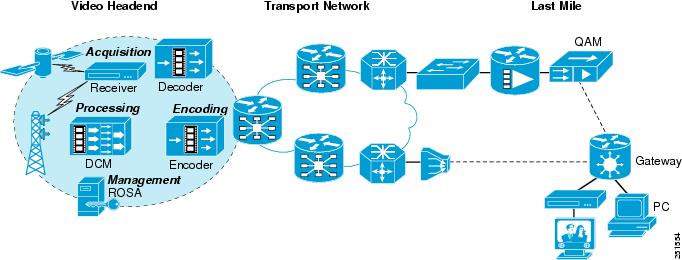
Figure 1-2 shows a Cisco VAMS topology in a video headend environment, and Figure 1-3 shows an example topology in the video transport network.
Cisco VAMS 2.0 in a Video Headend Environment
Figure 1-2 shows a Cisco VAMS topology in a video headend environment.
Figure 1-2 Cisco Video Assurance Management Solution 2.0 Components for Video Headend Monitoring
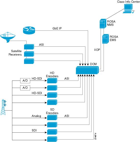
The devices in the video headend perform the following functions.
•![]() Digital Program Acquisition—The securing of content from satellite or terrestrial sources and preparation of the content for digital delivery. The acquisition process uses satellite receivers, off-air receivers, and integrated receiver/decoder (IRD) solutions to convert RF streams to digital format including serial digital interface (SDI) and asynchronous serial interface (ASI).
Digital Program Acquisition—The securing of content from satellite or terrestrial sources and preparation of the content for digital delivery. The acquisition process uses satellite receivers, off-air receivers, and integrated receiver/decoder (IRD) solutions to convert RF streams to digital format including serial digital interface (SDI) and asynchronous serial interface (ASI).
•![]() Digital Program Storage—The storage and insertion of additional, non-live broadcast programming like video-on-demand or advertising.
Digital Program Storage—The storage and insertion of additional, non-live broadcast programming like video-on-demand or advertising.
•![]() Digital Program Distribution—Includes program preparation and aggregation, modulation, encapsulation and other technical processes to prepare programming for delivery.
Digital Program Distribution—Includes program preparation and aggregation, modulation, encapsulation and other technical processes to prepare programming for delivery.
•![]() Digital Program Delivery—Transport to the receiver devices and set top boxes, which allows subscribers a high quality view of video programming.
Digital Program Delivery—Transport to the receiver devices and set top boxes, which allows subscribers a high quality view of video programming.
The hardware devices in the headend include:
•![]() Video Encoders—Video Encoders are used to compress the video into a standard compression technology such as MPEG-2. Digitalization and compression allow for bandwidth saving over the available frequency and enable the delivery of video over low bandwidth environments.
Video Encoders—Video Encoders are used to compress the video into a standard compression technology such as MPEG-2. Digitalization and compression allow for bandwidth saving over the available frequency and enable the delivery of video over low bandwidth environments.
•![]() Video Rate Shaping (Transrating) and Video Encapsulation Devices—The video content is typically received at the video headend facility through satellite receivers, off-air, or through a terrestrial route. Since the video streams are typically bundled together as a multiplex from the satellite, they first need to be de-multiplexed and converted to separate video streams. In addition, since these video streams are usually in a variable bit rate (VBR) format, they might need to be rate reduced and rate shaped to get a constant bit rate (CBR). The job of the video rate shaping, also known as transrating, is to convert the video to a constant bit rate while also reducing the video bit rate.
Video Rate Shaping (Transrating) and Video Encapsulation Devices—The video content is typically received at the video headend facility through satellite receivers, off-air, or through a terrestrial route. Since the video streams are typically bundled together as a multiplex from the satellite, they first need to be de-multiplexed and converted to separate video streams. In addition, since these video streams are usually in a variable bit rate (VBR) format, they might need to be rate reduced and rate shaped to get a constant bit rate (CBR). The job of the video rate shaping, also known as transrating, is to convert the video to a constant bit rate while also reducing the video bit rate.
Video encapsulation is another key component of headend functionality. Encapsulation is important because, although service providers receive video from different sources and in multiple formats, they need to be able to deliver it over their networks as efficiently and cost-effectively as possible. Many providers continue to build out fiber networks; so, while they may want to deliver MPEG-over-ATM today, they are likely to have a migration plan to GbE for the fiber-fed portions of their networks. Some independent telephone companies also have a cable plant in their network, and want to use their headend to upgrade cable customers to digital cable TV, and also deliver video signals through ADSL over their ATM network with the same equipment.
•![]() Digital Content Manager (DCM)—The DCM is a critical component of the Video headend topology. The DCM provides these features:
Digital Content Manager (DCM)—The DCM is a critical component of the Video headend topology. The DCM provides these features:
–![]() Multiplexing/re-multiplexing
Multiplexing/re-multiplexing
–![]() Transrating, grooming, and rate clamping
Transrating, grooming, and rate clamping
–![]() Statistical multiplexing
Statistical multiplexing
–![]() Digital program insertion
Digital program insertion
–![]() Transport service protection
Transport service protection
–![]() Bandwidth analysis
Bandwidth analysis
–![]() Asynchronous serial interface/Internet protocol conversion
Asynchronous serial interface/Internet protocol conversion
The DCM can export alerts related to these features into the ROSA Management system for video service correlation and association with other events solicited from the IP transport.
In the Cisco VAMS 2.0 environment, the DCM sends events directly to the ROSA NMS, through the Internet Inter-ORB Protocol (IIOP), or indirectly, through the ROSA EMS. The ROSA NMS is configured to relay the events to Cisco Info Center. Cisco Info Center correlates the events from the video headend with events that it receives from the components of the video transport network.
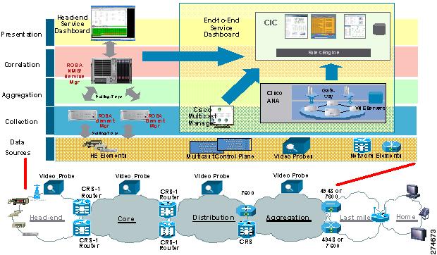
Cisco VAMS in a Video Transport Network
Figure 1-3 shows Cisco VAMS 2.0 in a video transport network.
Figure 1-3 Cisco Video Assurance Management Solution 2.0 Components for Video Transport Monitoring
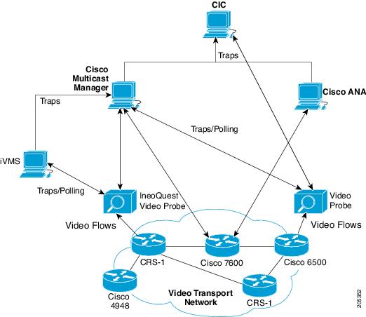
Cisco VAMS 2.0 monitors the network elements (NEs) in the video transport network by using Cisco ANA, and monitors video flows by using video probes. Cisco ANA sends network topology information and other events to Cisco Info Center. The video probes monitor video flows in the video transport network and send events either directly to Cisco Info Center, or send events to Cisco Multicast Manager, which then forwards the events to Cisco Info Center.
Cisco Info Center correlates the events that it receives from ANA, the video probes, and Cisco Multicast Manager and generates events that provide more detailed information about the video service. For additional information on Cisco Info Center in the VAMS 2.0 environment, see Cisco Info Center.
Cisco VAMS 2.0 in a Wireline Network
Figure 1-4 shows the Cisco VAMS 2.0 in a wireline network.
Figure 1-4 Cisco Video Assurance Management Solution 2.0 in a Wireline Network
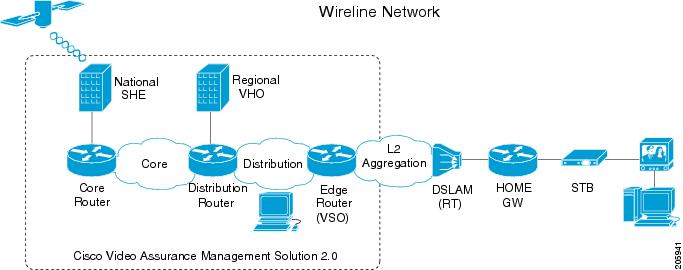
Cisco VAMS 2.0 covers the video transport network and focuses on the core and distribution networks shown in Figure 1-4. See also Figure 1-3 for an example of the Cisco devices Cisco VAMS 2.0 manages. See Figure 1-2 for an example of the headend devices Cisco VAMS 2.0 manages.
For detailed information about this supported architecture, see the Cisco Wireline Video/IPTV Solution Design and Implementation Guide, Release 1.1, viewable online at:
More information about Cisco Internet Protocol Television (IPTV) solutions for wireline carriers is viewable online at:
http://www.cisco.com/en/US/netsol/ns610/networking_solutions_solution_category.html
Cisco VAMS 2.0 in a Cable Network
Figure 1-5 shows the Cisco VAMS 2.0 in a cable network.
Figure 1-5 Cisco Video Assurance Management Solution 2.0 in a Cable Network
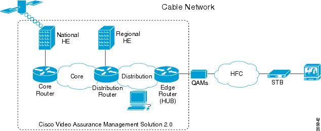
Cisco VAMS 2.0 covers the video transport network and focuses on the core and distribution networks shown in Figure 1-5. See also Figure 1-3 for an example of the Cisco devices the Cisco VAMS 2.0 manages.
For detailed information about this supported architecture, see the Cisco Gigabit-Ethernet Optimized Video Networking Solution for Cable Design and Implementation Guide, Release 3.0, viewable online at:
More information about Cisco cable video solutions is viewable online at:
http://www.cisco.com/en/US/netsol/ns457/networking_solutions_solution_category.html
Cisco VAMS Solution Components
The Cisco VAMS 2.0 solution includes the following components:
•![]() Cisco Multicast Manager 2.5.4
Cisco Multicast Manager 2.5.4
Figure 1-6 shows the components in the VAMS 2.0 architecture.
Figure 1-6 VAMS 2.0 System Architecture
Network Elements in the Video Transport Network
Cisco VAMS 2.0 monitors these network elements (NEs), which form the core of the video transport network (see Figure 1-3):
•![]() Cisco 7600 Series router—A carrier-class edge router that offers integrated, high-density Ethernet switching, carrier-class Internet Protocol/Multiprotocol Label Switching (IP/MPLS) routing, and 10-Gb/s interfaces.
Cisco 7600 Series router—A carrier-class edge router that offers integrated, high-density Ethernet switching, carrier-class Internet Protocol/Multiprotocol Label Switching (IP/MPLS) routing, and 10-Gb/s interfaces.
•![]() Cisco Catalyst 6500 Series switch—As the premier intelligent, multilayer modular Cisco switch, the Catalyst 6500 Series delivers secure, converged, end-to-end services, from the wiring closet to the core network, the data center, and the WAN edge.
Cisco Catalyst 6500 Series switch—As the premier intelligent, multilayer modular Cisco switch, the Catalyst 6500 Series delivers secure, converged, end-to-end services, from the wiring closet to the core network, the data center, and the WAN edge.
•![]() CRS-1—A carrier routing system that service providers use to deliver data, voice, and video services over a highly available and scalable IP network.
CRS-1—A carrier routing system that service providers use to deliver data, voice, and video services over a highly available and scalable IP network.
•![]() Cisco Catalyst 4948 Series switch—A low-latency, Layer 2-4, switch that offers performance and reliability for low-density, multi-layer aggregation of high-performance servers and workstations.
Cisco Catalyst 4948 Series switch—A low-latency, Layer 2-4, switch that offers performance and reliability for low-density, multi-layer aggregation of high-performance servers and workstations.
•![]() Cisco 12000 Series routers—A portfolio of intelligent routing solutions that scale from 2.5- to n x10 Gbps capacity per slot, enabling carrier-class IP/Multiprotocol Label Switching (MPLS) networks and accelerating the evolution to IP Next-Generation Networks.
Cisco 12000 Series routers—A portfolio of intelligent routing solutions that scale from 2.5- to n x10 Gbps capacity per slot, enabling carrier-class IP/Multiprotocol Label Switching (MPLS) networks and accelerating the evolution to IP Next-Generation Networks.
•![]() Video Headend Equipment—Video headend equipment includes satellite receivers, off-air receivers, integrated receiver/decoder (IRD) solutions, HD encoders, SD encoders, and the DCM.
Video Headend Equipment—Video headend equipment includes satellite receivers, off-air receivers, integrated receiver/decoder (IRD) solutions, HD encoders, SD encoders, and the DCM.

Note ![]() You must equip these NEs with IOS software that enables the NEs to monitor multicast video flows in the network. See the "Solution Component Versions" section, for a list of the required IOS software.
You must equip these NEs with IOS software that enables the NEs to monitor multicast video flows in the network. See the "Solution Component Versions" section, for a list of the required IOS software.
Solution Component Versions
Besides the Cisco VAMS 2.0 software package, the Cisco VAMS 2.0 solution supports these components and software version levels:
|
|
|
|---|---|
Active Network Abstraction (ANA)1 |
3.6 Service Pack 3 (3.6.3) |
Cisco Multicast Manager |
2.5.4 |
ROSA Element Management System |
3.03.10 The ROSA EMS is supported on the following operating systems: • • • • |
ROSA Copernicus NMS |
3.0.63 |
Digital Content Manager (DCM) |
Model D9900 and D9901 with GbE interface card. DCM software V06.05.02. |
Cisco 7600 Series router (7600-SUP720-3BXL with redundant SUP720-3BXL) Line cards: WS-X6704-10GE, WS-X6708-10GE, WS-X6748-SFP, WS-X6748-GE-TX, WS-X6724-SFP, RSP720-3CXL, 7600-ES20-10G3CXL, 7600-SIP-400, 7600-SIP-600, SPA-1XTENGE-XFP, SPA-2X1GE, and optional WS-F6700-DFC3BXL |
12.2(33)SRB2, 12.2(33)SRB3, 12.2(33)SRD1 |
Cisco Catalyst 6500 Series switch |
12.2(33)SXI |
Cisco 12000 series routers |
IOS XR 3.7.1 |
Cisco CRS-1 Line cards: CRS-MSC, CRS1-SIP-800 (with SPA-8X1GE), 8-10GE |
IOS-XR 3.7.1 |
Cisco Catalyst 4948 Series switch (CAT4948-10GE) |
12.2(25)EWA6 or 12.2(31)SGA1 |
Cisco Info Center (includes IBM Tivoli Netcool products)2 |
Cisco Info Center, which includes • • • • |
iVMS |
3.0, patch 24 |
Bridge Technologies video probe |
VB Series: Version: 3.1.0-26 |
IneoQuest video probe |
• • • • |
Mixed Signals video probe |
Sentry 136 Digital Content Monitor3 |
PixelMetrix video probe |
DVStation: Version: 4.17.0 |
Tektronix video probe |
MTM400 |
1 You must purchase base VNEs before installing the VNE extensions. For example, you must acquire the Cisco 7600 series router group VNE license to use the Cisco 7600 VNE extensions. 2 Cisco Info Center is an OEM product that includes the IBM Tivoli Netcool Suite. 3 Cisco VAMS 2.0 does not support carousel-related traps for the Mixed Signals Sentry 136. |
Cisco Multicast Manager 2.5.4
This section describes the hardware and software components of CMM 2.5.4.
Cisco Multicast Manager 2.5.4 Hardware Components
CMM 2.5.4 hardware comprises:
x86 Server
The CMM 2.5.4 x86 server uses one of these processors in a x86-type computer:
•![]() Dual AMD Opteron 250.
Dual AMD Opteron 250.
•![]() 2.4 GHz 64-bit (recommended for a large enterprise network of more than 500 devices).
2.4 GHz 64-bit (recommended for a large enterprise network of more than 500 devices).
•![]() 2.8 GHz Intel Pentium IV.
2.8 GHz Intel Pentium IV.
•![]() 2.8 GHz Intel Xeon processor.
2.8 GHz Intel Xeon processor.
•![]() Dual 2.8 GHz Intel Pentium IV.
Dual 2.8 GHz Intel Pentium IV.
•![]() Dual 2.8 GHz Intel Xeon processor (recommended for a large enterprise network of more than 500 devices).
Dual 2.8 GHz Intel Xeon processor (recommended for a large enterprise network of more than 500 devices).
Sun Microsystems Server
The CMM 2.5.4 Sun Microsystems server uses one of these Sun Fire series workstations:
•![]() Sun Fire V440 (up to four 1.593 GHz UltraSPARC IIIi processors for a large enterprise network of more than 500 devices),
Sun Fire V440 (up to four 1.593 GHz UltraSPARC IIIi processors for a large enterprise network of more than 500 devices),
•![]() Sun Fire V240 (one 1.34 GHz or two 1.5 GHz UltraSPARC processors).
Sun Fire V240 (one 1.34 GHz or two 1.5 GHz UltraSPARC processors).
CMM 2.5.4 Application
Using an x86-type computer running Linux or a Sun Microsystems Sun Fire series workstation running Solaris, the CMM 2.5.4 application (a web-based multicast troubleshooting tool) has two components: Administration and Multicast Manager.
CMM 2.5.4 uses SNMP MIB polling to monitor devices and traffic in the network. CMM 2.5.4 also provides metrics and alerts, which it then forwards to Cisco Info Center as SNMP traps. Based on the unique requirements of the network environment, the SNMP traps are user-configurable.
CMM 2.5.4 can monitor multicast-specific data such as:
•![]() Rendezvous points (RP)
Rendezvous points (RP)
•![]() Designated routers (DR)
Designated routers (DR)
•![]() Multicast traffic (Layer 2 and Layer 3)
Multicast traffic (Layer 2 and Layer 3)
•![]() Multicast bandwidth (Layer 2 and Layer 3)
Multicast bandwidth (Layer 2 and Layer 3)
•![]() Layer 3 multicast trees
Layer 3 multicast trees
•![]() Tree Change events
Tree Change events
•![]() PPS/BPS per flow monitoring
PPS/BPS per flow monitoring
CMM 2.5.4 also provides detailed diagnostics and a health-check capability.
You use CMM 2.5.4 to set thresholds, generate notifications, and forward them to Cisco Info Center.
See the User Guide for Cisco Multicast Manager 2.5, viewable online at:
Cisco Multicast Manager 2.5.4 System Requirements
Table 1-2 lists the hardware and software requirements for the CMM 2.5.4.
Cisco Multicast Manager 2.5.4 Software Components
As described previously, the CMM 2.5.4 application has an Administration and a Multicast Manager tool. You can select either tool from the menu at the upper left of CMM Web interface. You can perform the following tasks with each tool:
Administration
The Administration tool allows you to:
•![]() Manage domains
Manage domains
•![]() Use administrative utilities
Use administrative utilities
•![]() Configure security
Configure security
•![]() Manage users
Manage users
•![]() Perform discovery
Perform discovery
•![]() Configure devices
Configure devices
•![]() Configure global polling
Configure global polling
•![]() Configure multicast polling
Configure multicast polling
•![]() Manage addresses
Manage addresses
Multicast Manager
The Multicast Manager tool allows you to:
•![]() View events through the Home page.
View events through the Home page.
•![]() View topology through the Topology page, such as:
View topology through the Topology page, such as:
–![]() Each router and its local interfaces.
Each router and its local interfaces.
–![]() The interfaces on each of the router's Protocol Independent Multicast (PIM) neighbors.
The interfaces on each of the router's Protocol Independent Multicast (PIM) neighbors.
–![]() The names of the routers and their PIM neighbors.
The names of the routers and their PIM neighbors.
•![]() Manage report through the Reporting page, such as:
Manage report through the Reporting page, such as:
–![]() A record of the latest SNMP traps sent.
A record of the latest SNMP traps sent.
–![]() Historical graphs or trends.
Historical graphs or trends.
–![]() Routers in the database IOS versions.
Routers in the database IOS versions.
–![]() Video probe reports.
Video probe reports.
–![]() Reports on VPN routing/forwarding instances (VRFs).
Reports on VPN routing/forwarding instances (VRFs).
•![]() Manage a global view and a router-specific view of your network through the Diagnostics page, by:
Manage a global view and a router-specific view of your network through the Diagnostics page, by:
–![]() Showing active sources and groups in the network.
Showing active sources and groups in the network.
–![]() Finding sources and receivers in the network.
Finding sources and receivers in the network.
–![]() Viewing the status of all devices in the current multicast domain.
Viewing the status of all devices in the current multicast domain.
–![]() Viewing all the routers in the database.
Viewing all the routers in the database.
–![]() Viewing all the RPs that CMM is aware of, based on discovery.
Viewing all the RPs that CMM is aware of, based on discovery.
–![]() Seeing the interfaces that have joined a particular group.
Seeing the interfaces that have joined a particular group.
–![]() Viewing all the routers running Multicast Source Discovery Protocol (MSDP) and their peering connectivity. You can also view details for a specific router, such as peering information and the SA cache.
Viewing all the routers running Multicast Source Discovery Protocol (MSDP) and their peering connectivity. You can also view details for a specific router, such as peering information and the SA cache.
–![]() Viewing Layer 2 Multicast Information and Layer 2 Host IPs.
Viewing Layer 2 Multicast Information and Layer 2 Host IPs.
–![]() Running preconfigured network tests using the Health Check facility.
Running preconfigured network tests using the Health Check facility.
–![]() Enable the CMM to gather accurate packet forwarding statistics and other information in a timely manner.
Enable the CMM to gather accurate packet forwarding statistics and other information in a timely manner.
–![]() Viewing the top 20 talkers, sorted by long term.
Viewing the top 20 talkers, sorted by long term.
–![]() Viewing diagnostic information about video probes and the flows that they are monitoring.
Viewing diagnostic information about video probes and the flows that they are monitoring.
–![]() Viewing a detailed trace about a video flow and a topology tree that shows: RPs, routers, interfaces, and probes.
Viewing a detailed trace about a video flow and a topology tree that shows: RPs, routers, interfaces, and probes.
–![]() Viewing detailed information about the status of Multicast VPNs, including: VRF table configurations, Provider Edge (PE) device configurations, and the current status of a specified VRF.
Viewing detailed information about the status of Multicast VPNs, including: VRF table configurations, Provider Edge (PE) device configurations, and the current status of a specified VRF.
–![]() Viewing specific multicast diagnostics on a router.
Viewing specific multicast diagnostics on a router.
In addition, you can view a PDF version of the User Guide for the Cisco Multicast Manager 2.5 through the Help page.
For complete hardware and software requirements, see the following books:
Installation Guide for the Cisco Multicast Manager 2.5, viewable online at: http://www.cisco.com/en/US/docs/net_mgmt/cisco_multicast_manager/2.5/installation/guide/
CMM_25_install_guide.html
User Guide for the Cisco Multicast Manager 2.5, viewable online at:
ROSA NMS
The ROSA Copernicus NMS provides monitoring for the DCM and video headend equipment. The ROSA NMS runs on a dedicated hardware device. The ROSA software runs on a client device that you use to access the Copernicus server.
For information on the Copernicus ROSA Network Management Server device, see the data sheet for the ROSA Copernicus NMS at the following location:
ROSA NMS Client Requirements
The computer used to run the ROSA NMS client must meet these requirements:
ROSA NMS Architecture and Process Flow
Figure 1-7 shows the ROSA NMS architecture.
Figure 1-7 ROSA NMS Process Flow
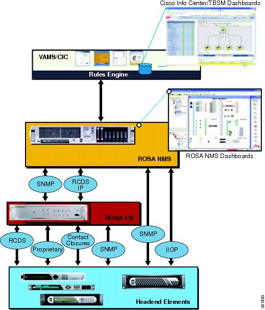
In the VAMS 2.0 architecture, the process flow of alerts is as follows:
1. ![]() Data source elements such as the SD and HD encoders and the DCM report events either through the ROSA EMS or directly to the ROSA Copernicus NMS. The events are reported as SNMP traps or as Resource Cataloging and Distribution System (RCDS) IP messages.
Data source elements such as the SD and HD encoders and the DCM report events either through the ROSA EMS or directly to the ROSA Copernicus NMS. The events are reported as SNMP traps or as Resource Cataloging and Distribution System (RCDS) IP messages.
2. ![]() The ROSA client dashboard allows alerts that are collected from headend devices to be mapped against the reporting hardware and the affected video services.
The ROSA client dashboard allows alerts that are collected from headend devices to be mapped against the reporting hardware and the affected video services.
3. ![]() The ROSA NMS uses an SNMP-based northbound interface to send alerts to Cisco Info Center.
The ROSA NMS uses an SNMP-based northbound interface to send alerts to Cisco Info Center.
Event Categories Reported to Cisco Info Center
The ROSA NMS reports these categories of events to Cisco Info Center:
•![]() Service Alerts
Service Alerts
•![]() ETR-290 First Priority Alarms
ETR-290 First Priority Alarms
•![]() Video Transport Events
Video Transport Events
•![]() Additional Video Quality Measurements
Additional Video Quality Measurements
Service Alerts
The ROSA NMS is responsible for monitoring and detecting all categories of service backup events that can occur in the video headend.
When a redundancy scheme is applied to a DCM, the terminology used depends on where the protection is applied. When backup services are applied on the input side of DCM this is called TS backup. On output, the term Service backup is used.
Upon a service backup cutover, ROSA detects and associates the event with both the hardware and defined video service in the ROSA NMS dashboard. The event is then sent northbound using the CopMsgNew structure defined in the ROSA NMS MIB.
Cisco Info Center rules for VAMS 2.0 process the specific alerts from ROSA and the other VAMS components such as CMM, ANA, and video probes. These alerts are associated through a common multicast association for representation at the VAMS 2.0 Cisco Info Center dashboard.
Service alerts include:
•![]() Service Loss—For each incoming service, one or more alarms can be defined to trigger a Service Loss alarm. A Transport Stream Loss alarm is triggered when a Service Loss alarm occurs.
Service Loss—For each incoming service, one or more alarms can be defined to trigger a Service Loss alarm. A Transport Stream Loss alarm is triggered when a Service Loss alarm occurs.
Triggers for a service loss alarm include TS Sync Loss, UDP Stream Loss, Missing in PAT, PMT Error, and PID Error. For a description of these triggers, see ETR-290 First Priority Alarms.
•![]() Service in Backup (Service Loss)—This alarm is generated when a service is in backup state triggered by a Service Loss alarm.
Service in Backup (Service Loss)—This alarm is generated when a service is in backup state triggered by a Service Loss alarm.
•![]() Service Loss at Output—This alarm is generated for an outgoing service for which the corresponding incoming service and incoming backup services are in Service Loss state.
Service Loss at Output—This alarm is generated for an outgoing service for which the corresponding incoming service and incoming backup services are in Service Loss state.
•![]() Service in Backup (TS Loss)—This alarm is generated when a service is in backup state triggered by a TS Loss alarm.
Service in Backup (TS Loss)—This alarm is generated when a service is in backup state triggered by a TS Loss alarm.
ETR-290 First Priority Alarms
European Telecommunications Standards Institute 290 (ETR-290) First Priority alarms are defined in the ETR-290 specification. ETR-290 First Priority alarms include:
•![]() TS Loss—The first byte of a Transport Stream packet header is the synchronization byte (0x47). A TS Loss error occurs when the synchronization byte in a sequence of at least two Transport Stream packets are not detected.
TS Loss—The first byte of a Transport Stream packet header is the synchronization byte (0x47). A TS Loss error occurs when the synchronization byte in a sequence of at least two Transport Stream packets are not detected.
•![]() CC Error—Indicates a discontinuity error in the MPEG TS structure for a particular video program.
CC Error—Indicates a discontinuity error in the MPEG TS structure for a particular video program.
•![]() Sync Byte Error—The synchronization byte in a Transport Stream packet is not detected. A Transport Stream Loss alarm is also triggered.
Sync Byte Error—The synchronization byte in a Transport Stream packet is not detected. A Transport Stream Loss alarm is also triggered.
•![]() PAT Error—Occurs when the PMT reference in the Program Association Table (PAT) for the service is missing. A Service Loss alarm is also triggered.
PAT Error—Occurs when the PMT reference in the Program Association Table (PAT) for the service is missing. A Service Loss alarm is also triggered.
•![]() PMT Error—Occurs when the Program Map Table (PM) for the service is not available within a particular time interval or contains errors. A Service Loss alarm is also triggered.
PMT Error—Occurs when the Program Map Table (PM) for the service is not available within a particular time interval or contains errors. A Service Loss alarm is also triggered.
•![]() PID Error—A Packet ID (PID) error occurs when components with PMT reference are not found within a particular time interval. A Service Loss alarm is also triggered.
PID Error—A Packet ID (PID) error occurs when components with PMT reference are not found within a particular time interval. A Service Loss alarm is also triggered.
Video Transport Events
The ROSA NMS generates the following video transport events:
•![]() UDP Stream Loss—A Service Loss alarm is triggered when the port of the incoming Transport Stream to which the service belongs no longer detects packets at the corresponding UDP port.
UDP Stream Loss—A Service Loss alarm is triggered when the port of the incoming Transport Stream to which the service belongs no longer detects packets at the corresponding UDP port.
•![]() Bandwidth Exceeded—The sum of the services and components within a Transport Stream has exceeded the bit rate that is assigned to the Transport Stream.
Bandwidth Exceeded—The sum of the services and components within a Transport Stream has exceeded the bit rate that is assigned to the Transport Stream.
•![]() Destination IP Unresolved—This alarm is generated when the MAC address for a unicast IP address of an outgoing Transport Stream cannot be resolved.
Destination IP Unresolved—This alarm is generated when the MAC address for a unicast IP address of an outgoing Transport Stream cannot be resolved.
Additional Video Quality Measurements
The ROSA NMS generates several additional events that measure video quality. These events include:
•![]() Unreferenced PID Error—The Transport Stream is permitted to contain only packets with program-specific information (PSI and SI tables), packets with certain PIDs that are reserved in the MPEG-2 standard, and packets that are identified in a Program Map Table (PMT).
Unreferenced PID Error—The Transport Stream is permitted to contain only packets with program-specific information (PSI and SI tables), packets with certain PIDs that are reserved in the MPEG-2 standard, and packets that are identified in a Program Map Table (PMT).
•![]() PMT Section Exceeds 1K—The PMT section is limited to 1 KB. This alarm occurs if the PMT section exceeds this limit.
PMT Section Exceeds 1K—The PMT section is limited to 1 KB. This alarm occurs if the PMT section exceeds this limit.
•![]() Missing Forward Error Correction (FEC) Stream—This alarm is generated if one or both FEC streams are missing for the incoming Transport Stream.
Missing Forward Error Correction (FEC) Stream—This alarm is generated if one or both FEC streams are missing for the incoming Transport Stream.
•![]() Payload Bit Rate Too Low—This alarm is generated when the bit rate of the payload of an outgoing Transport Stream drops below a configurable threshold.
Payload Bit Rate Too Low—This alarm is generated when the bit rate of the payload of an outgoing Transport Stream drops below a configurable threshold.
•![]() No FEC Licensing Available (Decoding)—This alarm is generated if no license is available at the arrival of an incoming Transport Stream when the Default Input FEC Settings Mode is set to 1D FEC or 2D FEC. In this case FEC for the corresponding Transport Stream is disabled.
No FEC Licensing Available (Decoding)—This alarm is generated if no license is available at the arrival of an incoming Transport Stream when the Default Input FEC Settings Mode is set to 1D FEC or 2D FEC. In this case FEC for the corresponding Transport Stream is disabled.
•![]() No FEC Licensing Available (Encoding)—This alarm is generated when not enough licenses are available after a reboot if the Default Input FEC Settings Mode is set to 1D FEC or 2D FEC.
No FEC Licensing Available (Encoding)—This alarm is generated when not enough licenses are available after a reboot if the Default Input FEC Settings Mode is set to 1D FEC or 2D FEC.
•![]() FEC L/D Error—This alarm is generated when a Transport Stream enters the device with forward error correction (FEC) scheme L x D > 100.
FEC L/D Error—This alarm is generated when a Transport Stream enters the device with forward error correction (FEC) scheme L x D > 100.
•![]() Stuffing Rate Too Low—This alarm is generated when the bit rate of the stuffing within an outgoing Transport Stream drops below a configurable threshold.
Stuffing Rate Too Low—This alarm is generated when the bit rate of the stuffing within an outgoing Transport Stream drops below a configurable threshold.
•![]() Bit Rate Too Variable for CBR Dejittering—This alarm is generated when the bit rate for a transport stream is too variable for constant bit-rate dejittering to be used.
Bit Rate Too Variable for CBR Dejittering—This alarm is generated when the bit rate for a transport stream is too variable for constant bit-rate dejittering to be used.
ROSA NMS Service Backup Procedures
The DCM and the ROSA NMS allow you to configure service backup protection for video headend devices. The main categories of service backup protection in the DCM included in the VAMS 2.0 architecture are:
•![]() Gigabit Ethernet Port Protection
Gigabit Ethernet Port Protection
•![]() ETR-290 Priority 1 Ingress Monitoring
ETR-290 Priority 1 Ingress Monitoring
Service Backup Protection
The ROSA NMS is responsible for monitoring and detecting all categories of service backup events that can occur in the video headend. Upon a service backup cutover, ROSA detects the event and associates it with both the hardware and the video service that is defined in the ROSA NMS dashboard. The event is then sent northbound using the CopMsgNew structure defined in the ROSA NMS MIB.
Cisco Info Center rules for VAMS 2.0 process specific alerts from ROSA and the other VAMS components, such as CMM, ANA, and video probes. These alerts are combined into a Cisco Info Center alert based on a common multicast association for representation at the Tivoli Business Service Manager (TBSM) dashboard.
Service Loss Notification
Network operators can configure parameters that specify the thresholds applied to video services during acquisition. In the DCM, backup streams can be chosen to replace the primary stream. TS backup results in a single output stream sourced from one of many input streams.
Output service loss is a critical event resulting in complete service disruption from the video headend. ROSA detects this event and associates it with the affected hardware and video service in the ROSA NMS dashboard. The event is also detected in the video transport by other VAMS components as multicast flow loss and potentially multicast state change. Events are summarized at the Cisco Info Center Dashboard based on common multicast information and associated with the affected video service.
Many events can trigger a service loss event, including:
•![]() TSSL (ASI).
TSSL (ASI).
•![]() UDP Loss (GbE.)
UDP Loss (GbE.)
•![]() First Priority Alarms, for example, missing information in the PAT, PMT, or PID.
First Priority Alarms, for example, missing information in the PAT, PMT, or PID.
All trigger thresholds are configurable (per I/O stream). A template can be configured on a per I/O board basis. A service loss configuration table can be configured in the DCM based on input transport stream (TS) settings.
Chassis Protection
Chassis protection includes:
•![]() ROSA NMS (Copernicus) Protection
ROSA NMS (Copernicus) Protection
•![]() ROSA EM Protection
ROSA EM Protection
•![]() Standalone or Heartbeat Loss Monitoring
Standalone or Heartbeat Loss Monitoring
Gigabit Ethernet Port Protection
Gigabit Ethernet (GbE) port protection consists of (Main/backup), failover based on:
•![]() Link/UDP traffic loss
Link/UDP traffic loss
•![]() ASI port / TS protection
ASI port / TS protection
•![]() TS (ASI / IP) protection—Any TS can protect any other TS.
TS (ASI / IP) protection—Any TS can protect any other TS.
ETR-290 Priority 1 Ingress Monitoring
ETR-290 Priority 1 Ingress Monitoring provides individual service protection by using ETR-290 Priority 1 alarms as triggers. For a list of the ETR-290 Priority 1 alarms, see ETR-290 First Priority Alarms.
Cisco Info Center
Cisco Info Center delivers real-time centralized monitoring and root-cause analysis by integrating the IBM Tivoli/ Netcool components and with Cisco ANA 3.6.3, CMM 2.5.4, and video probe devices.
Cisco Info Center alone provides real-time monitoring, management, and event deduplication3 or pruning, and helps enterprises and service providers proactively manage their IT infrastructures to ensure the continuous uptime of business services and applications.
The Cisco Info Center/Netcool components comprise:
•![]() IBM Tivoli Netcool/OMNIbus and ObjectServer
IBM Tivoli Netcool/OMNIbus and ObjectServer
•![]() IBM Tivoli Business Service Manager
IBM Tivoli Business Service Manager
•![]() IBM Tivoli Netcool GUI Foundation
IBM Tivoli Netcool GUI Foundation
IBM Tivoli Netcool/OMNIbus and ObjectServer
The IBM Tivoli Netcool/OMNIbus service level management (SLM) system collects enterprise-wide event information from several different network data sources, and presents a simplified view of this information to operators and administrators.
This information:
•![]() Assigns information to operators.
Assigns information to operators.
•![]() Travels to help desk systems.
Travels to help desk systems.
•![]() Is logged in a database.
Is logged in a database.
•![]() Replicates on a remote Netcool/OMNIbus system.
Replicates on a remote Netcool/OMNIbus system.
•![]() Triggers automatic responses to certain alerts.
Triggers automatic responses to certain alerts.
Netcool/OMNIbus can also consolidate information from different domain-limited network management platforms in remote locations. By working in conjunction with existing management systems and applications, Netcool/OMNIbus minimizes deployment time; thus, network operators save time in managing the network.
Netcool/OMNIbus tracks alert information in a high-performance, in-memory database, and presents information of interest to you through individually configurable filters and views.
Netcool/OMNIbus automation functions can perform intelligent processing on managed alerts.
The ObjectServer is the in-memory database server at the core of Netcool/OMNIbus. The ObjectServer forwards alert information from external programs, such as probes, monitors, and gateways, stored and managed in database tables, and is visible in the event list.
For a detailed listing of the Netcool/Omnibus documents, see the Cisco Info Center 7.1 Documentation Guide and Supplemental License Agreement and the Cisco Info Center 7.2 Documentation Guide and Supplemental License Agreement. These documents are viewable online at:
http://www.cisco.com/en/US/products/sw/netmgtsw/ps996/
products_documentation_roadmaps_list.html
IBM Tivoli Netcool/OMNIbus and ObjectServer Requirements
For detailed information on operating system requirements, JRE support, and user interface support for IBM Tivoli Netcool/OMNIbus, see the Netcool/OMNIbus 7.2 Installation and Deployment Guide, available online at:
IBM Tivoli Netcool/Webtop
IBM Tivoli Netcool/Webtop publishes alerts for viewing in a web browser. Users can manipulate them by using an active event list launched from a web browser. The Webtop includes server administration pages to set up users, table views, and other configurable elements.
Webtop includes the Webtop Editor; a tool for creating and editing maps (filters and views). Webtop publishes Netcool alerts and active event list applets over HTTP or HTTPS4 (HTTP with SSL) protocol to supported web browsers. Launched from a web browser, the active event list offers the functionality of Netcool/Java EventList (JEL) to acknowledge, prioritize, and delete alerts by using the Webtop technology.
Using a client-server architecture, the Webtop server runs inside the IBM Tivoli Netcool GUI Foundation application (see the "IBM Tivoli Netcool GUI Foundation" section for more information). Clients connect to the IBM Tivoli Netcool GUI Foundation to access Netcool/Webtop.
See the administration guide for this product, available on the IBM website.
You can also launch Netcool/Webtop from the Tivoli Business Service Manager (TBSM) application. For information on launching TBSM and Netcool/Webtop to view VAMS 2.0 alerts, see Monitoring ANA, CMM, and Video Probe Events with TBSM, page 6-3.
IBM Tivoli Netcool/Webtop Requirements
For detailed information on operating system requirements and other requirements for IBM Tivoli Netcool/Webtop, see the Netcool Webtop 2.0 Administration Guide, available online at:
Ensure that the IBM Tivoli Netcool Security Manager is installed, running, and accessible; and that you know the host, port, and administrative username and password for the IBM Tivoli Netcool Security Manager before you install IBM Tivoli Netcool/Webtop. For information about how to install and configure the IBM Tivoli Netcool Security Manager, see the security manager installation guide for this product, available on the IBM website.
IBM Tivoli Netcool/Impact
IBM Tivoli Netcool/Impact is the analysis and correlation engine for the Netcool suite of network management products. IBM Tivoli Netcool/Impact allows you to extensively customize and enhance Netcool/OMNIbus and other Netcool products by adding such functionality as advanced event and business data correlation, event enrichment and event notification. In addition, you can use IBM Tivoli Netcool/Impact to integrate IBM Tivoli Netcool/OMNIbus with a wide variety of third-party software, including databases, messaging systems and network inventory applications.
IBM Tivoli Business Service Manager
IBM Tivoli Business Service Manager (TBSM) delivers technology to visualize and assure the health and performance of critical business services.
TBSM functions include:
•![]() Build business service models.
Build business service models.
•![]() Integrate business service status from data sources or event sources including the Netcool/OMNIbus ObjectServer.
Integrate business service status from data sources or event sources including the Netcool/OMNIbus ObjectServer.
•![]() Monitor service outages based on service level agreements.
Monitor service outages based on service level agreements.
•![]() Build customized business service views, scorecards, and dashboards.
Build customized business service views, scorecards, and dashboards.
•![]() Tailor views to different users and roles including service manager, operator, or executive.
Tailor views to different users and roles including service manager, operator, or executive.
•![]() Provide dynamic visualization of key performance indicators (KPIs) and other critical business metrics.
Provide dynamic visualization of key performance indicators (KPIs) and other critical business metrics.
•![]() Provide self-management through monitoring of key components by using IBM Tivoli Monitoring (ITM).
Provide self-management through monitoring of key components by using IBM Tivoli Monitoring (ITM).
The TBSM tools enable a service model that integrates with the Netcool/OMNIbus ObjectServer alerts, or optionally with the data from a structured query language (SQL) data source. TBSM processes the external data based on the service model data you create in the TBSM database and returns a new or updated TBSM service event to the Netcool/OMNIbus ObjectServer.
TBSM provides a console that allows you to logically link services and business requirements in the service model. The service model provides you with a view on the performance of your business services, second by second.
See the installation, quick start, administrator, service configuration, customizing, and troubleshooting guides for this product, available on the IBM website.
JRE Requirements
Netcool/TBSM version 4.1 requires the Java Runtime Environment (JRE) to be installed on your system.
Netcool/TBSM supports the following JREs:
•![]() Javasoft JRE 1.5 on Linux, Solaris, and Windows platforms
Javasoft JRE 1.5 on Linux, Solaris, and Windows platforms
•![]() IBM JRE 1.4.2 on AIX platforms
IBM JRE 1.4.2 on AIX platforms
•![]() HP JRE 1.5 on HP-UX platforms
HP JRE 1.5 on HP-UX platforms
Note ![]() JRE versions higher than 1.5 in client web browsers might result in a failure of the Service Viewer and the Service Details within the TBSM window.
JRE versions higher than 1.5 in client web browsers might result in a failure of the Service Viewer and the Service Details within the TBSM window.
IBM Tivoli Netcool GUI Foundation
The IBM Tivoli Netcool GUI Foundation (NGF) is a server application that delivers web-based Netcool products in a single, unified framework. The IBM Tivoli Netcool GUI Foundation provides single sign-on, consolidated user management, and a single point of access for different IBM Tivoli Netcool applications. The IBM Tivoli Netcool GUI Foundation also provides the ability to create customized pages and administer access to content by user, role, or group.
The IBM Tivoli Netcool GUI Foundation is installed automatically with the first IBM Tivoli Netcool GUI Foundation-enabled product. Subsequent products may install updated versions of the IBM Tivoli Netcool GUI Foundation. The Netcool GUI Foundation is not available separately.
The IBM Tivoli Netcool GUI Foundation uses IBM Tivoli Netcool/Security Manager for authentication and authorization.
See the administration guide for this product, available on the IBM website.
IBM Tivoli Netcool Probes
The IBM Tivoli Netcool Probes connect to an event source, detect and acquire event data, and forward the data to the ObjectServer as alerts. Probes use the logic specified in a rules file to manipulate the event elements before converting them into fields of an alert in the ObjectServer alerts.status table.
Uniquely designed, each probe can acquire event data from a specific source. Probes can also acquire data from any stable data source, including devices, databases, and log files.
The main probe used with Cisco VAMS 2.0 and Cisco Info Center is the MTTrapd (Multi-Threaded) probe, which monitors SNMP traps and events on both UDP and TCP sockets. Using rules defined in the custom rules files for Cisco VAMS 2.0, the MTTrapd probe parses events from the VAMS components and assembles them into enhanced messages that show detailed information about the event and the devices involved in the event.
Rules Files
Included in Cisco Info Center/Netcool, the rules files enable streamlined communication between the CMM, ROSA NMS, and Cisco ANA components and the Netcool ObjectServer. This functionality includes the decoding of CMM, ROSA NMS, and Cisco ANA trap information pushed up from CMM or Cisco ANA into the ObjectServer database on the Netcool server.
Cisco ANA 3.6.3
This section describes the hardware and software components of Cisco ANA 3.6.3.
Cisco ANA 3.6.3 Hardware Components
Cisco ANA 3.6.3 hardware comprises:
Note ![]() The hardware recommendations assume that the Cisco ANA 3.6.3 software will not share the hardware with additional applications.
The hardware recommendations assume that the Cisco ANA 3.6.3 software will not share the hardware with additional applications.
Cisco ANA Servers
Cisco ANA uses two server types, each performing different activities:
Cisco ANA Gateway
The Cisco ANA Gateway uses a Sun Fire V490 running Solaris OS 10. It is the gateway through which all clients, including any operations support systems or business support systems (OSS/BSS) applications as well as the Cisco ANA clients, can access the system. The gateway is an extended Cisco ANA unit (see the "Cisco ANA Unit" section). It enforces access control and security for all connections, and manages client sessions. In addition, it functions as a repository for storing configuration, network and system events, and alarms.
Another important function of the gateway is to map network resources to the business context. As a result, Cisco ANA can contain information not directly in the network (such as virtual private networks [VPNs] and subscribers) and display it to northbound applications.
Cisco ANA Gateway Requirements
Table 1-3 lists the hardware and software requirements for the Cisco ANA 3.6.3 gateway.
Note ![]() Do not use the Cisco ANA 3.6.3 servers (gateway and unit) with any application other than Cisco ANA 3.6.3.
Do not use the Cisco ANA 3.6.3 servers (gateway and unit) with any application other than Cisco ANA 3.6.3.
Cisco ANA Unit
The Cisco ANA unit uses a Sun Fire V490 running Solaris OS 10. This unit is a key element of the Cisco ANA system. Networked together, these units create a modular, scalable, and high-performance, distributed knowledge engine. Multiple units cover the entire network as a single complete entity for discovery, assurance, and activation.
Cisco ANA Unit Requirements
Table 1-4 lists the hardware and software requirements for the Cisco ANA 3.6.3 unit.
Note ![]() Do not use the Cisco ANA 3.6.3 servers (gateway and unit) with any application other than Cisco ANA 3.6.3.
Do not use the Cisco ANA 3.6.3 servers (gateway and unit) with any application other than Cisco ANA 3.6.3.
Cisco ANA Clients
The Cisco ANA client uses a Wintel platform running a suite of various GUI applications to manage the network. (See the "Cisco ANA Client Software Tools" section.)
Cisco ANA Client Requirements
Table 1-5 lists the hardware and software requirements for the Cisco ANA 3.6.3 client.
Cisco ANA 3.6.3 Software Components
Cisco ANA 3.6.3 provides mediation and abstraction between NEs and OSS applications, and supports fault collection and root-cause analysis for the transport network. Cisco ANA 3.6.3 manages the NEs listed in the "Network Elements in the Video Transport Network" section. The Cisco ANA 3.6.3 features for the Cisco VAMS 2.0 include:
•![]() Soft properties and command builder scripts to extend VNEs for monitoring multicast and video flows.
Soft properties and command builder scripts to extend VNEs for monitoring multicast and video flows.
•![]() Unique VNEs to support the Cisco NEs in the video transport network (Cisco 7600 Series router, Cisco CRS-1, and Catalyst 4948 Series and Catalyst 6500 Series switches).
Unique VNEs to support the Cisco NEs in the video transport network (Cisco 7600 Series router, Cisco CRS-1, and Catalyst 4948 Series and Catalyst 6500 Series switches).
•![]() Event-handling and threshold-crossing alerts (TCA) for video-affecting conditions.
Event-handling and threshold-crossing alerts (TCA) for video-affecting conditions.
•![]() New trap and syslog support through event configuration and customization.
New trap and syslog support through event configuration and customization.
Cisco ANA 3.6.3 automatically detects and manages the NEs in its domain, including their physical and logical inventories.
VNEs
Cisco ANA 3.6.3 provides a VNE mediation layer between the managed NEs and the network management applications in the Cisco ANA 3.6.3. Generally, a one-to-one correspondence exists between an NE in the managed network and the VNE that depicts it in the Cisco ANA 3.6.3. The VNEs collect information from their corresponding NEs for management purposes.
Cisco VAMS 2.0 uses VNEs to represent the solution components in Table 1-6.
|
|
|
|---|---|
Cisco 7600 Series routers |
7600 VNE1 |
Cisco Catalyst 6500 Series switch |
6500 VNE1 |
Cisco 12000 Series routers |
12000 VNE |
Cisco CRS-1 |
CRS-1 VNE1 |
Cisco Catalyst 4948 Series switches |
4948 VNE1 |
Cisco Multicast Manager |
Generic Internet Control Message Protocol (ICMP) VNE |
IneoQuest Video Probe |
Generic Simple Network Management Protocol (SNMP) VNE |
Mixed Signals Video Probe |
Generic ICMP VNE |
Tektronix Video Probe |
Generic SNMP VNE |
1 Cisco ANA 3.6.3 activation scripts and soft properties created for the Cisco VAMS 2.0 enable the VNE to monitor multicast video flows. |
Command Builder Scripts
Cisco VAMS 2.0 provides command builder scripts (created in the ANA Command Builder tool) that configure managed devices to collect, calculate, and analyze multicast and video data; and notify the Cisco ANA 3.6.3 when preconfigured conditions occur. These command builder scripts use the Event MIB and a rules engine to provide support for multicast alarms in the Cisco ANA 3.6.3.
Cisco VAMS 2.0 provides an Internet Protocol Television (IPTV) command builder script for the Cisco 7600 Series router, CRS-1, and Catalyst 4948 Series switch VNEs. The script runs at installation time and whenever managed devices reload. In addition, you can run the IPTV command builder script on demand. See the "Running the Cleanup from IPTV Script" section on page 5-23.
Soft Properties and Threshold-Crossing Alerts
Soft properties are attributes that appear in the inventory of managed VNEs but are not kept in the database. You can configure these properties to poll on a regular basis. You can also configure TCAs to raise events based on preset threshold values. You can associate soft properties with a specific VNE, all instances of a VNE type, or all managed elements.
Note ![]() Delivered as part of this solution, the Cisco VAMS 2.0 already configures the soft properties and TCAs in the IPTV command builder script. (See the "Command Builder Scripts" section.)
Delivered as part of this solution, the Cisco VAMS 2.0 already configures the soft properties and TCAs in the IPTV command builder script. (See the "Command Builder Scripts" section.)
Configuration Management and Inventory
Cisco ANA 3.6.3 automatically detects managed NEs in the video transport network along with their physical and logical inventories. Cisco ANA 3.6.3 also detects changes in the NEs and automatically synchronizes its archived physical and logical inventories with those changes. Support for traps, syslogs, and polling (SNMP and Telnet) enables this functionality.
Cisco ANA 3.6.3 also supports discovery of the network topology (automatically and manually).
Cisco ANA 3.6.3 monitors and reports interface and operational status for these Cisco NEs in the video transport network:
•![]() Cisco 7600 Series router
Cisco 7600 Series router
•![]() Cisco Catalyst 6500 Series switch
Cisco Catalyst 6500 Series switch
•![]() Cisco 12000 Series routers
Cisco 12000 Series routers
•![]() CRS-1
CRS-1
•![]() Cisco Catalyst 4948 Series switch
Cisco Catalyst 4948 Series switch
This support includes:
•![]() Logical inventory (for example, subinterfaces, VLANs, and routing tables)
Logical inventory (for example, subinterfaces, VLANs, and routing tables)
•![]() Physical inventory (for example, chassis, cards, and serial numbers)
Physical inventory (for example, chassis, cards, and serial numbers)
See the "Network Elements in the Video Transport Network" section, for details about the Cisco NEs.
Fault Management
Cisco ANA 3.6.3 provides fault management for the video transport network:
See the Cisco ANA Fault Management User Guide 3.6 Service Pack 2 for a description of the Cisco ANA fault management system, viewable online at:
Event and Alarm Management
Cisco ANA 3.6.3 also provides the following event-related features:
•![]() A log of the events.
A log of the events.
•![]() Rules-based event processing (for example, to support changing event severities or customize problem descriptions).
Rules-based event processing (for example, to support changing event severities or customize problem descriptions).
•![]() Correlation of events and removal of duplicated events.
Correlation of events and removal of duplicated events.
•![]() Suppression of events from a particular device or interface.
Suppression of events from a particular device or interface.
•![]() Viewing and sorting events (by time and date, severity, or device), switching between multiple event views, and viewing detailed event data.
Viewing and sorting events (by time and date, severity, or device), switching between multiple event views, and viewing detailed event data.
•![]() Viewing syslog events.
Viewing syslog events.
•![]() Changing severity of alarms in the Cisco VAMS 2.0.
Changing severity of alarms in the Cisco VAMS 2.0.
Polling and CPU Utilization
Cisco ANA 3.6.3 monitors CPU utilization of the supported NEs in the Cisco VAMS 2.0. You can define polling groups and designate polling intervals for the ANA-managed NEs. The ANA uses an adaptive polling mechanism to ensure that the NEs are not overpolled.
For more information about ANA polling and its interaction with the CPU utilization of managed NEs, see the Cisco ANA Administrator User Guide 3.6 Service Pack 2, viewable online at:
Cisco ANA 3.6.3 also supports ICMP to verify that supported NEs are reachable. The ANA VNEs send the ICMP packets to the NEs at a designated rate. You specify the polling rate when you define the VNEs for the Cisco VAMS 2.0.
For more information about ICMP polling, see the Cisco ANA Administrator User Guide 3.6 Service Pack 2, viewable online at:
Cisco ANA 3.6.3 also provides dynamic, on-demand polling of specific object identifiers (OIDs) by using the ANA Command Builder, a tool which you use to create and run activation scripts.
See the Cisco ANA Command Builder User Guide 3.6 Service Pack 2, viewable online at:
GUIs for Fault Management
Cisco ANA 3.6.3 provides GUIs that show NE:
•![]() Status information on the components that this solution supports. (See the "Network Elements in the Video Transport Network" section, for descriptions of the supported NEs.)
Status information on the components that this solution supports. (See the "Network Elements in the Video Transport Network" section, for descriptions of the supported NEs.)
•![]() Events, including severity levels and timestamps.
Events, including severity levels and timestamps.
Note ![]() Cisco ANA NetworkVision and Cisco ANA EventVision are the software tools that provide these GUIs.
Cisco ANA NetworkVision and Cisco ANA EventVision are the software tools that provide these GUIs.
Security Management
Cisco ANA 3.6.3 provides user identification and authentication for accessing the Cisco ANA 3.6.3 to perform configuration and fault management tasks on the supported NEs. For more information about security information in Cisco ANA 3.6.3, view the information online at:
http://www.cisco.com/en/US/docs/net_mgmt/active_network_abstraction/3.6/administrator/
mansec.html
Multicast and Video Management
Cisco ANA 3.6.3 provides these multicast and video metrics:
PIM Alarms
Cisco ANA creates alarms for events related to Protocol Independent Multicast (PIM) status changes. The video transport network uses PIM to build a video-specific multicast topology. Therefore, PIM alarms are important for monitoring the status of the solution.
You can view PIM alarms in the ANA EventVision tool. Cisco ANA creates alarms for the following multicast-related SNMP traps:
•![]() pimNeighborLoss—Signifies the loss of an adjacency with a neighbor. The router generates the trap when the neighbor timer expires, and the router has no other neighbors on the same interface with a lower IP address than itself.
pimNeighborLoss—Signifies the loss of an adjacency with a neighbor. The router generates the trap when the neighbor timer expires, and the router has no other neighbors on the same interface with a lower IP address than itself.
•![]() ciscoPimInterfaceUp—Signifies the restoration of a PIM interface.
ciscoPimInterfaceUp—Signifies the restoration of a PIM interface.
•![]() ciscoPimInterfaceDown—Signifies the loss of a PIM interface.
ciscoPimInterfaceDown—Signifies the loss of a PIM interface.
Multicast Routes
Cisco ANA uses a VNE soft property to display the number of multicast routes in the device (Cisco 7600 Series router, Cisco CRS-1, or Cisco Catalyst 4948 Series switch). Cisco ANA NetworkVision displays the number of multicast routes on the selected device.
Cisco ANA uses the Event MIB to monitor changes in the number of multicast routes. When the number of multicast routes changes, indicating a possible problem in the video flow, the Event MIB sends an SNMP trap. Cisco ANA receives the trap and creates an event in the Cisco ANA EventVision.
Cisco VAMS 2.0 creates soft properties on VNEs to support viewing:
•![]() Multicast (whether you are enabling an NE for multicast).
Multicast (whether you are enabling an NE for multicast).
•![]() PIM configurations on an interface (whether you are enabling the PIM, the PIM mode, and the designated router (DR) address for the PIM interface).
PIM configurations on an interface (whether you are enabling the PIM, the PIM mode, and the designated router (DR) address for the PIM interface).
•![]() IGMP configurations on an interface for a Cisco 7600 router or Catalyst 4948 switch (whether you are enabling the IGMP leave, the IGMP protocol version, or the number of IGMP interface groups).
IGMP configurations on an interface for a Cisco 7600 router or Catalyst 4948 switch (whether you are enabling the IGMP leave, the IGMP protocol version, or the number of IGMP interface groups).
Note ![]() The current Cisco VAMS 2.0 release does not support viewing IGMP status on Cisco CRS-1 NEs.
The current Cisco VAMS 2.0 release does not support viewing IGMP status on Cisco CRS-1 NEs.
Non-RPF Drops
Cisco ANA monitors non-Reverse Path Forwarding (non-RPF) drops on each multicast stream. Non-RPF packets, also called RPF failure packets, are RPF packets transmitted backwards, against the flow from the source. Multicast streams include video and non-video streams. If the number of non-RPF drops on a multicast stream exceeds five drops during a polling period, the device sends an SNMP notification. The Cisco ANA 3.6.3 receives the notification and generates an alarm. The Cisco ANA 3.6.3 correlates subsequent alarms and generates subalarms.
Troubleshooting
You perform most fault management tasks through the Cisco ANA 3.6.3 software tools. You perform advanced troubleshooting of the multicast video network by using the CMM 2.5.4. See Chapter 6, "Troubleshooting with Cisco Video Assurance Management Solution 2.0."
Cisco ANA Client Software Tools
Cisco ANA 3.6.3 includes several applications built on top of the virtual network as the mediation layer.
Cisco ANA 3.6.3 applications include:
Cisco ANA Manage
You use the Cisco ANA Manage tool to add, delete, or modify the Cisco NEs in the Layer 2 transport sections of multicast video networks. The administrator configures and controls the Cisco ANA with this GUI tool. The Cisco ANA Manage tool interacts with the Cisco ANA Registry to query and modify configuration information.
Specifically, you use the Cisco ANA Manage tool to perform system administration activities including:
•![]() Adding and removing Cisco ANA units, Autonomous Virtual Machines (AVMs), and VNEs.
Adding and removing Cisco ANA units, Autonomous Virtual Machines (AVMs), and VNEs.
•![]() Starting and stopping VNEs.
Starting and stopping VNEs.
•![]() Setting polling information per VNE.
Setting polling information per VNE.
•![]() Customizing polling groups and protection groups.
Customizing polling groups and protection groups.
•![]() Managing static and persistent topology links.
Managing static and persistent topology links.
•![]() Installing and managing Cisco ANA client licenses.
Installing and managing Cisco ANA client licenses.
•![]() Defining and managing user accounts.
Defining and managing user accounts.
See the Cisco ANA Administrators Guide 3.6 Service Pack 2, viewable online at:
Cisco ANA NetworkVision
You use the Cisco ANA NetworkVision tool (the main GUI for Cisco ANA 3.6.3) to view the network inventory and topology. Cisco ANA NetworkVision displays events, while the mediation layer collects information from the NEs and displays the objects in a topology map. Cisco ANA NetworkVision also displays status and event information (including severities and timestamps) for these supported NEs.
You use the Cisco ANA NetworkVision to:
•![]() View network inventory and multilayer connectivity.
View network inventory and multilayer connectivity.
•![]() Troubleshoot, monitor, and manage NEs.
Troubleshoot, monitor, and manage NEs.
•![]() Model and view network maps maintaining up-to-date topological information on device connections, traffic, and routes.
Model and view network maps maintaining up-to-date topological information on device connections, traffic, and routes.
Network administrators and anyone else responsible for the management, fulfillment, planning, and assurance of the integrity of network resources can use the Cisco NetworkVision tool. See the Cisco ANA NetworkVision User Guide 3.6 Service Pack 2, viewable online at:
Cisco ANA EventVision
You use the Cisco ANA EventVision tool (a GUI for browsing the events in the system) to view and manage alarms, traps, syslogs, provisioning, and system and security events. Monitoring the Cisco ANA EventVision helps predict and identify the sources of network problems, which might prevent future problems.
You can configure Cisco ANA EventVision to display:
•![]() Number of events per page
Number of events per page
•![]() Number of events to export to a file
Number of events to export to a file
•![]() Filter options
Filter options
•![]() Information that appears in EventVision tabs
Information that appears in EventVision tabs
Administrators periodically review and manage the events list by using the Cisco ANA EventVision tool. In addition, when an event occurs in the Cisco ANA 3.6.3 system, Cisco ANA EventVision displays specific details.
See the Cisco ANA EventVision User Guide 3.6 Service Pack 2, viewable online at:
Third-Party Video Probes
Cisco VAMS 2.0 supports several third-party probes including the Bridge Technologies, IneoQuest, Mixed Signals, PixelMetrix, and Tektronix video probes. You can add these video quality monitoring probes to key points in the transport network. Functionally, these probes detect impairments and validate the integrity of the Moving Pictures Expert Group (MPEG) transport stream, which carries video.
The video probes communicate with the Cisco VAMS components as follows:
•![]() The video probes communicate traps directly to Cisco Info Center. When you are viewing a video probe event forwarded by these probes, you can launch CMM diagnostics directly from the Cisco Info Center interface.
The video probes communicate traps directly to Cisco Info Center. When you are viewing a video probe event forwarded by these probes, you can launch CMM diagnostics directly from the Cisco Info Center interface.
•![]() Certain video probes, such as the IneoQuest probe and the iVMS NMS, communicate traps directly to CMM.
Certain video probes, such as the IneoQuest probe and the iVMS NMS, communicate traps directly to CMM.
Cisco VAMS 2.0 receives events from the probes based on thresholds that you configure in the video probes or in CMM. The Cisco VAMS 2.0 associates probe events with a severity level in Cisco Info Center.
Generic VNEs in the Cisco ANA 3.6.3 support the video-monitoring probes. Generic SNMP VNEs handle the IneoQuest and Tektronix probes. A Generic ICMP VNE (no inventory support) handles the Mixed Signals probe.
The video probe VNEs enable the Cisco ANA 3.6.3 to receive SNMP traps from the video probes. (See Appendix A, "Trap Definitions.")
Note ![]() IneoQuest probes are polled directly by the CMM 2.5.4 application.
IneoQuest probes are polled directly by the CMM 2.5.4 application.
See the video probe guides for VAMS 2.0, which are listed in the Documentation Guide for Cisco Video Assurance Manager, 2.0, available online at:
http://www.cisco.com/en/US/products/ps9518/products_documentation_roadmaps_list.html
Cisco Advanced Services Support for VAMS
Cisco Advanced Services provides services such as technical application support, network application integration support and network optimization support for the VAMS solution.
Using the Cisco Lifecycle Services approach, Cisco and its partners provide a broad portfolio of services that address all aspects of deploying, operating, and optimizing your network to help increase business value and return on investment.
This section describes:
For detailed information on Cisco Advanced Services support for video services, go to the following URL:
http://www.cisco.com/en/US/products/ps9908/serv_group_home.html
For detailed information on Advanced Services support for network management, go to the following URL:
http://www.cisco.com/en/US/products/ps6835/serv_group_home.html
For a detailed description of Cisco Advanced Services support for VAMS 2.0, see the Video Assurance Monitoring Delivery Cisco Advanced Services document at the following URL (TBD):
Cisco Lifecycle Approach
Cisco takes a lifecycle approach to deploying and operating network management systems. This approach helps companies to accelerate their success with advanced technologies and to improve their network's business value and return on investment.
Table 1-7 lists each phase in the product lifecycle and describes the type of support that Advanced Services and other consulting groups at Cisco provide.
Prepare Phase
In the prepare phase of the VAMS lifecycle, a company establishes business requirements and a corresponding management technology vision. The company develops a technology strategy and identifies the technologies that can best support its growth plans. After the financial and business value of migrating to a particular advanced technology solution has been assessed, the company establishes a high-level, conceptual architecture for the proposed system and validates features and functionality documented in the high-level design through proof-of-concept testing. The customer can choose to perform all or some of the activities in house or use Cisco Services.
Cisco Advanced Services can provide services to deploy a turnkey VAMS solution, ranging from a base probeless solution with CMM only to a full solution with probes with both ANA and Cisco Info Center integration. The solution complexity scales based on the number of multicast streams (channels), ad-zones, and multicast-enabled routers. Addition of probes, ANA and Cisco Info Center will increase the complexity of the integration. Probes can be added to any offering whether base or a full integration with ANA and Cisco Info Center.
Additional features can also be added on in later phases.
Services Provided
•![]() Customer requirements document (CRD) and CRD response
Customer requirements document (CRD) and CRD response
•![]() Current Video Service Operations Assessment document
Current Video Service Operations Assessment document
•![]() High Level Design Document
High Level Design Document
•![]() Proof of concept (POC) of the solution, and POC lab execution report
Proof of concept (POC) of the solution, and POC lab execution report
•![]() Statement of work (SOW) and quotation
Statement of work (SOW) and quotation
Plan Phase
In the plan phase of the lifecycle, the organization tries to make sure that adequate resources are available to manage the technology deployment project from planning through design and implementation. A project plan is created to help manage the tasks, risk, problems, responsibilities, critical milestones, and resources required to implement VAMS solution into the production network.
Services Provided
•![]() Data collection of channel-lineup, ad-zone, and multicast addresses for the video flows (Base offering, CMM only). A spreadsheet summarizing the collected data.
Data collection of channel-lineup, ad-zone, and multicast addresses for the video flows (Base offering, CMM only). A spreadsheet summarizing the collected data.
•![]() Data collection regarding MPEG probes parameters and associated alarm thresholds. (probes only).
Data collection regarding MPEG probes parameters and associated alarm thresholds. (probes only).
•![]() Data collection regarding ANA managed nodes and alarm thresholds (ANA only).
Data collection regarding ANA managed nodes and alarm thresholds (ANA only).
•![]() Data collection regarding VAMS Cisco Info Center-specific data. (CIC).
Data collection regarding VAMS Cisco Info Center-specific data. (CIC).
•![]() Gaps and recommendation to gaps document.
Gaps and recommendation to gaps document.
•![]() VAMS program and project management: Aligns with the scope, cost, and resource parameters in the original business requirements established during the prepare phase.
VAMS program and project management: Aligns with the scope, cost, and resource parameters in the original business requirements established during the prepare phase.
•![]() An overall project management plan (PMP).
An overall project management plan (PMP).
•![]() VAMS site readiness report.
VAMS site readiness report.
Design Phase
During the design phase of the VAM lifecycle, Cisco validates the proposed high level design and develops a low level design to the specified customer requirements and data. During the design phase, Cisco Network Consulting Engineers create a variety of plans and documents to guide activities such as configuring, deploying, and commissioning the proposed system.
Services Provided
•![]() VAMS design development (CMM, probes, ANA and/or Cisco Info Center) and associated Low-Level Design (LLD) documents.
VAMS design development (CMM, probes, ANA and/or Cisco Info Center) and associated Low-Level Design (LLD) documents.
•![]() VAMS test plan development (CMM, probes, ANA, and/or Cisco Info Center).
VAMS test plan development (CMM, probes, ANA, and/or Cisco Info Center).
•![]() VAMS implementation plan.
VAMS implementation plan.
•![]() VAMS design validation and review.
VAMS design validation and review.
•![]() Probes placement methodology.
Probes placement methodology.
•![]() Network management for probes.
Network management for probes.
•![]() Probe configuration.
Probe configuration.
•![]() Probe network management plan.
Probe network management plan.
•![]() ANA-plug in configuration for VAMS (ANA).
ANA-plug in configuration for VAMS (ANA).
•![]() Specific configuration for Cisco Info Center.
Specific configuration for Cisco Info Center.
Implement Phase
In the implementation phase, Cisco Advanced Services integrates systems without disrupting the existing network or creating points of vulnerability. Cisco configures and integrates system components, and installs, configures, tests, and commissions the VAMS system. After installation, Cisco validates that its operational network is working as intended, validates system operations, and works to close gaps in staff skills
Services Provided
•![]() Site readiness review.
Site readiness review.
•![]() CMM installation and configuration.
CMM installation and configuration.
•![]() Discovery of the multicast devices.
Discovery of the multicast devices.
•![]() Configuration, testing, and adjustment of critical flows and multicast thresholds.
Configuration, testing, and adjustment of critical flows and multicast thresholds.
•![]() Configuration, testing, and adjustment of MPEG thresholds (probes only). Customer performs physical installation of probes.
Configuration, testing, and adjustment of MPEG thresholds (probes only). Customer performs physical installation of probes.
•![]() Implementation and configuration of the ANA VAMS plug-in (ANA only)
Implementation and configuration of the ANA VAMS plug-in (ANA only)
•![]() Implementation of Cisco Info Center plug-in (Cisco Info Center only).
Implementation of Cisco Info Center plug-in (Cisco Info Center only).
•![]() Test plan execution.
Test plan execution.
•![]() CMM cases.
CMM cases.
•![]() Probes cases.
Probes cases.
•![]() ANA VAMS-plug in cases.
ANA VAMS-plug in cases.
•![]() Cisco Info Center-plug in cases.
Cisco Info Center-plug in cases.
•![]() AS build documents and support for on-site knowledge transfer.
AS build documents and support for on-site knowledge transfer.
 Feedback