- Preface
- Overview
- Preinstallation
- Installing the Cisco Video Assurance Management Solution
- Uninstalling Cisco Video Management Solution 2.0
- Configuring the Components of Cisco Video Management Solution 2.0
- Troubleshooting with Cisco Video Management Solution 2.0
- Trap Definitions
- End User License Agreement Supplement
- Glossary
- Index
User Guide for Cisco Video Assurance Management Solution 2.0
Bias-Free Language
The documentation set for this product strives to use bias-free language. For the purposes of this documentation set, bias-free is defined as language that does not imply discrimination based on age, disability, gender, racial identity, ethnic identity, sexual orientation, socioeconomic status, and intersectionality. Exceptions may be present in the documentation due to language that is hardcoded in the user interfaces of the product software, language used based on RFP documentation, or language that is used by a referenced third-party product. Learn more about how Cisco is using Inclusive Language.
- Updated:
- May 6, 2009
Chapter: Configuring the Components of Cisco Video Management Solution 2.0
- Configuration Overview
- Configuring Cisco ANA
- Configuring CMM
Configuring the Components of the Cisco Video Assurance Management Solution 2.0
This chapter contains the following sections:
•![]() Running the Setup for IPTV Script
Running the Setup for IPTV Script
•![]() Running the Cleanup from IPTV Script
Running the Cleanup from IPTV Script
•![]() Configuring Cisco Info Center
Configuring Cisco Info Center
Configuration Overview
After completing the installation of Cisco VAMS 2.0, you are ready to configure the components of the solution for operation.
The following summary procedure describes how to configure all the components of Cisco VAMS 2.0. References to more detailed procedures and documentation are provided.
To configure the components of the Cisco VAMS 2.0:
Step 1 ![]() Ensure that you have met all prerequisites. (See Chapter 2, "Preinstallation." and Install and Configure Prerequisite Hardware and Software Solution Components, page 2-2.)
Ensure that you have met all prerequisites. (See Chapter 2, "Preinstallation." and Install and Configure Prerequisite Hardware and Software Solution Components, page 2-2.)

Note ![]() As an important prerequisite, load all the Cisco devices in the video transport network with IOS software that supports Cisco VAMS 2.0.
As an important prerequisite, load all the Cisco devices in the video transport network with IOS software that supports Cisco VAMS 2.0.
Step 2 ![]() In Cisco ANA, create new virtual network elements (VNEs) for the Cisco VAMS 2.0 components. See the "Create VNEs" section.
In Cisco ANA, create new virtual network elements (VNEs) for the Cisco VAMS 2.0 components. See the "Create VNEs" section.
Step 3 ![]() Add the Cisco VAMS 2.0 devices to the Cisco ANA network map. See the "Add Solution Components to the Cisco ANA Network Map" section.
Add the Cisco VAMS 2.0 devices to the Cisco ANA network map. See the "Add Solution Components to the Cisco ANA Network Map" section.
Step 4 ![]() Perform general configuration steps for CMM. See General CMM Configuration.
Perform general configuration steps for CMM. See General CMM Configuration.
Step 5 ![]() Configure CMM to set thresholds and forward notifications to the Cisco Info Center Object Server. Configure the following types of monitoring:
Configure CMM to set thresholds and forward notifications to the Cisco Info Center Object Server. Configure the following types of monitoring:
•![]() PPS/BPS Threshold Polling
PPS/BPS Threshold Polling
•![]() Tree Polling
Tree Polling
•![]() Health Checks
Health Checks
•![]() IP Multicast Heartbeat Monitoring
IP Multicast Heartbeat Monitoring
See the "Configuring CMM" section.
Step 6 ![]() Configure address management and channel mapping in CMM. See Configuring Address Management and Channel Mapping.
Configure address management and channel mapping in CMM. See Configuring Address Management and Channel Mapping.
Step 7 ![]() Configure the video probes to set thresholds and send events to Cisco Info Center. See the "Configuring Video Probes" section.
Configure the video probes to set thresholds and send events to Cisco Info Center. See the "Configuring Video Probes" section.
Step 8 ![]() (Optional) To manually run the Setup for IPTV activation script, see Running the Setup for IPTV Script.
(Optional) To manually run the Setup for IPTV activation script, see Running the Setup for IPTV Script.
Note ![]() The Setup for IPTV activation script runs automatically at installation time, hourly, and whenever a managed device reloads.
The Setup for IPTV activation script runs automatically at installation time, hourly, and whenever a managed device reloads.
Step 9 ![]() (Optional) To manually run the Cleanup from IPTV activation script, see the "Running the Cleanup from IPTV Script" section.
(Optional) To manually run the Cleanup from IPTV activation script, see the "Running the Cleanup from IPTV Script" section.
Note ![]() Perform Step 9 when you want to remove a device from the Cisco VAMS 2.0. The Cleanup from IPTV activation script removes the IPTV extensions.
Perform Step 9 when you want to remove a device from the Cisco VAMS 2.0. The Cleanup from IPTV activation script removes the IPTV extensions.
Step 10 ![]() Configure the ROSA NMS to forward messages to Cisco Info Center. See Configuring the ROSA NMS.
Configure the ROSA NMS to forward messages to Cisco Info Center. See Configuring the ROSA NMS.
Step 11 ![]() Configure the Cisco Info Center components of Cisco VAMS 2.0. See Running the Cleanup from IPTV Script.
Configure the Cisco Info Center components of Cisco VAMS 2.0. See Running the Cleanup from IPTV Script.
All components of the Cisco VAMS 2.0 are now operational. The Cisco devices in the video transport network forward notifications to the CMM, which then forwards them to Cisco Info Center. The video probes also forward notifications to CMM or directly to Cisco Info Center.
Configuring Cisco ANA
This section describes:
•![]() Add Solution Components to the Cisco ANA Network Map
Add Solution Components to the Cisco ANA Network Map
•![]() Installation of the Cisco ANA to Netcool Adapter
Installation of the Cisco ANA to Netcool Adapter
Create VNEs
Use this procedure to create a VNE for each component of the Cisco VAMS 2.0. Table 5-1 lists important values for the VNEs of the Cisco VAMS 2.0. You will need this information when you create the VNEs for the Cisco VAMS.
|
|
|
|
|---|---|---|
Cisco 7600 |
Auto Detect |
ipCore |
Cisco Catalyst 6500 |
Auto Detect |
Product |
Cisco CRS-1 |
Auto Detect |
ipCore |
Cisco Catalyst 4948 |
Auto Detect |
Product |
Cisco 12000 Series router |
Auto Detect |
ipCore |
Cisco Multicast Manager |
ICMP |
Product |
Tektronix video probe |
Auto Detect |
Product |
IneoQuest video probe |
Auto Detect |
Product |
Mixed Signals video probe |
ICMP |
Product |
1 Column headings in this table are the names of the fields in the New VNE window, under the General tab. |
To create VNEs for Cisco VAMS 2.0:
Step 1 ![]() Log in to ANA Manage.
Log in to ANA Manage.
Step 2 ![]() Click the ANA Servers item in the navigation tree (left pane).
Click the ANA Servers item in the navigation tree (left pane).
Step 3 ![]() Click and expand the ANA Gateway item in the navigation tree.
Click and expand the ANA Gateway item in the navigation tree.
Step 4 ![]() Create an Autonomous Virtual Machine (AVM) to contain the VNE objects for the Cisco VAMS 2.0:
Create an Autonomous Virtual Machine (AVM) to contain the VNE objects for the Cisco VAMS 2.0:
a. ![]() Right-click the ANA Gateway in the left pane.
Right-click the ANA Gateway in the left pane.
b. ![]() Choose New AVM from the drop-down menu.
Choose New AVM from the drop-down menu.
c. ![]() Enter an ID number and key.
Enter an ID number and key.
d. ![]() Check the Activate on creation check box and click OK.
Check the Activate on creation check box and click OK.
Note ![]() You may create more than one AVM. For example, you could create one AVM for the Cisco devices and a different AVM for the video probes.
You may create more than one AVM. For example, you could create one AVM for the Cisco devices and a different AVM for the video probes.
Step 5 ![]() Right-click the AVM that contains the IPTV devices, then, choose the New VNE.
Right-click the AVM that contains the IPTV devices, then, choose the New VNE.
Step 6 ![]() Complete these fields in the New VNE window under the General tab:
Complete these fields in the New VNE window under the General tab:
•![]() Name (as ANA identifies it)
Name (as ANA identifies it)
•![]() IP Address
IP Address
•![]() Type (see Table 5-1)
Type (see Table 5-1)
•![]() Scheme (see Table 5-1)
Scheme (see Table 5-1)
•![]() Initial State (Stop or Start)
Initial State (Stop or Start)
Step 7 ![]() Under the SNMP tab, in the SNMP V1/V2 Settings pane, complete these fields:
Under the SNMP tab, in the SNMP V1/V2 Settings pane, complete these fields:
•![]() Community Read
Community Read
•![]() Community Write
Community Write
Step 8 ![]() Enable Telnet or SSH under the Telnet/SSH tab. This information enables discovery of the device.
Enable Telnet or SSH under the Telnet/SSH tab. This information enables discovery of the device.
Step 9 ![]() If the VNE type is ICMP (see Table 5-1), enter a polling rate under the ICMP tab.
If the VNE type is ICMP (see Table 5-1), enter a polling rate under the ICMP tab.
Step 10 ![]() If required, add the VNE to a polling group under the Polling tab.
If required, add the VNE to a polling group under the Polling tab.
Note ![]() The IPTV extensions of the Cisco VAMS 2.0 provide two new polling groups: 30-minute config and 60-minute config. Depending on your polling requirements, choose one of these groups to obtain status, configuration, and system information.
The IPTV extensions of the Cisco VAMS 2.0 provide two new polling groups: 30-minute config and 60-minute config. Depending on your polling requirements, choose one of these groups to obtain status, configuration, and system information.
Step 11 ![]() Enter any other required information in the remaining tabs of the New VNE window and click OK.
Enter any other required information in the remaining tabs of the New VNE window and click OK.
Step 12 ![]() Verify that the new VNE appears in the VNEs table in the right pane of the ANA Manage window.
Verify that the new VNE appears in the VNEs table in the right pane of the ANA Manage window.
Step 13 ![]() To start the new VNE, right-click it in the table and choose Actions > Start.
To start the new VNE, right-click it in the table and choose Actions > Start.
Step 14 ![]() To continue to add new VNEs, repeat this procedure from Step 5.
To continue to add new VNEs, repeat this procedure from Step 5.
Add Solution Components to the Cisco ANA Network Map
Use this procedure to add these components to the Cisco ANA Network Map:
•![]() Cisco 7600 Series router
Cisco 7600 Series router
•![]() Cisco Catalyst 6500 switch
Cisco Catalyst 6500 switch
•![]() Cisco CRS-1
Cisco CRS-1
•![]() Cisco Catalyst 4948 Series switch
Cisco Catalyst 4948 Series switch
•![]() Cisco 12000 Series routers
Cisco 12000 Series routers
•![]() ROSA EM device
ROSA EM device
•![]() Video probes:
Video probes:
–![]() Bridge Technologies
Bridge Technologies
–![]() IneoQuest
IneoQuest
–![]() Mixed Signals
Mixed Signals
–![]() PixelMetrix
PixelMetrix
–![]() Tektronix
Tektronix
•![]() Cisco Multicast Manager
Cisco Multicast Manager
To add the previous components:
Step 1 ![]() Log in to ANA NetworkVision.
Log in to ANA NetworkVision.
Step 2 ![]() If you have not already, create a new network map:
If you have not already, create a new network map:
File > New Map
Step 3 ![]() To open the device list, choose File > Add Device.
To open the device list, choose File > Add Device.
Step 4 ![]() Choose the device that you want to add to the network map.
Choose the device that you want to add to the network map.
Step 5 ![]() Click Add Device.
Click Add Device.
Step 6 ![]() Verify that the device appears in the network map and links appear between connected devices.
Verify that the device appears in the network map and links appear between connected devices.
Step 7 ![]() To add other solution components to the network map, repeat this procedure from Step 3.
To add other solution components to the network map, repeat this procedure from Step 3.
Log Level Configuration
To configure the log level for log monitoring:
Step 1 ![]() Run the following ANA gateway commands from the ~/Main directory:
Run the following ANA gateway commands from the ~/Main directory:
Note ![]() Replace the IP address 127.0.0.1 with the ANA unit server IP address if the AVM80 does not reside in the Cisco ANA gateway.
Replace the IP address 127.0.0.1 with the ANA unit server IP address if the AVM80 does not reside in the Cisco ANA gateway.
./runRegTool.sh -gs 127.0.0.1 set 127.0.0.1
avm80/services/logger/log4j.category.com.cisco.integrations.cic DEBUG
./runRegTool.sh -gs 127.0.0.1 set 127.0.0.1
avm80/services/logger/log4j.category.Netcool-adapter DEBUG
Step 2 ![]() Use Cisco ANA Manage to stop and start the AVM80.
Use Cisco ANA Manage to stop and start the AVM80.
Step 3 ![]() To change the log level for log monitoring:
To change the log level for log monitoring:
a. ![]() Go to the machine where the AVM80 is running.
Go to the machine where the AVM80 is running.
b. ![]() Log in as user sheer.
Log in as user sheer.
c. ![]() Telnet to 0 2080.
Telnet to 0 2080.
d. ![]() Change the directory to logger.
Change the directory to logger.
e. ![]() Change the log level to
Change the log level to DEBUG/ERROR/FATAL.
After changing the previous value to the desired level, the logs will appear in the 80.out directory.
Installation of the Cisco ANA to Netcool Adapter
To enable Cisco ANA to send information northbound to Cisco Info Center/Netcool, the ANA to Cisco Info Center adapter must be installed.
This adapter must be installed by Cisco Advanced Services. Consult with Cisco Advanced Services regarding installation of this adapter.
Configuring CMM
To enable notifications and set thresholds for multicast conditions, you must configure CMM.
This section covers the following areas of CMM Configuration:
•![]() General CMM Configuration—This section covers general configuration of CMM.
General CMM Configuration—This section covers general configuration of CMM.
•![]() Configuring Address Management and Channel Mapping—This section describes configuration of CMM to match the channels used to transmit multicast flows with the IP addresses for the flows.
Configuring Address Management and Channel Mapping—This section describes configuration of CMM to match the channels used to transmit multicast flows with the IP addresses for the flows.
•![]() Setting Up Troubleshooting Configuration for IP Multicast—This section describes configuration of CMM for specific types of monitoring:
Setting Up Troubleshooting Configuration for IP Multicast—This section describes configuration of CMM for specific types of monitoring:
–![]() Configuring BPS/PPS Threshold Monitoring.
Configuring BPS/PPS Threshold Monitoring.
–![]() Configuring IP Multicast Heartbeat Monitoring
Configuring IP Multicast Heartbeat Monitoring
General CMM Configuration
General Configuration tasks for CMM include:
•![]() Discovery of multicast-capable devices in the domain.
Discovery of multicast-capable devices in the domain.
•![]() Global configuration of polling intervals and run times for Layer 2 polling, Designated Router (DR) polling, and polling of Rendezvous Point (RP) status.
Global configuration of polling intervals and run times for Layer 2 polling, Designated Router (DR) polling, and polling of Rendezvous Point (RP) status.
•![]() Configuration of video probes.
Configuration of video probes.
•![]() Configuration of the CMM Channel Mapping database
Configuration of the CMM Channel Mapping database
Note ![]() Summary configuration procedures follow. For complete details about these, and other configuration procedures, see the User Guide for the Cisco Multicast Manager 2.5:
Summary configuration procedures follow. For complete details about these, and other configuration procedures, see the User Guide for the Cisco Multicast Manager 2.5:
To configure CMM for Cisco VAMS 2.0:
Step 1 ![]() In a browser window, open and log in to the CMM.
In a browser window, open and log in to the CMM.
Step 2 ![]() In the Tool drop-down menu, click Administration.
In the Tool drop-down menu, click Administration.
Step 3 ![]() To add a domain, choose Domain Management.
To add a domain, choose Domain Management.
Step 4 ![]() Choose add a new domain. The System Configuration page appears.
Choose add a new domain. The System Configuration page appears.
Step 5 ![]() To discover the devices, choose Discovery > Multicast.
To discover the devices, choose Discovery > Multicast.
Note ![]() If your installation uses CRS-1 devices that are configured as out-of-band, see Discovering CRS-1 Devices in an Out-of-Band Network.
If your installation uses CRS-1 devices that are configured as out-of-band, see Discovering CRS-1 Devices in an Out-of-Band Network.
Step 6 ![]() To add Video probes, choose Discovery > Add Video Probe.
To add Video probes, choose Discovery > Add Video Probe.
•![]() All probes must be added manually, and discovered manually. The easiest way to do this is by importing the probes in a comma-separated value (CSV) text file. For information on importing probes by using a CSV file, see "Importing a List of Probes" in chapter 1 of the User Guide for Cisco Multicast Manager 2.5, viewable online at the following location:
All probes must be added manually, and discovered manually. The easiest way to do this is by importing the probes in a comma-separated value (CSV) text file. For information on importing probes by using a CSV file, see "Importing a List of Probes" in chapter 1 of the User Guide for Cisco Multicast Manager 2.5, viewable online at the following location:
Note ![]() If you are using IneoQuest probes, note that only IneoQuest probes that are compatible with iVMS version 3.x can be discovered in CMM 2.5.4.
If you are using IneoQuest probes, note that only IneoQuest probes that are compatible with iVMS version 3.x can be discovered in CMM 2.5.4.
Step 7 ![]() To configure multicast thresholds, choose Multicast Polling Configuration. To activate your changes, click the Start button.
To configure multicast thresholds, choose Multicast Polling Configuration. To activate your changes, click the Start button.
Step 8 ![]() To configure polling intervals and run times, choose Global Polling Configuration. To activate your changes, click the Start button.
To configure polling intervals and run times, choose Global Polling Configuration. To activate your changes, click the Start button.
Step 9 ![]() To configure the Channel Mapping databases, choose Address Management and configure the Channel Map database, the Multiplex Table Database, the Ad Zone database, and the Address database. For:
To configure the Channel Mapping databases, choose Address Management and configure the Channel Map database, the Multiplex Table Database, the Ad Zone database, and the Address database. For:
•![]() General information, see "Managing Device Addresses" in chapter 2 of the User Guide for Cisco Multicast Manager 2.5, "Configuring with the CMM Administration Tool." This information is viewable online at:
General information, see "Managing Device Addresses" in chapter 2 of the User Guide for Cisco Multicast Manager 2.5, "Configuring with the CMM Administration Tool." This information is viewable online at:
http://www.cisco.com/en/US/docs/net_mgmt/cisco_multicast_manager/2.5/user/guide/cmm_cf.html#wp1266121
•![]() Configuration tips regarding configuring CMM in the Cisco VAMS environment, see Configuring Address Management and Channel Mapping.
Configuration tips regarding configuring CMM in the Cisco VAMS environment, see Configuring Address Management and Channel Mapping.
Step 10 ![]() Forward notifications to Cisco Info Center:
Forward notifications to Cisco Info Center:
a. ![]() Choose Global Polling Configuration > Domain Trap/Email.
Choose Global Polling Configuration > Domain Trap/Email.
b. ![]() In the right pane, enter the IP address of the Cisco Info Center Object Server in the Add Trap Receiver field.
In the right pane, enter the IP address of the Cisco Info Center Object Server in the Add Trap Receiver field.
c. ![]() Click the Add Trap Receiver button. This action adds the Cisco Info Center Object Server IP address to the Configured Trap Receivers drop-down list.
Click the Add Trap Receiver button. This action adds the Cisco Info Center Object Server IP address to the Configured Trap Receivers drop-down list.
d. ![]() Choose a trap receiver from the Configured Trap Receivers drop-down list.
Choose a trap receiver from the Configured Trap Receivers drop-down list.
e. ![]() To activate your changes, click the Start button.
To activate your changes, click the Start button.
The CMM forwards notifications to Cisco Info Center, the designated trap receiver.
Step 11 ![]() To add users, choose User Management > Manage Users.
To add users, choose User Management > Manage Users.
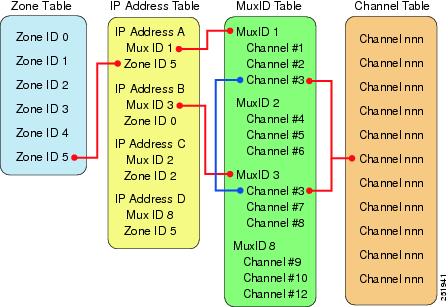
Configuring Address Management and Channel Mapping
To configure CMM to associate video flows with the IP addresses used to transmit video flows and monitor multiplexed channels and ad zones, you must configure four tables in the database used by CMM. You must configure the tables in the order listed here:
1. ![]() AdZone Table—Identifies ad zones defined by the service provider. The ad zones are linked to the IP Address Table.
AdZone Table—Identifies ad zones defined by the service provider. The ad zones are linked to the IP Address Table.
2. ![]() MuxID Table—Describes the channels transmitted in multicast video flows.
MuxID Table—Describes the channels transmitted in multicast video flows.
3. ![]() Channel Table—Specifies details about the channels used to transmit video flows, such as the channel name, type of CODEC used for the channel, and the screen format.
Channel Table—Specifies details about the channels used to transmit video flows, such as the channel name, type of CODEC used for the channel, and the screen format.
4. ![]() IP Address Table—Associates multicast IP addresses with channel names defined in the MuxID Table.
IP Address Table—Associates multicast IP addresses with channel names defined in the MuxID Table.
You can add the AdZone Table, Channel Table, and IP Address Table table into CMM by creating them as CSV files. However, you must manually enter the MuxID Table into CMM.
Note ![]() When you configure Cisco Info Center, you must either provide all four tables as CSV files or enter the data into an Informix database that the Cisco Info Center Object Server reads. If you plan to import the tables into Cisco Info Center as CSV files, name the CSV files as follows
When you configure Cisco Info Center, you must either provide all four tables as CSV files or enter the data into an Informix database that the Cisco Info Center Object Server reads. If you plan to import the tables into Cisco Info Center as CSV files, name the CSV files as follows
- AdZone Table—VAMScmmZONEtable.csv
- MuxID Table—muxid.csv
- Channel Table—channels.csv
- IP Address Table —addresses.csv
For information on importing the CSV files into Cisco Info Center, see Configuring Channel Mapping in Cisco Info Center.
CMM indexes these tables using relational keys that point from entries in one table to entries in the other tables, as shown in Figure 5-1.
Figure 5-1 CMM Database Table Index Relationships
Configuring the Ad Zone Table
Service providers (SPs) can insert national, regional, or local advertising content into a given video channel.This enables the SP to realize increased revenue. Ad zones describe the scope of the network where specific advertisements are inserted.
Ad insertion creates challenges for SPs. In each ad zone, the multicast destination address must be changed to reflect ad modifications. One program can be put into multiple ad zones. It is important to not only track the program in a single ad zone, but also to the program across all ad zones, along with the program state before ad splicing.
The Ad Zone table identifies the IP address (and related video channels) to the ad zone in advertising for that IP flow was inserted.
The table fields are:
•![]() Zone Number—A unique ID created by the SP.
Zone Number—A unique ID created by the SP.
•![]() Zone Name—A unique name describing the ad zone.
Zone Name—A unique name describing the ad zone.
Using CMM, you can either add ad zones individually, or import multiple ad zones in a CSV file having the following format:
ad zone number,ad zone name
For example:
2, My Ad Zone
Cisco recommends using a CSV file, because a CSV version of this table must be added to the Cisco Info Center Object Server or the data must be added to an Informix database on the server.
Configuring the Channel Table
The channel table contains details about the video flows being transported across the IP network. The fields for this table include:
•![]() Channel number
Channel number
A unique number identifying the channel.
•![]() Channel Name
Channel Name
Channel name
•![]() Short name
Short name
•![]() Codec type
Codec type
•![]() Screen format
Screen format
•![]() Service type
Service type
Using CMM, you can either add channels individually, or import multiple channels in a CSV file having the following format:
channel number,channel name,short name,codec type,screen format,service type
For example:
2,CBS,WCBS,MPEG-2,widescreen,SIM
Cisco recommends using a CSV file, because a CSV version of this table must be added to the Cisco Info Center Object Server or the data must be added to an Informix database on the server.
Configuring the MuxID Table
The MuxID table enables one or more channels to be associated in a group. Video flows can be carried in single program transport streams (SPTSs) or multiple program transport streams (MPTSs). MPTS flows aggregate many channels into one IP flow, while SPTS uses a one-to-one mapping between channel and flows. Cisco VAMS supports both types of transport stream.
A MuxID is used to describe the channels in a given flow. For example, MuxID 1 might contain the channel numbers for an MPTS carrying Discovery, ESPN, TNT, and Fox News.
The MuxID table fields are:
•![]() Channel Number: The Channel table key
Channel Number: The Channel table key
•![]() Program ID (PID): A value describing the video and audio of the channel.
Program ID (PID): A value describing the video and audio of the channel.
You cannot import MuxID tables into CMM or export them; however, you must configure the MuxID table manually in the CMM interface, and the same data must be added to the Cisco Info Center Object Server configuration, either as a CSV file, or as an Informix database table.
CMM requires individual entries configured using the GUI. When you create a CSV file to import into Cisco Info Center, use this format:
MuxID,Channel_Number,ProgramID
For example,:
1,1,1
To create a MUX ID in CMM and associate channels and program IDs with it:
Step 1 ![]() Select the Administration tool.
Select the Administration tool.
Step 2 ![]() Click Address Management > Multiplex Table Database.
Click Address Management > Multiplex Table Database.
The Multiplex Table Database page opens.
Step 3 ![]() From the Multiplex Table Database drop-down menu, choose Add Mux ID.
From the Multiplex Table Database drop-down menu, choose Add Mux ID.
Step 4 ![]() Enter a MUX Id and click Add.
Enter a MUX Id and click Add.
Step 5 ![]() From the Multiplex Table Database drop-down menu, choose Configure Mux.
From the Multiplex Table Database drop-down menu, choose Configure Mux.
The Configure MUX window appears.
Step 6 ![]() On the Configure Mux window:
On the Configure Mux window:
a. ![]() From the Select Mux ID drop-down menu, choose the Mux to configure.
From the Select Mux ID drop-down menu, choose the Mux to configure.
b. ![]() On the list of channels, select the channel for the Mux.
On the list of channels, select the channel for the Mux.
The channel appears in the database display for the Mux Id.
c. ![]() Enter the Program ID for the Mux.
Enter the Program ID for the Mux.
Configuring the IP Address Table
To enable CMM to map the video channels that it monitors to the multicast addresses associated with the channels, you must configure the CMM IP address table.
The IP address table associates multicast addresses with video channel information. This enables easy, quick recognition of a channel by name rather than by IP address.
The IP address table that you configure in CMM must be added to the Cisco Info Center Object Server configuration to enable Cisco Info Center to interpret the events it receives from CMM.
The IP Address table contains the following fields:
•![]() IP Address—A unique multicast address.
IP Address—A unique multicast address.
•![]() Description—Information displayed during diagnostics.
Description—Information displayed during diagnostics.
•![]() Ad Zone ID—The Ad Zone Table key.
Ad Zone ID—The Ad Zone Table key.
•![]() MuxID—The MuxID table key.
MuxID—The MuxID table key.
Using CMM, you can either add addresses individually, or import multiple addresses in a comma-separated variables (CSV) file. The CSV file. for the IP address table must have this format:
IP address, description, Ad Zone ID, Mux ID
To import the IP address table into CMM:
Step 1 ![]() In CMM, select the Administration tab.
In CMM, select the Administration tab.
Step 2 ![]() Choose Address Management > Address Database.
Choose Address Management > Address Database.
The IP Address Database window appears.
Step 3 ![]() From the drop-down menu in the Select Action field, select Import Addresses.
From the drop-down menu in the Select Action field, select Import Addresses.
Step 4 ![]() Click the Browse button next to the Import from File field, locate the CSV file for the IP address table, and select it.
Click the Browse button next to the Import from File field, locate the CSV file for the IP address table, and select it.
Step 5 ![]() Click Import.
Click Import.
Discovering CRS-1 Devices in an Out-of-Band Network
If you are using CRS-1 devices in an out-of-band network, the CMM discovery process might not find the routers initially, because Protocol Independent Multicast (PIM) cannot be configured on the virtual addresses that are used for an out-of-band configuration.
As a workaround, you can add host routes on the CMM host that point to the Loopback 0 interfaces on the out-of-band CRS-1 devices and then add the CRS-1 devices using the CMM Add/Rediscover a Single Device function.
To enable discovery of CRS-1 devices in an out-of-band network:
Step 1 ![]() Set up a seed router in the out-of-band network.
Set up a seed router in the out-of-band network.
Step 2 ![]() When you initially perform discovery from the CMM Multicast discovery window, specify the IP address of the seed router in the Seed Router field on the CMM Multicast Discovery window.
When you initially perform discovery from the CMM Multicast discovery window, specify the IP address of the seed router in the Seed Router field on the CMM Multicast Discovery window.
For detailed information on multicast discovery, see the "Getting Started" chapter in the User Guide for Cisco Multicast Manager 2.5:
http://www.cisco.com/en/US/docs/net_mgmt/cisco_multicast_manager/2.5/user/guide/cmm_gs.html
Step 3 ![]() Configure the Loopback 0 interface on the CRS-1 devices.
Configure the Loopback 0 interface on the CRS-1 devices.
Step 4 ![]() Add static routes on the CMM device pointing to the Loopback 0 interfaces on the CRS-1 devices.
Add static routes on the CMM device pointing to the Loopback 0 interfaces on the CRS-1 devices.
Step 5 ![]() Complete these steps to discover each out-of-bound CRS-1 device:
Complete these steps to discover each out-of-bound CRS-1 device:
a. ![]() In Cisco Multicast Manager, select the Administration tool.
In Cisco Multicast Manager, select the Administration tool.
b. ![]() Choose Discovery > Multicast.
Choose Discovery > Multicast.
The Multicast Discovery window appears.
c. ![]() In the Add/Rediscover a Single Device area, enter the host route that you set up for the Loopback 0 interface on the CRS-1.
In the Add/Rediscover a Single Device area, enter the host route that you set up for the Loopback 0 interface on the CRS-1.
d. ![]() Click Add/Rediscover.
Click Add/Rediscover.
Setting Up Troubleshooting Configuration for IP Multicast
Configuring IP multicast configuration settings in CMM for VAMS 2.0 includes the following tasks:
•![]() Configuring BPS/PPS Threshold Monitoring
Configuring BPS/PPS Threshold Monitoring
•![]() Configuring IP Multicast Heartbeat Monitoring
Configuring IP Multicast Heartbeat Monitoring
Configuring BPS/PPS Threshold Monitoring
Cisco VAMS 2.0, which includes CMM 2.5.4. enables polling of flows from Cisco 7600 routers and Cisco 6500 devices without the use of video probes. This is referred to as probeless monitoring.
To configure probeless monitoring, in the domain configuration for the monitored device, specify Telnet as the CLI threshold polling method. Then, on the main SG Polling Configuration page, set up the thresholds that you want to configure for each device.
To set up BPS/PPS Threshold Monitoring:
Step 1 ![]() In the CMM application, from the Multicast Manager home page, select the Administration tool.
In the CMM application, from the Multicast Manager home page, select the Administration tool.
Step 2 ![]() Select Domain Management.
Select Domain Management.
Step 3 ![]() Select add a new domain.
Select add a new domain.
The System Configuration page appears.
Note ![]() To edit an existing domain, select edit next to the desired domain listing.
To edit an existing domain, select edit next to the desired domain listing.
Step 4 ![]() Specify the domain settings as described in "Creating a Domain" in the User Guide for Cisco Multicast Manager 2.5 at the following location:
Specify the domain settings as described in "Creating a Domain" in the User Guide for Cisco Multicast Manager 2.5 at the following location:
http://www.cisco.com/en/US/docs/net_mgmt/cisco_multicast_manager/2.5/user/guide/cmm_gs.html
Step 5 ![]() Complete these steps to enable CLI polling:
Complete these steps to enable CLI polling:
a. ![]() On the System Configuration page, from the drop-down list for CLI Threshold Polling method, select telnet, as shown in Figure 5-2.
On the System Configuration page, from the drop-down list for CLI Threshold Polling method, select telnet, as shown in Figure 5-2.
Figure 5-2 Configuring the CLI Threshold Polling Method
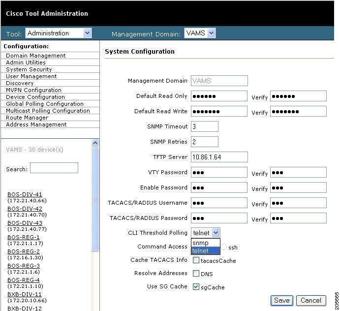
b. ![]() Enter a valid password VTY password in the VTY Password field and in the Verify field.
Enter a valid password VTY password in the VTY Password field and in the Verify field.
c. ![]() Click Save to save the domain configuration.
Click Save to save the domain configuration.
d. ![]() Click the Reporting tab and then click Display All IOS Versions.
Click the Reporting tab and then click Display All IOS Versions.
The IOS Version Info window appears.
e. ![]() Verify that all devices to be used for CLI polling have a valid model listed on the IOS Version Info window.
Verify that all devices to be used for CLI polling have a valid model listed on the IOS Version Info window.
Note ![]() The 7600S chassis might have a model value of "unknown."
The 7600S chassis might have a model value of "unknown."
f. ![]() If the entries for 7600S chassis have a model value of "unknown," complete these steps to download the latest CISCO-PRODUCTS-MIB.oid file from ftp://ftp.cisco.com/pub/mibs/oid/ and then re-run the CMM Discovery process to find any previously unknown devices.
If the entries for 7600S chassis have a model value of "unknown," complete these steps to download the latest CISCO-PRODUCTS-MIB.oid file from ftp://ftp.cisco.com/pub/mibs/oid/ and then re-run the CMM Discovery process to find any previously unknown devices.
- In your browser, go to ftp://ftp.cisco.com/pub/mibs/oid/.
- Download the latest CISCO-PRODUCTS_MIB.oid file.
For a Linux system, download the file to the /usr/local/netman/oid directory.
For a UNIX (Solaris) system, download the file to the /opt/RMSMMT/oid directory.
–![]() Re-run the CMM Discovery process.
Re-run the CMM Discovery process.
g. ![]() Use a text editor to open the rmspollcli.conf file.
Use a text editor to open the rmspollcli.conf file.
On a Linux system, the rmspollcli.conf file is located in the /usr/local/netman/mmtsys/sys directory.
On a UNIX (Solaris) system, the rmspollcli.conf file is in the /opt/RMSMMT/mmtsys/sys directory.
h. ![]() Add entries for the IOS version and chassis type to the rmspollcli.conf file.
Add entries for the IOS version and chassis type to the rmspollcli.conf file.
Example 5-1 shows a sample rmspollcli.conf file.
Example 5-1 Sample rmspollcli.conf file with IOS Version and Chassis Entries
CLIIOS:SXF,SRA,SRB,SRC,SRD
CLICHASSIS:76,65
i. ![]() Save the file.
Save the file.
Step 6 ![]() To configure SG polling and set up PPS/BPS thresholds, select Multicast Polling Configuration > SG Polling - Main.
To configure SG polling and set up PPS/BPS thresholds, select Multicast Polling Configuration > SG Polling - Main.
The main SG Polling Configuration page opens, as shown in Figure 5-3.
Figure 5-3 SG Polling Configuration Page
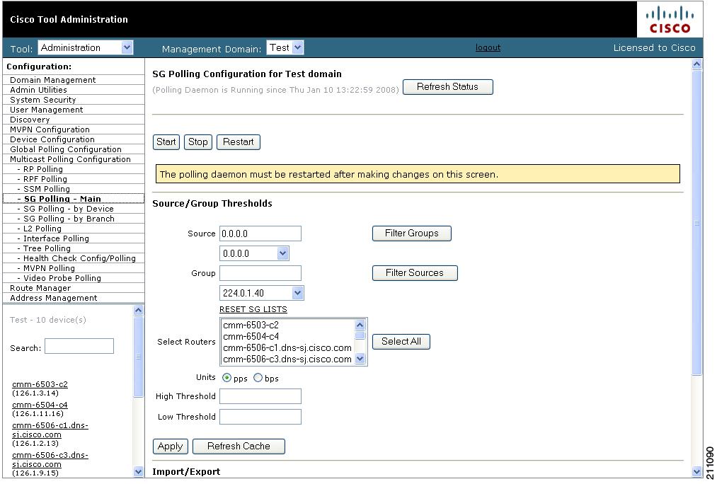
Step 7 ![]() Configure PPS/BPS thresholds as described in the "SG Polling - Main" section of the User Guide for Cisco Multicast Manager 2.5 at the following location:
Configure PPS/BPS thresholds as described in the "SG Polling - Main" section of the User Guide for Cisco Multicast Manager 2.5 at the following location:
Configuring Tree Polling
Multicast trees can change due to network outages or in response to establishment of more optimal flow paths. Because tree changes might impact video quality immediately or in the future, it is important for network operators to be notified of changes in multicast trees.
To configure tree polling, you must first create a trace file by drawing a multicast tree and saving it. The trace filename must use the specified format for the CMM Tree Changed events to be correlated properly in Cisco Info Center. You can then use the saved tree as a baseline for configuring tree polling.
The trace filename that you specify must have this format:
<channel_name>_<ad_zone>_<Mcast-Group>_<source-IP>
where channel_name is the name of the channel, ad_zone is the name of the Ad zone, Mcast-Group is the address of the multicast group, and source-IP is the IP address of the source. For example:
PBS_National_232-0-1-32_12-101-2-18
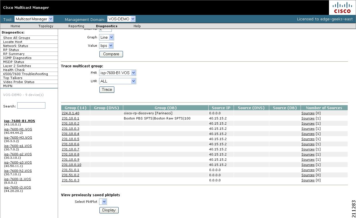
To configure tree polling:
Step 1 ![]() Start the Diagnostics tool.
Start the Diagnostics tool.
Step 2 ![]() Click Show All Groups.
Click Show All Groups.
The Multicast Diagnostics page appears, as shown in Figure 5-4.
Figure 5-4 Multicast Diagnostics Page
Step 3 ![]() From the drop-down list below the Source field in the Set Source and Group to Work On pane, select a source to work on.
From the drop-down list below the Source field in the Set Source and Group to Work On pane, select a source to work on.
Step 4 ![]() From the drop-down list below the Group field in the Set Source and Group to Work On pane, select a group to work on.
From the drop-down list below the Group field in the Set Source and Group to Work On pane, select a group to work on.
The Multicast Diagnostics page appears with the source and group selected.
Step 5 ![]() For additional details, see the "Show All Groups" section in the User Guide for Cisco Multicast Manager 2.5 at this location:
For additional details, see the "Show All Groups" section in the User Guide for Cisco Multicast Manager 2.5 at this location:
http://www.cisco.com/en/US/docs/net_mgmt/cisco_multicast_manager/2.5/user/guide/cmm_dt.html
CMM draws a tree diagram of the tree.
Step 6 ![]() To save the trace to use as a baseline for tree polling, in the Trace File field, enter a name the trace file, and then click Save As.
To save the trace to use as a baseline for tree polling, in the Trace File field, enter a name the trace file, and then click Save As.
Note ![]() The trace filename that you specify must have this format:
The trace filename that you specify must have this format:
<channel_name>_<ad_zone>_<Mcast-Group>_<source-IP>
where channel_name is the name of the channel, ad_zone is the name of the Ad zone, Mcast-Group is the address of the multicast group, and source-IP is the IP address of the source. For example:
PBS_National_232-0-1-32_12-101-2-18
Step 7 ![]() To set up tree polling for the saved baseline, complete these steps:
To set up tree polling for the saved baseline, complete these steps:
a. ![]() Select the Administration tool.
Select the Administration tool.
b. ![]() Select Multicast Polling Configuration > Tree Polling.
Select Multicast Polling Configuration > Tree Polling.
The Tree Polling Configuration page opens, as shown in Figure 5-5.
Figure 5-5 Tree Polling Configuration Page
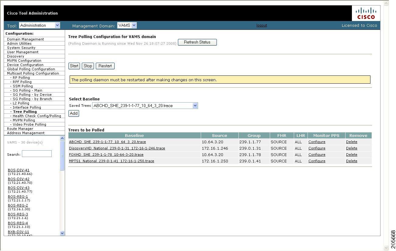
The Tree Polling Configuration page contains the following fields and buttons:
c. ![]() To monitor a tree, from the drop-down menu in the Saved Trees field, select the tree name, and click Add.
To monitor a tree, from the drop-down menu in the Saved Trees field, select the tree name, and click Add.
d. ![]() To specify how often the tree is polled:
To specify how often the tree is polled:
–![]() Click Global Polling Configuration.
Click Global Polling Configuration.
The Global Polling Configuration Page appears.
–![]() Click Tree Polling Interval, and on the dialog that appears, specify the time interval for tree polling.
Click Tree Polling Interval, and on the dialog that appears, specify the time interval for tree polling.
–![]() Save your changes.
Save your changes.
–![]() Click Set to save your global polling configuration.
Click Set to save your global polling configuration.
The tree is drawn in the background for every interval that you set up for tree polling. This tree is compared with the tree saved in the database. If it is different, a trap is sent, and a report is generated.
Configuring Health Checks
The CMM application provides the ability to set up health checks that check and report on the status of critical components of your IP multicast network. Health checks can check the status of RPs, MSDP peering, the presence of sources and groups, and the status of multicast trees.
You should create a health check for every important source and group in your multicast network.
To configure health check polling:
Step 1 ![]() Select the Administration tool.
Select the Administration tool.
Step 2 ![]() Select Multicast Polling Configuration > Health Check Config/Polling.
Select Multicast Polling Configuration > Health Check Config/Polling.
The Health Check Config/Polling page opens, as shown in Figure 5-6.
Figure 5-6 Health Check Polling Configuration Page
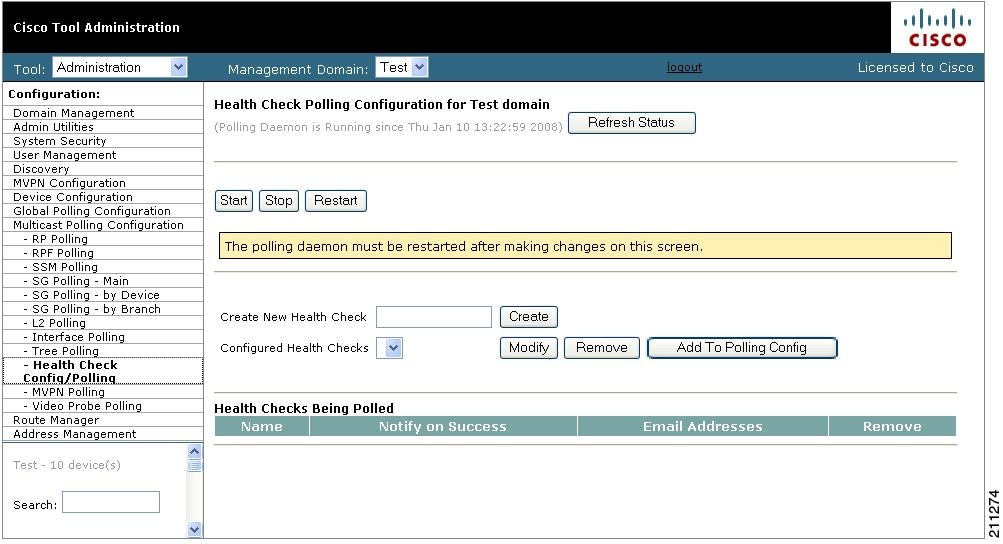
The Health Check Config/Polling page contains the following fields and buttons:
Configuring IP Multicast Heartbeat Monitoring
Cisco routers can monitor the data plane of a multicast group and detect when that group is no longer receiving multicast packets. This is useful to confirm that the traffic stream is active.
To set up heartbeat monitoring requires that a downstream router or host has joined a multicast group or a static IGMP has been set; a data path must be established through the router that is configured for heartbeat monitoring.
Configuring heartbeat monitoring consists of two steps:
1. ![]() Configuring IP multicast on a router.
Configuring IP multicast on a router.
2. ![]() Enabling monitoring for the router.
Enabling monitoring for the router.
Configuring IP Multicast Heartbeat on the Router
To configure IP multicast heartbeat on a router for which you want to enable IP multicast heartbeat, enter the following commands:
snmp-server enable traps ipmulticast
ip multicast heartbeat <ip_address> <minimum_number> <intervals> <interval_length>
where ip_address is the IP address of the router, minimum_number is the minimum number of intervals, intervals is the number of intervals, and interval_length is the length of the intervals in seconds.
The following is an example configuration of the ip multicast heartbeat command:
snmp-server enable traps ipmulticast-heartbeat
ip multicast heartbeat 224.0.1.53 1 1 10
Configuring Video Probes
Each video probe in Cisco VAMS 2.0 monitors various parameters of the video flow through the network. For example, you might configure a video probe to monitor the amount of jitter or delay in a video stream.
For each video probe deployed in the network, you must configure the thresholds for the conditions that you want to monitor. Only probes not supported by CMM should trap directly to Cisco Info Center—for these probes you must also configure the video probes to forward traps to Cisco Info Center. (See the probe documentation for information on adding the Cisco Info Center IP addresses and related SNMP information to the video probe settings.)
After you configure the video probe, if a monitored condition exceeds a configured threshold, the probe sends a corresponding trap to Cisco Info Center, which shows the event in the TBSM GUI and the Webtop GUI.
Note ![]() CMM 2.5.4 will poll the IneoQuest probes even though the probes may also be sending traps to Cisco Info Center.
CMM 2.5.4 will poll the IneoQuest probes even though the probes may also be sending traps to Cisco Info Center.
Bridge Technologies Video Probe
You can configure the Bridge Technologies video probe to send traps directly to Cisco Info Center. To configure the Bridge Technologies video probe for operation in the video transport network, see the documentation that comes with the product. The VB120 Broadcast IP-Probe User's Manual v. 4.0 assists the network planner when integrating the Bridge Technologies video probes with Cisco VAMS 2.0.
IneoQuest Video Probe
You can configure the IneoQuest video probe to send alerts to CMM and configure CMM to forward the alerts to Cisco Info Center.
To configure the IneoQuest video probe for operation in the video transport network, see the documentation that comes with the product. These documents assist the network planner when integrating the IneoQuest video probes with Cisco VAMS 2.0:
•![]() Hardware User's Guide
Hardware User's Guide
•![]() IQMediaAnalyzer Application User's Guide
IQMediaAnalyzer Application User's Guide
Mixed Signals Video Probe
You can configure the Mixed Signals video probe to send traps directly to Cisco Info Center. To configure the Mixed Signals video probe for operation in the video transport network, see the documentation that comes with the product. The Mixed Signals Sentry Digital Content Monitor User Guide assists the network planner when integrating the Mixed Signals video probes with Cisco VAMS 2.0.
PixelMetrix Video Probe
You can configure the Pixelmetrix video probe to send traps directly to Cisco Info Center. To configure the PixelMetrix video probe for operation in the video transport network, see the documentation that comes with the product. The DVStation-IP-3 User Manual, Software Version 4.17 assists the network planner when integrating the PixelMetrix video probes with Cisco VAMS 2.0.
Tektronix Video Probe
You can configure the Tektronix video probe to send traps directly to Cisco ANA or to Cisco Info Center. To configure the Tektronix video probe for operation in the video transport network, see the documentation that comes with the product. These documents assist the network planner when integrating the Tektronix video probes with Cisco VAMS 2.0.
•![]() MTM400 MPEG Transport Stream Monitor User Manual
MTM400 MPEG Transport Stream Monitor User Manual
•![]() MTM400 MPEG Transport Stream Monitor Technical Reference
MTM400 MPEG Transport Stream Monitor Technical Reference
•![]() MTM400 MPEG Transport Stream Monitor Programmer Manual
MTM400 MPEG Transport Stream Monitor Programmer Manual
Running the Setup for IPTV Script
The Setup for IPTV activation script sets up network configuration parameters for the Cisco devices in Cisco VAMS 2.0.
The script runs:
•![]() ANA startup.
ANA startup.
•![]() Every two hours.
Every two hours.
•![]() Whenever the managed device reloads.
Whenever the managed device reloads.
•![]() When you activate it in ANA NetworkVision (see procedure).
When you activate it in ANA NetworkVision (see procedure).
The hourly run checks the IPTV configuration of the managed VNEs. If a VNE does not have the expected IPTV configuration, the script applies the IPTV configuration parameters to the device.
Note ![]() Configure the supported devices and load them with IPTV-enabled IOS images. The IPTV script does not recognize the devices without IPTV-enabled IOS images. (See the "Before You Install" section on page 3-1.)
Configure the supported devices and load them with IPTV-enabled IOS images. The IPTV script does not recognize the devices without IPTV-enabled IOS images. (See the "Before You Install" section on page 3-1.)
To manually run the IPTV activation script for setup:
Step 1 ![]() Log in to ANA NetworkVision.
Log in to ANA NetworkVision.
Step 2 ![]() Right-click a VNE in the network map.
Right-click a VNE in the network map.
Step 3 ![]() In the right-click menu, choose Management > Setup for IPTV.
In the right-click menu, choose Management > Setup for IPTV.
Step 4 ![]() In the Setup for IPTV window, click the Execute button.
In the Setup for IPTV window, click the Execute button.
The result of the script appears in the same window under the Result tab.
Note ![]() If the selected VNE already has its IPTV configuration, the result indicates ALREADY CREATED, and the script does not run.
If the selected VNE already has its IPTV configuration, the result indicates ALREADY CREATED, and the script does not run.
Running the Cleanup from IPTV Script
You run the Cleanup from IPTV activation script when you want to remove the IPTV extensions from a VNE that is in the Cisco VAMS 2.0. When you remove the extensions, the VNE will not be able to process the IPTV requests.
To run the Cleanup from IPTV script:
Step 1 ![]() Log in to ANA NetworkVision.
Log in to ANA NetworkVision.
Step 2 ![]() Right-click the VNE in the network map.
Right-click the VNE in the network map.
Step 3 ![]() In the right-click menu, choose Management > Cleanup from IPTV.
In the right-click menu, choose Management > Cleanup from IPTV.
The Cleanup from IPTV script runs and removes the IPTV extensions from the selected VNE.
Configuring the ROSA NMS
This section describes specific ROSA NMS configuration tasks that are required to configure the application to work with Cisco VAMS 2.0. For more detailed information, see:
•![]() The README file for the ROSA Copernicus NMS. This file launches automatically when you insert the ROSA NMS installation CD in your Windows server or Windows workstation.
The README file for the ROSA Copernicus NMS. This file launches automatically when you insert the ROSA NMS installation CD in your Windows server or Windows workstation.
•![]() The ROSA Network Management System User's Guide, Version 3.0 Build 18. This document is provided in PDF format on CD 1 of the ROSA NMS installation media.
The ROSA Network Management System User's Guide, Version 3.0 Build 18. This document is provided in PDF format on CD 1 of the ROSA NMS installation media.
•![]() SNMP Agent Users Guide, Task Driver for ROSA 3.0. This document is provided on the Documentation CD for the ROSA Copernicus Network Management System server.
SNMP Agent Users Guide, Task Driver for ROSA 3.0. This document is provided on the Documentation CD for the ROSA Copernicus Network Management System server.
This section describes:
•![]() Configuring a Northbound Trap Destination
Configuring a Northbound Trap Destination
•![]() Ensuring That the Alarm Suppression Rule is Disabled
Ensuring That the Alarm Suppression Rule is Disabled
Configuring the SNMP Agent
ROSA Copernicus Network Management System server software includes SNMP agent software for the ROSA system. To enable Cisco VAMS 2.0 monitoring of ROSA NMS events, you must configure the SNMP agent to send ROSA NMS traps to Cisco Info Center
To configure the SNMP Agent for the Copernicus NMS server:
Step 1 ![]() Install the SNMP agent on your ROSA Copernicus NMS server.
Install the SNMP agent on your ROSA Copernicus NMS server.
For detailed installation instructions, refer to "Installing the SNMP Agent Task Driver" in the SNMP Agent Users Guide, Task Driver for ROSA 3.0. This document is provided on the Documentation CD for the ROSA Copernicus Network Management System server.
Step 2 ![]() On the ROSA client, go to the Server Explorer window.
On the ROSA client, go to the Server Explorer window.
Step 3 ![]() Select Config > Drivers.
Select Config > Drivers.
The Installed Drivers dialog appears.
Step 4 ![]() Click the Install button.
Click the Install button.
A list of installed drivers appears, as shown in Figure 5-7:
Figure 5-7 SNMP Install Screen
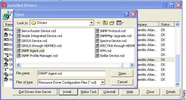
Step 5 ![]() Highlight the SNMP Agent.rsd driver and click Open.
Highlight the SNMP Agent.rsd driver and click Open.
The Make Task dialog appears.
Step 6 ![]() On the Make Task dialog, enter a task name, such as SNMP Agent, and then click OK.
On the Make Task dialog, enter a task name, such as SNMP Agent, and then click OK.
The SNMP Agent task now appears in the Global Inventory directory on the ROSA interface.
Configuring a Northbound Trap Destination
After you add the SNMP task, you must specify a northbound trap destination to configure ROSA to send SNMP traps to Cisco Info Server.
Complete these steps to configure the northbound trap destination:
Step 1 ![]() On the ROSA interface, click the Global tab.
On the ROSA interface, click the Global tab.
Step 2 ![]() In the Global Inventory directory tree, right-click the SNMP task, for example SNMP Agent.
In the Global Inventory directory tree, right-click the SNMP task, for example SNMP Agent.
Step 3 ![]() From the pull-down menu for the task, select Properties.
From the pull-down menu for the task, select Properties.
The SNMP User Agent dialog appears.
Step 4 ![]() Click the Communities tab.
Click the Communities tab.
The Communities dialog appears, as shown in Figure 5-8:
Figure 5-8 Northbound Configuration Screen
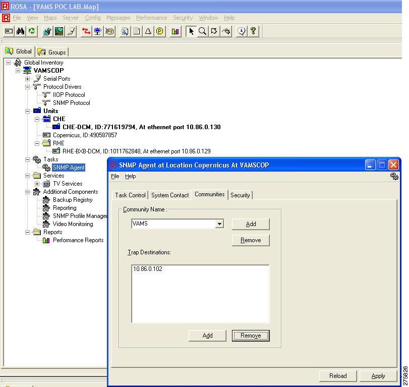
Step 5 ![]() In the Community Name field, enter the name of an SNMP community for the SNMP agent, for example, VAMS.
In the Community Name field, enter the name of an SNMP community for the SNMP agent, for example, VAMS.
Step 6 ![]() Click Apply.
Click Apply.
Step 7 ![]() After you have added the community for VAMS, complete these steps to add a northbound trap destination.
After you have added the community for VAMS, complete these steps to add a northbound trap destination.
a. ![]() On the SNMP dialog, click the Communities tab.
On the SNMP dialog, click the Communities tab.
The Add Trap Destination dialog appears.
b. ![]() Enter the IP address of the Cisco Info Center Object Server.
Enter the IP address of the Cisco Info Center Object Server.
c. ![]() Click OK.
Click OK.
Step 8 ![]() Click Apply.
Click Apply.
The SNMP Agent is now configured to forward traps to Cisco Info Center.
Ensuring That the Alarm Suppression Rule is Disabled
By default, the ROSA NMS is configured to disable the Repetitive Alarm Distribution Rule. However, if your ROSA NMS has this rule enabled, ROSA events might not clear automatically in Cisco Info Center, because the Repetitive Alarm Distribution Rule causes the ROSA NMS to generate Summary messages in the place of individual alarm messages. Because these Summary messages use incremented trpMSGID values, Cisco Info Center cannot associate them with the initial alarm event and clear that event.
To prevent this situation from occurring, if the ROSA NMS has the Repetitive Alarm Distribution Rule configured, Cisco recommends that you perform the following steps:
•![]() Disable the Repetitive Alarm Distribution Rule—See Disabling the Repetitive Alarm Distribution Rule.
Disable the Repetitive Alarm Distribution Rule—See Disabling the Repetitive Alarm Distribution Rule.
•![]() Configure End Debouncing Timers on the DCM—See Configuring End Debouncing Timers on the DCM.
Configure End Debouncing Timers on the DCM—See Configuring End Debouncing Timers on the DCM.
Disabling the Repetitive Alarm Distribution Rule
Complete these steps to disable the Repetitive Alarm Distribution Rule on the ROSA NMS:
Step 1 ![]() In the Server Explorer or Group Explorer directory tree on the ROSA system, select the server on which message rule scripts are added and from the pull-down menu, select Rules.
In the Server Explorer or Group Explorer directory tree on the ROSA system, select the server on which message rule scripts are added and from the pull-down menu, select Rules.
The Message Rules dialog appears, as shown in Figure 5-9:
Figure 5-9 ROSA Message Rules
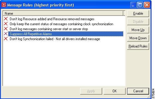
Step 2 ![]() Check the Suppress All Repetitive Alarms check box.
Check the Suppress All Repetitive Alarms check box.
Step 3 ![]() Check the check boxes next to any other alarms that you want to disable.
Check the check boxes next to any other alarms that you want to disable.
Step 4 ![]() Click Disable.
Click Disable.
Configuring End Debouncing Timers on the DCM
Enabling debouncing timers on the DCM will not completely resolve the issue of nonclearing ROSA events in Cisco Info Center if the ROSA Alarm Suppression Rule is enabled. However, properly configured DCM debouncing timers should greatly reduce the possibility of DCM events not automatically clearing in Cisco Info Center when the ROSA Alarm Suppression Rule is enabled. If DCM debouncing timers are configured, situations where the ROSA Alarm Suppression rule is needed are reduced, because the DCM will not generate as many alerts.
To configure End Debouncing timers:
Step 1 ![]() On the web browser user interface of the DCM, click the Configuration link.
On the web browser user interface of the DCM, click the Configuration link.
The Configuration page appears.
Step 2 ![]() In the DCM configuration tree, double-click on the interface card for which alarm settings must be configured.
In the DCM configuration tree, double-click on the interface card for which alarm settings must be configured.
The Configuration-Interface page for the selected interface card appears.
Step 3 ![]() Click the Alarms link.
Click the Alarms link.
The Configuration-Alarms dialog for the specified interface card appears, as shown in Figure 5-10.
Figure 5-10 ROSA End Debouncing Timer
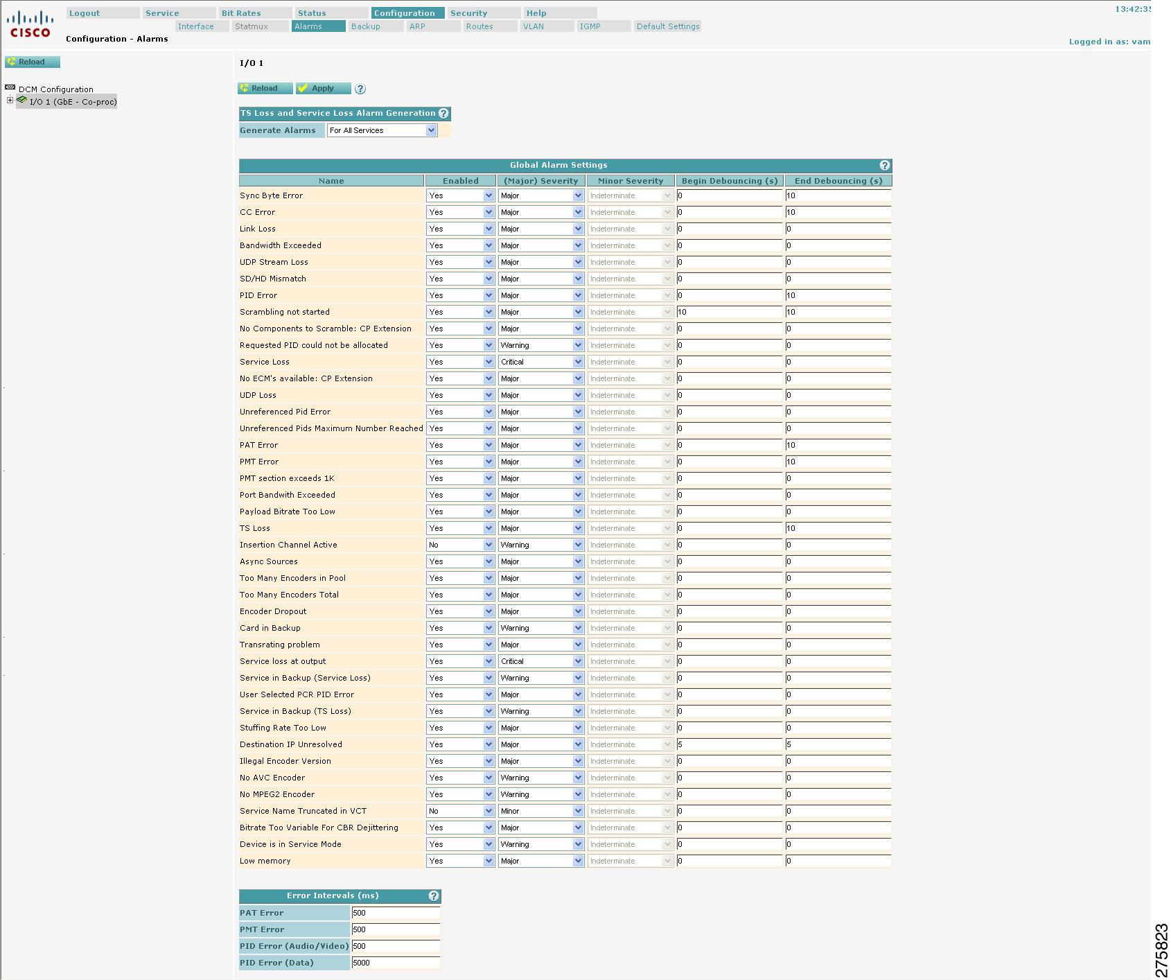
Step 4 ![]() Enter a timer value in the End Debouncing column for each enabled alarm. Make sure that you enter values for the following alarms:
Enter a timer value in the End Debouncing column for each enabled alarm. Make sure that you enter values for the following alarms:
•![]() Sync Byte Error
Sync Byte Error
•![]() CC Error
CC Error
•![]() PID Error
PID Error
•![]() Scrambling not started
Scrambling not started
•![]() PAT Error
PAT Error
•![]() PMT Error
PMT Error
•![]() TS Loss
TS Loss
Step 5 ![]() Click Apply
Click Apply
Configuring Cisco Info Center
The Cisco Info Center configuration includes:
•![]() Configuring Channel Mapping in Cisco Info Center
Configuring Channel Mapping in Cisco Info Center
•![]() Configuring Cisco Info Center to Launch CMM and Flow Trace
Configuring Cisco Info Center to Launch CMM and Flow Trace
•![]() Installing IBM Tivoli Netcool View for ANA
Installing IBM Tivoli Netcool View for ANA
Configuring Channel Mapping in Cisco Info Center
To configure channel mapping in Cisco Info Center, you must import the channel mapping tables that have been created in CMM into Cisco Info Center. You can do this in two ways, by:
•![]() Placing CSV files containing the table data on the host that is running the Object Server.
Placing CSV files containing the table data on the host that is running the Object Server.
•![]() Adding the table data to an Informix database that the Object Server reads.
Adding the table data to an Informix database that the Object Server reads.
Copying Channel Mapping Tables to the Object Server
When you configured Cisco Multicast Manager for address management and channel mapping as described in Configuring Address Management and Channel Mapping, you created four CSV files:
•![]() IP Address Table —addresses.csv
IP Address Table —addresses.csv
•![]() Channel Table—channels.csv
Channel Table—channels.csv
•![]() Multiplex (MuxID) Table—muxid.csv
Multiplex (MuxID) Table—muxid.csv
•![]() AdZone Table—VAMScmmZONEtable.csv
AdZone Table—VAMScmmZONEtable.csv
To enable the Object Server to read these tables, copy the tables to the following directory on the Object Server host:
$NCHOME/cmm/
Note ![]() You can also enter the table database into an Informix database on the Object Server. If you will use this method, please consult with Cisco Advanced Services for assistance.
You can also enter the table database into an Informix database on the Object Server. If you will use this method, please consult with Cisco Advanced Services for assistance.
Verifying the Channel Mapping Database
After you have imported the channel mapping database into Cisco Info Center, complete these steps to verify that the database imported correctly:
Step 1 ![]() In your web browser, enter the following address:
In your web browser, enter the following address:
http://cic_ip_address:8081/nci
where cic_ip_address is the IP address of the Impact installation.
The Netcool Impact start window opens.
Step 2 ![]() From the pull-down menu at the top of the display, choose NCI:NCICLUSTER.
From the pull-down menu at the top of the display, choose NCI:NCICLUSTER.
Step 3 ![]() Click the Global tab at the left of the page.
Click the Global tab at the left of the page.
Step 4 ![]() Click Data Types.
Click Data Types.
A list of Data Sources appears, as shown in Figure 5-11.
Figure 5-11 Cisco Multicast Manager Data Sources in Netcool Impact

Step 5 ![]() Click CMM_Addresses to view the CMM_Addresses data type.
Click CMM_Addresses to view the CMM_Addresses data type.
The Edit page for the CMM_Addresses data type appears.
Step 6 ![]() Click the View Data Items for CMM_Addresses icon next to the CMM_Addresses listing (the leftmost icon) to view the data elements that you provided in the addresses.csv file.
Click the View Data Items for CMM_Addresses icon next to the CMM_Addresses listing (the leftmost icon) to view the data elements that you provided in the addresses.csv file.
Step 7 ![]() Verify that the information is correct.
Verify that the information is correct.
Step 8 ![]() Click the CMM_Channels data type in the Data Types listing to view the Edit page for the CMM_Channels data type.
Click the CMM_Channels data type in the Data Types listing to view the Edit page for the CMM_Channels data type.
Step 9 ![]() On the Edit page for the CMM_Channels data type, click the View Data Items for CMM_Channels icon and verify the data elements that you provided in the addresses.csv file.
On the Edit page for the CMM_Channels data type, click the View Data Items for CMM_Channels icon and verify the data elements that you provided in the addresses.csv file.
Step 10 ![]() Click the CMM_IPDB data type in the Data Types listing to view the Edit page and data items for the CMM_IPDB data type.
Click the CMM_IPDB data type in the Data Types listing to view the Edit page and data items for the CMM_IPDB data type.
The information for this data type should be identical to the information for the CMM_Addresses data type.
Step 11 ![]() Click the CMM_MUXDB data type in the Data Types listing to view the Edit page for the CMM_MUXDB data type.
Click the CMM_MUXDB data type in the Data Types listing to view the Edit page for the CMM_MUXDB data type.
Step 12 ![]() On the Edit page for the CMM_MUXDB data type, click the View Data Items for CMM_MUXDB icon and verify the data elements that you provided in the muxid.csv file.
On the Edit page for the CMM_MUXDB data type, click the View Data Items for CMM_MUXDB icon and verify the data elements that you provided in the muxid.csv file.
Creating TBSM Service Templates for Cisco VAMS
To enable TBSM to display and process VAMS alerts, you must configure service templates in TBSM. Configuring TBSM templates involves these steps:
•![]() Creating a Multicast Service Template
Creating a Multicast Service Template
•![]() Creating an Autopopulation Rule
Creating an Autopopulation Rule
Creating a Multicast Service Template
Complete these steps to create a multicast service template.
Step 1 ![]() Log in to TBSM.
Log in to TBSM.
Step 2 ![]() From the drop-down menu at the top of the TBSM window, select Service Administration.
From the drop-down menu at the top of the TBSM window, select Service Administration.
Step 3 ![]() Click the Templates tab in the left pane.
Click the Templates tab in the left pane.
The Templates directory tree appears.
Step 4 ![]() Click the Create New Template icon above the Templates directory tree.
Click the Create New Template icon above the Templates directory tree.
The Service Administration Edit Template window opens, as shown in Figure 5-12.
Figure 5-12 Service Administration—Edit Templates Window
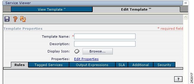
Step 5 ![]() Enter the template name; for example, Multicast_Template.
Enter the template name; for example, Multicast_Template.
Step 6 ![]() Click the disk icon to save the template.
Click the disk icon to save the template.
Step 7 ![]() Click the Incoming Status Rule icon.
Click the Incoming Status Rule icon.
Step 8 ![]() Click the Based on a Good, Marginal, or Bad Threshold radio button and then click OK.
Click the Based on a Good, Marginal, or Bad Threshold radio button and then click OK.
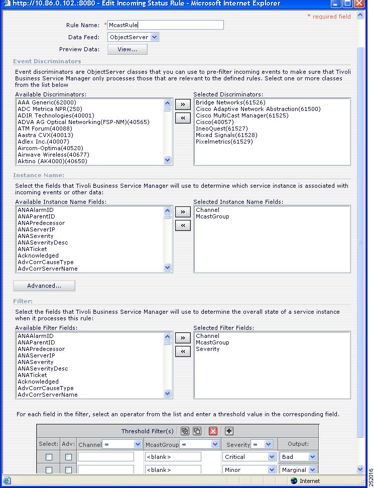
The Edit Incoming Status Rule page opens, as shown in Figure 5-13.
Step 9 ![]() On the Edit Incoming Status Rule page, complete these steps:
On the Edit Incoming Status Rule page, complete these steps:
a. ![]() Enter a rule name, for example McastRule.
Enter a rule name, for example McastRule.
b. ![]() From the list of Available Discriminators, select the discriminators as shown in Figure 5-13.
From the list of Available Discriminators, select the discriminators as shown in Figure 5-13.
c. ![]() From the list of Available Instance Name Fields, select Instance Name fields as shown in Figure 5-13.
From the list of Available Instance Name Fields, select Instance Name fields as shown in Figure 5-13.
d. ![]() From the list of Available Filter Fields, select Filter Fields as shown in Figure 5-13.
From the list of Available Filter Fields, select Filter Fields as shown in Figure 5-13.
Figure 5-13 TBSM Service Administration—Editing the MCast Rule
e. ![]() Click the disk icon to save the rule.
Click the disk icon to save the rule.
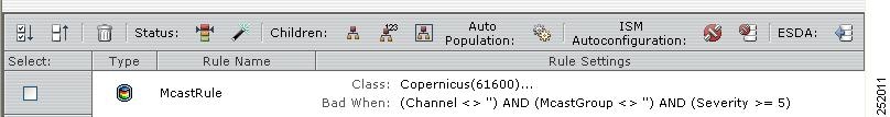
After the rule is saved, TBSM displays the rule in the list of rules for the template, as shown in Figure 5-14.
Figure 5-14 Mcast Rule after Configuration
Creating a Channel Template
Complete these steps to create a Channel template:
Step 1 ![]() On the TBSM Templates window, click the Create New Template icon.
On the TBSM Templates window, click the Create New Template icon.
The Edit Template window opens.
Step 2 ![]() In the Template Name field, enter Channel.
In the Template Name field, enter Channel.
Step 3 ![]() Click the Browse button next to the Display Icon label and select the computer screen icon.
Click the Browse button next to the Display Icon label and select the computer screen icon.
Step 4 ![]() Click the disk icon to save the template.
Click the disk icon to save the template.
Step 5 ![]() In the list of icons for Children, click the Create Good, Marginal, Bad Aggregation rule icon.
In the list of icons for Children, click the Create Good, Marginal, Bad Aggregation rule icon.
The edit dialog for a Good, Marginal, Bad Aggregation Rule appears, as shown in Figure 5-15.
Figure 5-15 TBSM Service Administration—Editing the Channel Rule
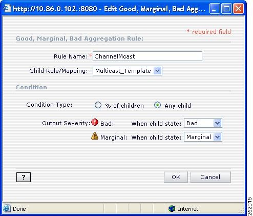
Step 6 ![]() Enter the rule information as shown in Figure 5-15 and click OK.
Enter the rule information as shown in Figure 5-15 and click OK.
The ChannelMcast rule appears in the list of rules for the template.
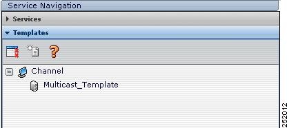
Step 7 ![]() On the Edit Template window, click the disk icon to save the template.
On the Edit Template window, click the disk icon to save the template.
The Templates directory tree now shows the new template, as shown in Figure 5-16.
Figure 5-16 Multicast Template after Saving the Channel Rule
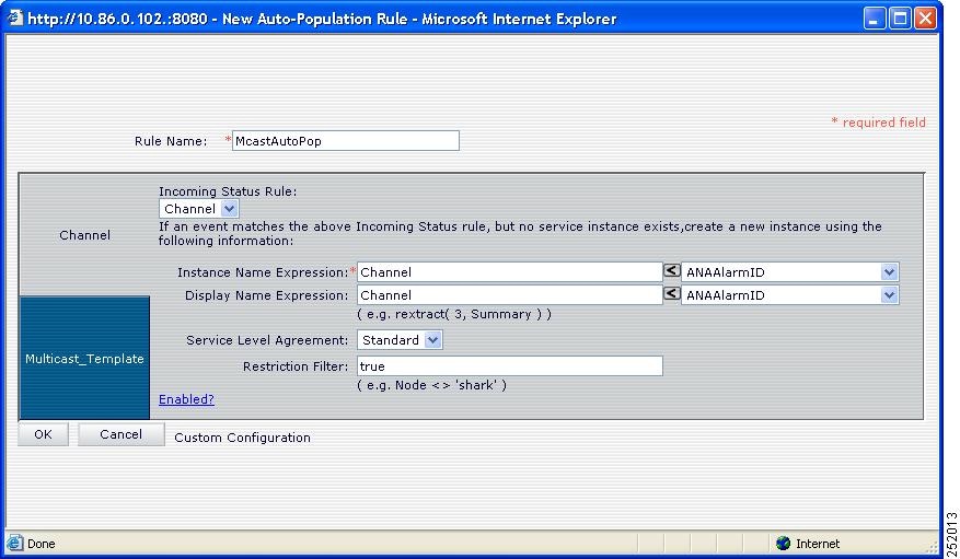
Creating an Autopopulation Rule
To enable TBSM to populate the fields for VAMS alerts, you must create an autopopulation rule for the Multicast Template. Complete these steps to create an autopopulation rule:
Step 1 ![]() On the TBSM Templates window, click Multicast_Template.
On the TBSM Templates window, click Multicast_Template.
Step 2 ![]() On the Edit Template tab, click the Create Autopopulation Rule icon.
On the Edit Template tab, click the Create Autopopulation Rule icon.
A dialog for creating the autopopulation rule appears, as shown in Figure 5-17.
Figure 5-17 Creating an Autopopulation Rule for the Multicast Template
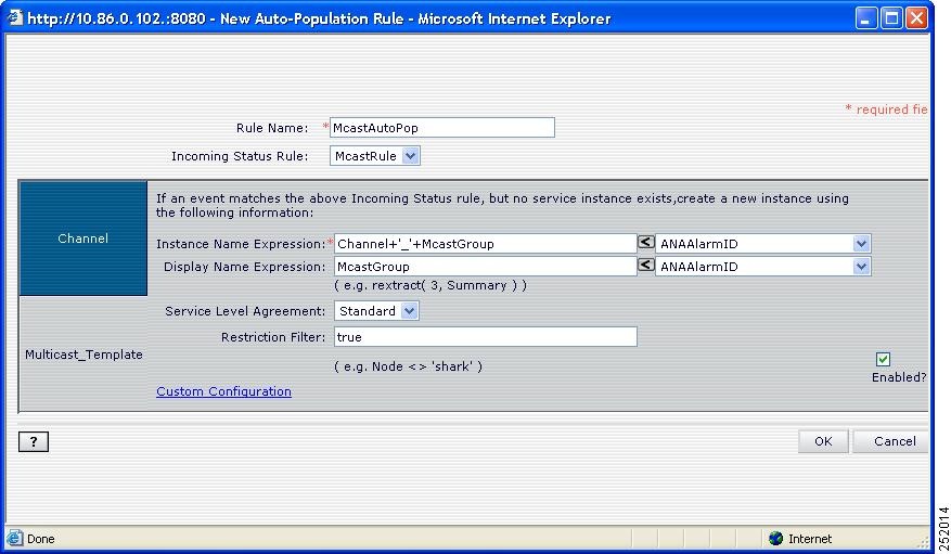
Step 3 ![]() Enter information for the autopopulation rule as shown in Figure 5-17.
Enter information for the autopopulation rule as shown in Figure 5-17.
Step 4 ![]() Click the Channel tab at the upper left of the input area.
Click the Channel tab at the upper left of the input area.
A dialog appears for editing the status rule for the Channel template, as shown in Figure 5-18.
Figure 5-18 Entering Channel Details for the Autopopulation Rule
Step 5 ![]() Enter the Channel details as shown in Figure 5-18.
Enter the Channel details as shown in Figure 5-18.
Step 6 ![]() Click OK to save the Channel details.
Click OK to save the Channel details.
Step 7 ![]() Click OK to save the autopopulation rule.
Click OK to save the autopopulation rule.
Configuring Cisco Info Center to Launch CMM and Flow Trace
Configuration of Cisco Info Center to launch CMM and CMM flow trace involves two steps:
•![]() Editing CGI Scripts to Launch CMM Utilities
Editing CGI Scripts to Launch CMM Utilities
•![]() Adding CMM Menu and Tool Items
Adding CMM Menu and Tool Items
Editing CGI Scripts to Launch CMM Utilities
When users view VAMS events generated by CMM, users can make menu selections that launch CMM to enable further troubleshooting of the event or that launch CMM flowtrace to do a flow trace on the event.
To enable launch of CMM from within the Webtop or TBSM GUI, when you install Cisco VAMS 2.0, two .cgi scripts are installed in the /opt/vams/etc/webtop/cgi-bin directory:
•![]() launch_cmm.cgi—Launches the CMM GUI.
launch_cmm.cgi—Launches the CMM GUI.
•![]() launch_CMM_flowtrace.cgi—Launches CMM and initiates a flow trace.
launch_CMM_flowtrace.cgi—Launches CMM and initiates a flow trace.
Complete these steps to edit the CGI scripts that launch CMM utilities:
Step 1 ![]() On the Cisco Info Center host, go to the following directory:
On the Cisco Info Center host, go to the following directory:
/opt/vams/etc/webtop/cgi-bin
Step 2 ![]() Edit the launch_cmm.cgi script.
Edit the launch_cmm.cgi script.
Step 3 ![]() Locate the following line:
Locate the following line:
my $URL = "https://cmm-ip-address:8080
Step 4 ![]() Change cmm-ip-address to specify the IP address of the CMM server in your VAMS installation.
Change cmm-ip-address to specify the IP address of the CMM server in your VAMS installation.
Step 5 ![]() Save the file.
Save the file.
Step 6 ![]() Edit the launch_cmm_flowtrace.cgi script.
Edit the launch_cmm_flowtrace.cgi script.
Step 7 ![]() Locate the following line:
Locate the following line:
my $URL = "https://cmm-ip-address:8080/perl/strace.pl?"
Step 8 ![]() Change cmm-ip-address to specify the IP address of the CMM server in your VAMS installation.
Change cmm-ip-address to specify the IP address of the CMM server in your VAMS installation.
Step 9 ![]() Save the file.
Save the file.
Adding CMM Menu and Tool Items
This section describes how to modify TBSM to launch CMM and CMM flowtrace.
Adding the CMM Tools
Complete these steps to add the CMM tools to the Cisco Info Center configuration:
Step 1 ![]() Log in to TBSM.
Log in to TBSM.
Step 2 ![]() From the drop-down list at the top of the TBSM start page, choose Webtop Admin.
From the drop-down list at the top of the TBSM start page, choose Webtop Admin.
Webtop launches, and the main Webtop menu appears.
Step 3 ![]() On the Webtop menu, click Tools.
On the Webtop menu, click Tools.
The Webtop Tools window appears. The menu lists the previously configured Webtop tools.
Step 4 ![]() Click the plus sign icon (+) above the list of tools.
Click the plus sign icon (+) above the list of tools.
Step 5 ![]() The Webtop Tools page appears, as shown in Figure 5-19.
The Webtop Tools page appears, as shown in Figure 5-19.
Figure 5-19 Webtop Tools Page
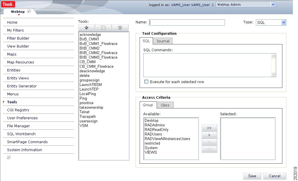
Step 6 ![]() Enter a name for the tool, for example, LAUNCH_CMM.
Enter a name for the tool, for example, LAUNCH_CMM.
Step 7 ![]() From the drop-down list in the Type field, choose CGI/URL.
From the drop-down list in the Type field, choose CGI/URL.
The URL field displays the following:
$(SERVER)/cgi-bin/
Step 8 ![]() To add the name of the CMM launch script to the URL, enter launch_cmm.cgi into the URL, which should now read:
To add the name of the CMM launch script to the URL, enter launch_cmm.cgi into the URL, which should now read:
$(SERVER)/cgi-bin/launch_cmm.cgi
Step 9 ![]() Move all of the available Access Criteria items from the Available list to the Selected list as shown in Figure 5-20.
Move all of the available Access Criteria items from the Available list to the Selected list as shown in Figure 5-20.
Figure 5-20 Editing the LAUNCH_CMM Tool
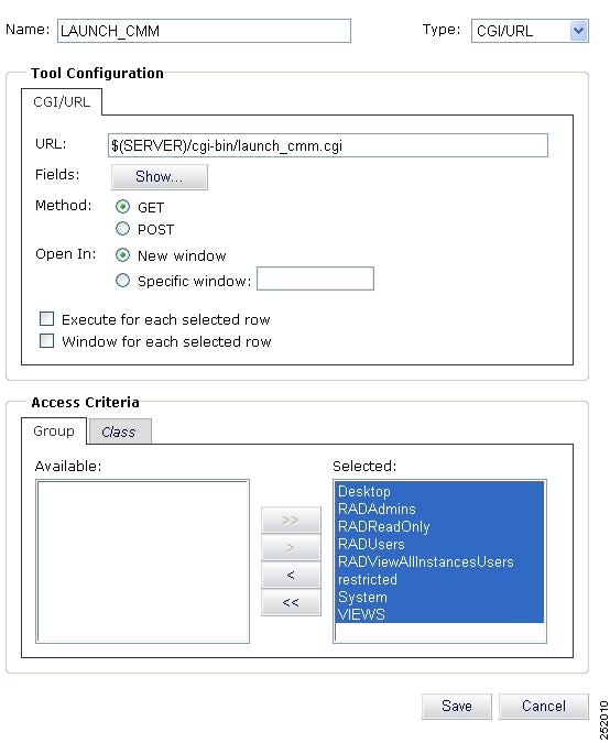
Step 10 ![]() Click the Class tab.
Click the Class tab.
Step 11 ![]() Move all of the available Class items from the Available list to the Selected list.
Move all of the available Class items from the Available list to the Selected list.
Step 12 ![]() Click the Save button.
Click the Save button.
Step 13 ![]() Complete these steps to add the Launch CMM Flowtrace tool.
Complete these steps to add the Launch CMM Flowtrace tool.
a. ![]() On the Webtop Tools page, click the plus sign icon (+).
On the Webtop Tools page, click the plus sign icon (+).
The Webtop Tool Configuration page appears.
b. ![]() Enter the configuration information for the Launch CMM Flowtrace tool as shown in Figure 5-21.
Enter the configuration information for the Launch CMM Flowtrace tool as shown in Figure 5-21.
–![]() In the Name field, enter a name for the tool; for example, LAUNCH_CMM_Flowtrace.
In the Name field, enter a name for the tool; for example, LAUNCH_CMM_Flowtrace.
–![]() From the drop-down list in the Type field, choose CGI/URL.
From the drop-down list in the Type field, choose CGI/URL.
The URL field displays the following:
$(SERVER)/cgi-bin/
–![]() To add the name of the CMM launch script to the URL, enter launch_cmm_flowtrace.cgi into the URL, which should now read:
To add the name of the CMM launch script to the URL, enter launch_cmm_flowtrace.cgi into the URL, which should now read:
$(SERVER)/cgi-bin/launch_cmm_flowtrace.cgi
–![]() Click the Show button to show the available alert fields for the tool.
Click the Show button to show the available alert fields for the tool.
–![]() Move the McastGroup and McastSource items from the list of Available fields to the list of Selected items.
Move the McastGroup and McastSource items from the list of Available fields to the list of Selected items.
–![]() Check the Execute for each selected row and Window for each selected row check boxes.
Check the Execute for each selected row and Window for each selected row check boxes.
Figure 5-21 Configuring the Launch CMM Flowtrace Tool
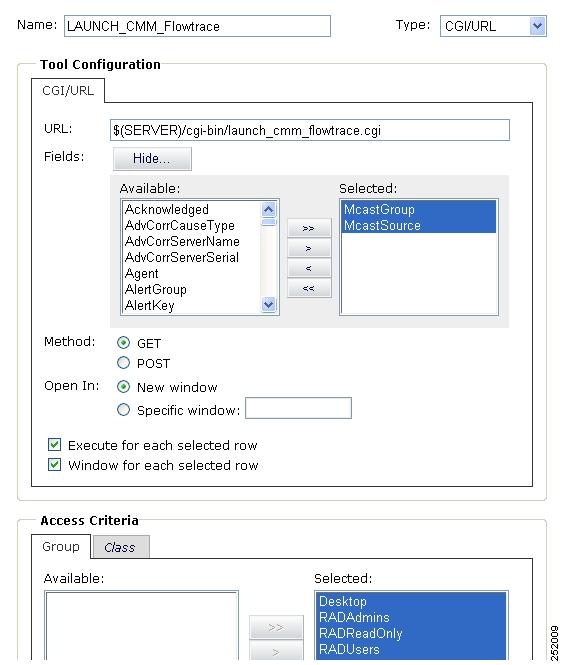
–![]() Move all of the available Group criteria from the Available list to the Selected list.
Move all of the available Group criteria from the Available list to the Selected list.
–![]() Click the Class tab.
Click the Class tab.
–![]() Move all of the available Class criteria from the Available list to the Selected list.
Move all of the available Class criteria from the Available list to the Selected list.
Step 14 ![]() Click the Save button.
Click the Save button.
Registering the CGI Files
Complete these steps to register the CGI files used for the Launch CMM and Launch CMM Flowtrace tools.
Step 1 ![]() On the Webtop main page, click CGI Registry.
On the Webtop main page, click CGI Registry.
The CGI Registration Page appears.
Step 2 ![]() In the list of CGI scripts, highlight the name of the launch_cmm.cgi script and then click the Register button.
In the list of CGI scripts, highlight the name of the launch_cmm.cgi script and then click the Register button.
The Register CGI page appears.
Step 3 ![]() On the Register CGI page, complete these steps, as shown in Figure 5-22:
On the Register CGI page, complete these steps, as shown in Figure 5-22:
Figure 5-22 Registering a CGI Script
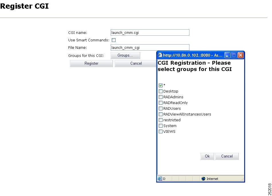
a. ![]() In the CGI name field, enter the name of the CGI script; for example, launch_cmm.cgi.
In the CGI name field, enter the name of the CGI script; for example, launch_cmm.cgi.
b. ![]() In the File Name field, enter the same information.
In the File Name field, enter the same information.
c. ![]() Click the Groups button.
Click the Groups button.
A list of available groups appears.
d. ![]() Check the check box for all groups—this is the check box marked with an asterisk (*).
Check the check box for all groups—this is the check box marked with an asterisk (*).
e. ![]() Click OK.
Click OK.
Step 4 ![]() Repeat Step 2 and Step 3 for the launch_cmm_flowtrace.cgi script.
Repeat Step 2 and Step 3 for the launch_cmm_flowtrace.cgi script.
Creating the CMM Menus
TBSM for VAMS 2.0 contains a preconfigured menu called VAMS that is assigned the label "VAMS Tools." After you have added the VAMS tools and registered the associated CGI scripts, complete these steps to create menus to launch the tools from TBSM, and add these menus to the preconfigured VAMS menu:
Step 1 ![]() On the Webtop start menu, click Menus.
On the Webtop start menu, click Menus.
The Menus Editor page appears.
Step 2 ![]() Click the Create Menu button.
Click the Create Menu button.
The Menu Editor dialog appears.
On the Menu Editor dialog, complete the steps to configure a menu for the VAMS tools, as shown in Figure 5-23.
Figure 5-23 Adding a Menu for the VAMS Tools
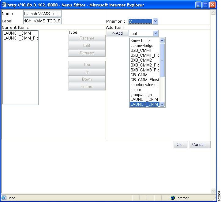
a. ![]() In the Name field, enter a name for the menu; for example, Launch _VAMS_Tools.
In the Name field, enter a name for the menu; for example, Launch _VAMS_Tools.
Note ![]() The menu name cannot contain spaces.
The menu name cannot contain spaces.
b. ![]() In the Label field, enter a label for the menu.
In the Label field, enter a label for the menu.
c. ![]() If you want to specify a mnemonic for the menu, select one from the drop-down list in the Mnemonic field.
If you want to specify a mnemonic for the menu, select one from the drop-down list in the Mnemonic field.
d. ![]() From the drop-down list in the Add Item field, choose tool.
From the drop-down list in the Add Item field, choose tool.
e. ![]() From the list of tools, select the LAUNCH_CMM tool and then click Add.
From the list of tools, select the LAUNCH_CMM tool and then click Add.
f. ![]() Select the LAUNCH_CMM_Flowtrace tool and then click Add
Select the LAUNCH_CMM_Flowtrace tool and then click Add
g. ![]() Click OK.
Click OK.
The specified menu is added. The Menus Editor page appears.
Step 3 ![]() Complete these steps to add the menu that you just created to the VAMS Tools menu.
Complete these steps to add the menu that you just created to the VAMS Tools menu.
a. ![]() On the Menus Editor page, from the list of menus, select VAMS, and then click the Modify Menu button.
On the Menus Editor page, from the list of menus, select VAMS, and then click the Modify Menu button.
b. ![]() From the drop-down list in the Add Item field, select Menu.
From the drop-down list in the Add Item field, select Menu.
A list of the current menu labels appears.
c. ![]() From the drop-down list of menu labels, select the menu label that you assigned to the Launch CMM Tools menu (LAUNCH_CMM_TOOLS) and then click Add.
From the drop-down list of menu labels, select the menu label that you assigned to the Launch CMM Tools menu (LAUNCH_CMM_TOOLS) and then click Add.
The LAUNCH_CMM_TOOLS label appears in the list of menus associated for the VAMS menu.
d. ![]() Click OK to save the changes to the VAMS menu.
Click OK to save the changes to the VAMS menu.
When an event list is launched from either TBSM or directly from Webtop, VAMS users will now be able to select the VAMS menu and launch the CMM application or the CMM flowtrace feature.
Installing IBM Tivoli Netcool View for ANA
To install IBM Tivoli Netcool View for ANA:
Step 1 ![]() FTP the Cisco ANA AdapterView.elc file from caveat CSCsk84768 to the Netcool server.
FTP the Cisco ANA AdapterView.elc file from caveat CSCsk84768 to the Netcool server.
Step 2 ![]() Put it in the $OMNIHOME/utils directory.
Put it in the $OMNIHOME/utils directory.
Step 3 ![]() Open Netcool View, choose File > Open.
Open Netcool View, choose File > Open.
Step 4 ![]() Browse and select the $OMNIHOME/utils/Cisco ANA.elc file.
Browse and select the $OMNIHOME/utils/Cisco ANA.elc file.
 Feedback