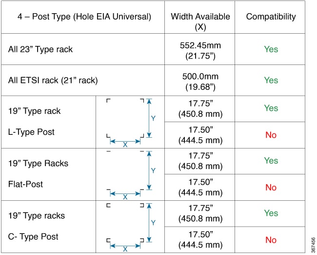
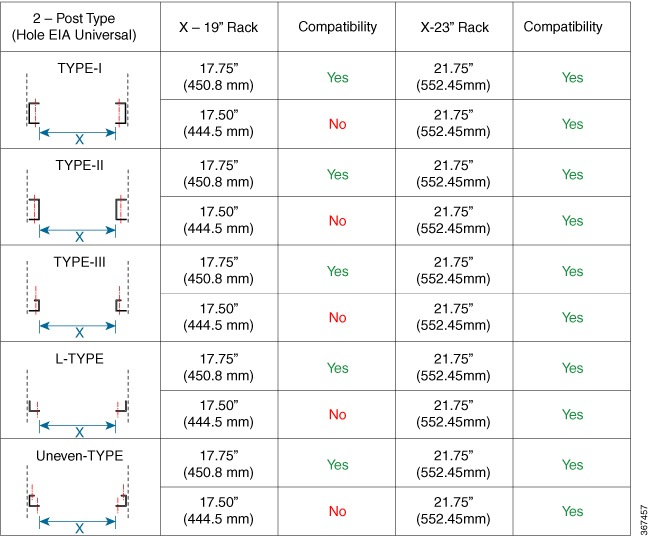
Install the Device

Before you begin this task, ensure that you have read and understood the safety warnings in the Standard Warning Statements section of the Safety Warnings handout topic.

Installing the Cisco NCS 540 involves these tasks:


Note


All the installation instructions for Cisco N540-24Z8Q2C-SYS, N540X-ACC-SYS, N540-ACC-SYS, N540-28Z4C-SYS-A/D, N540-12Z20G-SYS-A/D, N540X-12Z16G-SYS-A/D and N540X-16Z4G8Q2C-A/D variants remains similar and any differences between the routers are specifically called out.

The illustrations are for reference purpose only and may vary based on your Cisco NCS 540 variant.


Rack Compatibility

We recommend that you follow these rack specifications.
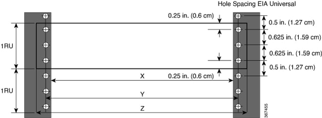
Rack Types

Figure 1. Rack specification EIA (19 inches and 23 inches)
Table 1. Rack specification EIA (19 inches and 23 inches)

Post Type

Rack Type

Rack Front Opening (X)

Rack Mounting Hole Centre-Centre (Y)

Mounting Flange Dimension (Z)

4 Post

19 inches (48.3 centimeters)

17.75 inches (45 centimeters)

18.31 inches (46.5 centimeters)

19 inches (48.2 centimeters)

2 Post

4 Post

23 inches (58.4 centimeters)

21.75 inches (55.24 centimeters)

22.31 inches (56.6 centimeters)

23 inches (58.4 centimeters)

2 Post

Figure 2. Four Post Rack Type
Figure 3. Two Post Rack Type

Set up Device on Rack or Wall

You can choose to either set up the Cisco NCS 540 on a rack or wall mount it.


Note


Wall mount is supported only on Cisco N540-24Z8Q2C-SYS, N540X-ACC-SYS, N540-ACC-SYS, N540-28Z4C-SYS-A/D, and N540-12Z20G-SYS-A/D routers.


Rack-Mount

The device is shipped with rack mounting brackets that are to be secured on the sides of the device.


Caution


If the rack is on wheels, ensure that the brakes are engaged or the rack is otherwise stabilized.
Table 2. Cisco NCS 540 Router Rack-Mount Kit

Quantity

Part Description

2

Rack-mount brackets

8

M4 x 0.7 x 6-mm Phillips flat-head screws

31

M3 x 0.5 x 4-mm Phillips countersink screws

1 Top cover or the NEBs kit is an optional accessory to improve the airflow, hence it may not be a part of your standard package.

Note


The device is shipped with the new cable management brackets. If you require the old long cable management brackets, you need to order A920-CBL-BRKT-H.


Table 3. N540X-16Z4G8Q2C A/D Router Rack-Mount Kit

Quantity

Part Description

2

Rack-mount brackets

8

M3 x 0.5 x 6-mm Phillips flat-head screws

Procedure


Step 1

(Optional) Attach the top cover or the NEBs kit by using the M3 screws to the chassis.

Step 2

Attach the rack-mount brackets and the cable guides to the router as follows:

  1. The router has port-side intake modules, position the router so that its ports are facing the cold aisle.

  2. Position the bracket ears facing front or middle rack-mount, on the side of the chassis so that the holes are aligned.

  3. Use four M4 screws to attach the brackets to the chassis.

  4. Repeat Steps 1b and 1c with the other rack-mount bracket on the other side of the router.

    Figure 4. Installing Rack-Mount Brackets

    1

    Top cover or the NEBs kit

    2

    Rack-mount brackets

    3

    Power supply unit

    -

    -

    Figure 5. Installing Cable Management and 19 inch Rack-Mount Brackets in the Front
    Figure 6. Installing Cable Management and 19 inch Rack-Mount Brackets in the Middle
    Figure 7. Installing 19 inch Rack-Mount Brackets in the Middle (N540X-16Z4G8Q2C-A/D)
    Table 4. Requirement for installing rack-mount brackets in the middle

    Serial No

    Part Number

    Quantity

    1

    700-118409-01

    2

    2

    48-1363-01

    8

    Figure 8. N540X-16Z4G8Q2C-A/D chassis with 19 inch rack-mount brackets mounted at the middle with cable management brackets in the front
    Table 5. Requirement for installing rack-mount brackets in the middle with cable management brackets in the front

    Serial No

    Part Number

    Quantity

    1

    700-119475-02

    2

    2

    48-1363-01

    4

    3

    700-05613-01

    2

    4

    48-0654-01

    2

    Figure 9. N540X-16Z4G8Q2C-A/D chassis with 19 inch rack-mount angle mounted at the middle installed on two post 19 inch rack
    Table 6. Requirement for installing rack-mount brackets in the middle of a two post 19 inch rack

    Serial No

    Part Number

    Quantity

    1

    48-101690-01

    4

    Figure 10. N540X-16Z4G8Q2C-A/D chassis with 19 inch rack-mount angle mounted at the front
    Table 7. Requirement for installing rack-mount brackets in the front

    Serial No

    Part Number

    Quantity

    1

    700-118409-01

    2

    2

    48-1363-01

    8

    Figure 11. N540X-16Z4G8Q2C-A/D chassis with 19 inch rack-mount angle mounted at the front installed on two post 19 inch rack
    Table 8. Requirement for installing rack-mount angle mounted at the front installed on two post 19 inch rack mount brackets

    Serial No

    Part Number

    Quantity

    1

    48-101690-01

    4

    Figure 12. N540X-16Z4G8Q2C-A/D chassis with 19 inch rack-mount brackets mounted at the front with cable management bracket at the front
    Table 9. Requirement for installing rack-mount brackets mounted at the front with cable management bracket at the front

    Serial No

    Part Number

    Quantity

    1

    700-05613-01

    2

    2

    48-0654-01

    2

    Figure 13. Installing Cable Management and 23 inch Rack-Mount Brackets in the Front
    Figure 14. Installing Cable Management and 23 inch Rack-Mount Brackets in the Middle
    Figure 15. Installing Cable Management and ETSI Rack-Mount Brackets in the Middle

Step 3

Install the router onto the 2-post rack as follows:

  1. Lift and position the router into position between the two rack posts.

  2. Move the router until the rack-mount brackets come in contact with the two rack posts.

  3. Hold the chassis at level and have another while the second person insert two screws (12-24 or 10-32, depending on the rack type) in each of the two rack-mount brackets (using a total of four screws) and into the cage nuts or threaded holes in the vertical rack-mounting rails.

  4. Tighten the 10-32 screws to 20 in-lb (2.26 N.m) or tighten the 12-24 screws to 30 in-lb (3.39 N.m).


Wall Mount

Install the wall mounting brackets and cable guides on to the chassis before you mount the chassis on the wall.


Note


The wall mount is supported only on Cisco N540-24Z8Q2C-SYS, N540X-ACC-SYS, N540-ACC-SYS, N540-28Z4C-SYS-A/D, and N540-12Z20G-SYS-A/D routers.


Install Wall Brackets

The device is shipped with wall mounting brackets that are to be secured on the sides of the device.

Procedure

Step 1

Remove the wall mounting brackets from the accessory kit and position them beside the device.

Note

 
You can install the brackets as shown in the figure.
Figure 16. Install Wall Mount Brackets (N540-28Z4C-SYS-D)

Step 2

Secure the bracket to the device with the recommended maximum torque of 10 inch-pounds (1.1 newton meters).


Wall Mount the Device


Note


While you mount the device, always ensure that the power supplies are at the top position.

For the support of the device and cables, ensure that the device is attached securely to wall studs or to a firmly attached plywood mounting backboard.

Figure 17. Wall Mount the Device (N540-28Z4C-SYS-D)

Caution


Before mounting the device, ensure that all unused holes at the sides of the device are always protected by screws.


Installing the Air Filter

This section describes installing the air filter, N540X-16Z4G8Q2C-F, on the following NCS 540 router variants:

  • N540X-16Z4G8Q2C-A

  • N540X-16Z4G8Q2C-D


Note


The maximum operating temperature is 60°C when air filters and dust covers are installed on the system.

The maximum operating temperature increases to 70°C when air filters and dust covers are removed from the system.


Note


The air filters are for one-time use only. In general, we recommend that you inspect the air filter every three months and replace it every six months if needed.


Before you begin

  • Complete the "Rack-Mount" procedure.

  • Since the air filter is installed from the top, make sure that there is approximately 2 rack units of space above the router.

Procedure


Step 1

Position the air filter on top of the air inlet side of the chassis as shown in the figure.

Figure 18. Position the air filter

Note


Locate the label "TOP REAR" on the air filter's top bracket. The label serves as an installation guide indicating that this side of the air filter should be positioned at the top of the router chassis.

Step 2

From the top, slide the air filter to cover the air vents as shown in the figure.

Figure 19. Slide the air filter

Note


There are three magnetic points on the air filter as shown in the figure. The magnetic points keep the air filter secured to the router chassis.

Figure 20. Magnetic points

Install the air filter (N540-FR-KIT-EG) (front and side views)

This section describes installing the air filter, N540-FR-KIT-EG, on the following NCS 540 router variants:

  • N540X-16Z4G8Q2C-A

  • N540X-16Z4G8Q2C-D


Note


The air filters are for one-time use only. In general, we recommend that you inspect the air filter every three months and replace it every six months if needed.


Before you begin

  • Complete the "Rack-Mount" procedure.

  • Since the air filter is installed from the top, make sure that there is approximately 2 rack units of space above the router.

Procedure


Step 1

Mount the cable management onto the mounting ears on both sides.

Figure 21. Mount the cable management
Part Part Number Quantity

1 - Cable management

800-52079-01

2

Note


Use thumb screw to fix cable management with rack mount bracket.

Step 2

Assemble the front air filter cover.

Figure 22. Front air filter
Part Part Number Quantity

1 - Cable management

800-52079-01

2

2 - Air filter front cover

700-137145-01

1

Step 3

Fix the side-mounted air filter onto the air baffle (RH).

Figure 23. Side-mounted air filter

Part Part Number Quantity

1 - Air filter

800-112483-02

1

2 - Air baffle

700-137173-01

1

Figure 24. Air filter
Part Part Number Quantity

1 - Air baffle - Right side with air filter

700-137173-01

800-112483-02

1

2 - Air baffle left side

700-137549-01

1

Warning


Air filter baffle with air filter should be assembled in right side of the chassis air inlet.

Step 4

Mount both the right and left air baffles on the chassis.

Figure 25. Mounting air filters on both sides of chassis
Part Part Number Quantity

Exhaust Baffle - 1

700-137549-01

1

Right side air baffle with filter - 2

700-137173-01

800-112483-02

1

Warning


We recommend that you use only the screws with part number 48-101690-01 to mount the chassis on rack. Other screws are not recommended for the side filter assembly.

Warning


The ports without optics should be closed with dust caps.


Install the air filter (N540-FR-KT-EG-200) (front and side views)

This section describes installing the air filter, N540-FR-KT-EG-200, on the following NCS 540 router variants:

  • N540X-16Z4G8Q2C-A

  • N540X-16Z4G8Q2C-D


Note


The air filters are for one-time use only. In general, we recommend that you inspect the air filter every three months and replace it every six months if needed.


Before you begin

  • Complete the "Rack-Mount" procedure.

  • Since the air filter is installed from the top, make sure that there is approximately 2 rack units of space above the router.

Procedure


Step 1

Fix mounting ears on both sides of the chassis and fasten with screws.

Figure 26. Fix mounting ears on chassis
Part Part Number Quantity

1

700-138377-01

2

2

48-1363-1

8

Step 2

Mount N540X-16Z4G8Q2C-A/D chassis with 19-inch rack-mount angle at the front on two post 19-inch rack.

Figure 27. N540X-16Z4G8Q2C-A/D chassis with 19-inch rack-mount angle mounted at the front installed on two post 19-inch rack

Requirement for installing rack-mount angle mounted at the front installed on two post 19-inch rack mount brackets

Part Part Number Quantity

1

48-101690-01

4

Step 3

Assemble the air filter on the vent area of air filter tray.

Figure 28. Air filter with tray
Part Part Number Quantity

1 - Air tray

800-52147-01

1

2 - Air filter

800-52113-01

1

Step 4

Mount the air filter on the rackmount guide and tighten with captive screw on the tray.

Figure 29. Mounting air filters on rack and both sides of chassis
Part Part Number Quantity

1 - Air tray

800-52147-01

1

Step 5

Mount the air filter cover on top of the tray and fasten with captive screw after fixing all the optics.

Figure 30. Air filter cover mounter on air filter tray
Part Part Number Quantity

1 - Air filter cover

700-138383-01

1

Figure 31. Air filter installed on chassis

Warning


We recommend that you use only the screws with part number 48-101690-01 to mount the chassis on rack. Other screws are not recommended for the side filter assembly.

Warning


The ports without optics should be closed with dust caps.


Ground the Device

Before you begin this task, ensure that you have read and understood the safety warnings in the Preventing ESD Damage section of the Safety Warnings handout topic.

Before you connect the power or turn on the power to the device, you must provide an adequate device ground (earth) connection to your device.

This section describes how to ground the device. The grounding lug location is on the back panel of the device.

Procedure


Step 1

Verify that the ground cable is connected to the top of the rack and according to local site practice.

Figure 32. Ground Lug

Step 2

Attach one end of the shelf ground cable (#6 AWG cable) to the ground point on the rear of the chassis using the specified dual-hole lug connector.

  1. Use a wire-stripping tool to remove approximately 0.75 inches (19 mm) of the covering from the end of the grounding cable.

  2. Insert the stripped end of the grounding cable into the open end of the grounding lug.

  3. Use the crimping tool to secure the grounding cable in the grounding lug.

  4. Remove the adhesive label from the grounding pad on the chassis.

  5. Place the grounding lug against the grounding pad so that there is solid metal-to-metal contact, and insert the two M4 screws with washers through the holes in the grounding lug and into the grounding pad.

  6. Ensure that the lug and cable do not interfere with other equipment.

  7. Prepare the other end of the grounding cable and connect it to an appropriate grounding point in your site to ensure adequate earth ground.


Install the AC Power Cables

To install the AC power cables in the power supply slots:

Procedure


Step 1

Plug the power supply cord in the power supply module.

Step 2

Insert the power supply cord into the tie [1,3] and tighten the tie around the power supply cord as shown in [2,4] in the figure below.

Figure 33. Attach the AC Power Tie-and-Clip Cord

Note

 
These images are for only representation purposes. Certain variants of Cisco NCS 540 do not include a tie for the power supply cord.

Activate an AC Power Supply Module

Perform the following procedure to activate an AC power supply:

Procedure


Step 1

Plug the power cord into the power supply.

Step 2

Connect the other end of the power cord to an AC-input power source.

Step 3

Verify power supply operation by checking if the respective power supply front panel LED (PM0 or PM1) is green.

Step 4

If the LEDs indicate a power problem, see Troubleshooting for troubleshooting information.

Step 5

If you are also connecting a redundant AC power supply, repeat these steps for the second power source.

Note

 
If you are connecting a redundant AC power supply, ensure that each power supply is connected to a separate power source in order to prevent power loss in the event of a power failure.

Install the DC Power Cables


Note


When installing DC power supply, use 12AWG, 90°C temperature rated cable. The recommended cable length is 3 meters maximum from source. Up to 5 meters use 10AWG, and up to 3 meters use 12AWG, 90°C temperature rated cable and for other length contact Cisco.


Note


For N540X-16Z4G8Q2C-A/D and N540X-16Z8Q2C-D, when installing DC power supply, use 14-16AWG, 90°C temperature rated cable. The recommended cable length is 3 meters maximum from source. Up to 5 meters use 14AWG, and up to 3 meters use 16AWG, 90°C temperature rated cable and for other length contact Cisco.


Note


  • Always ensure that the building’s installation for short-circuit (overcurrent) protection does not exceed 15A.

  • We recommended using a Circuit breaker or a fast acting fuse with a maximum DC rating of 10A for over current protection.


Note


The DC connector or terminal block has an in built screw and cage nut to which torque of 1.3 to 1.8 N-m can be applied.
Figure 34. DC Connector with In built Screw

A

0.74 in. (1.88 cm)

C

0.18 in. (0.46 cm)

B

0.25 in. (0.64 cm)

D

0.14 in. (0.36 cm)

M

0.62 in. (1.58 cm)

To attach the DC power supplies:

Procedure


Step 1

Locate the terminal block plug.

Step 2

Insert the DC-input power source wires into the terminal block plug.

Step 3

Attach the DC supply wires using the designated screws.

Step 4

Use a ratcheting torque screwdriver to torque the terminal block plug captive screw. See the following figure.

Figure 35. Attach the DC Power Supply Wires

Note

 
These images are for only representation purposes. Certain variants of Cisco NCS 540 may vary.

Activate a DC Power Supply Module

Perform the following procedure to activate a DC power supply:

Procedure


Step 1

Remove the tape from the circuit-breaker router handle, and restore power by moving the circuit-breaker router handle to the On (|) position.

Step 2

Verify the power supply operation by checking whether the respective power supply front panel LED (PM0 or PM1) is green.

Step 3

If the LEDs indicate any issues with power problem, see Troubleshooting.

Step 4

If you are also connecting a redundant DC power supply, repeat these steps for the second power source.

Note

 
If you are connecting a redundant DC power supply, ensure that each power supply is connected to a separate power source in order to prevent power loss in the event of a power failure.

Port Connection Guidelines

Depending on the chassis, you can use Quad Small Form-Factor Pluggable Plus (QSFP+), QSFP28, SFP, SFP+, and RJ45 connectors to connect the ports on the line cards to other network devices.

To prevent damage to the fiber-optic cables, we recommend that you keep the transceivers disconnected from their fiber-optic cables when installing the transceiver in the line card. Before removing a transceiver from the router, remove the cable from the transceiver.

To maximize the effectiveness and life of your transceivers and optical cables, do the following:

  • Wear an ESD-preventative wrist strap that is connected to an earth ground whenever handling transceivers. The router is typically grounded during installation and provides an ESD port to which you can connect your wrist strap.

  • Do not remove and insert a transceiver more often than is necessary. Repeated removals and insertions can shorten its useful life.

  • Keep the transceivers and fiber-optic cables clean and dust free to maintain high signal accuracy and to prevent damage to the connectors. Attenuation (loss of light) is increased by contamination and should be kept below 0.35 dB.

    • Clean these parts before installation to prevent dust from scratching the fiber-optic cable ends.

    • Clean the connectors regularly; the required frequency for cleaning depends upon the environment. In addition, clean connectors when they are exposed to dust or accidentally touched. Both wet and dry cleaning techniques can be effective; refer to your site's fiber-optic connection cleaning procedures.

    • Do not touch the ends of connectors. Touching the ends can leave fingerprints and cause other contamination.

  • Inspect routinely for dust and damage. If you suspect damage, clean and then inspect fiber ends under a microscope to determine if damage has occurred.

Connect to the Console Port

Before you create a network management connection for the router or connect the router to the network, you must create a local management connection through a console terminal and configure an IP address for the router. You also can use the console to perform the following functions (each of which can be performed through the management interface after you make that connection):

  • Configure the router using the command-line interface (CLI).

  • Monitor network statistics and errors.

  • Configure Simple Network Management Protocol (SNMP) agent parameters.

  • Download software updates.

The system console port is an RJ-45 receptacle for connecting a data terminal to perform the initial configuration of Cisco NCS 540 fixed-port chassis. The console cable is shipped with the hardware.


Note


Only RJ45 to DB-9 adapter cable is provided in the package.

Caution


We recommend you to set the terminal to these operational values: 115200 bps, 8 data bits, no parity, 2 stop bits and flow control as none. Setting any flow control, may cause congestion in the console buffer leading to unexpected behavior.


Figure 36. Connecting the USB Console Cable to the Chassis

1

RJ45 Port

2

USB Type-A console cable

Follow this procedure to connect a data terminal to the console port.

Before you begin

  • The router must be fully installed in its rack, connected to a power source, and grounded.

  • The necessary cabling for the console, management, and network connections must be available.

    • An RJ-45 rollover cable and DB9F/RJ-45 adapter are provided in the router accessory kit.

    • Network cabling should already be routed to the location of the installed router.

Procedure


Step 1

Set your terminal to these operational values: 115200 bps, 8 data bits, no parity, and 2 stop bits and flow control as none. Setting any flow control, may cause congestion in the console buffer leading to unexpected behavior.

Step 2

Attach the terminal end of the cable to the interface port on the data terminal.

Step 3

Attach the other end of the cable to the console port.


Following table represents the RJ-45 cable pin-out information.

Table 10. RJ-45 Straight-through Cable Pin-outs

RJ-45 Pin

Signal

1

2

3

Tx

4

Ground (GND)

5

GND

6

Rx

7

8

Connect to the Management Ethernet Port

The management Ethernet port provides out-of-band management, which enables you to use the command-line interface (CLI) to manage the router by its IP address. This port uses a 10/100/1000 Ethernet connection with an RJ-45 interface.


Note


To prevent an IP address conflict, do not connect the management Ethernet port until the initial configuration is complete.

To connect cables to the system management port, attach Category 5 cables directly to the RJ-45 receptacle on the management Ethernet port.

Figure 37. Console Port

Note


To comply with GR-1089-CORE, the intra-building port(s) of the equipment must use shielded intra-building cabling or wiring that is grounded at both ends.

Before you begin

You must complete initial router configuration.

Procedure


Step 1

Plug the cable directly into the RJ-45 receptacle.

Step 2

Connect the network end of your RJ-45 cable to a switch, hub, repeater, or other external equipment.


Connecting Timing Cables


Note


When installing the cables to the RSPs, we recommend that you leave a service loop of extra cable to enable fan tray removal.

The following sections describe how to connect timing cables to the router:

Connecting a Cable to the BITS Interface

The following steps describe how to connect a cable to the router’s BITS port:

Procedure


Step 1

Confirm that the router is powered off.

Step 2

Connect one end of the cable to the BITS port using a straight-through, shielded RJ48C-to-RJ48C cable.

Step 3

Connect the other end to the BTS patch or demarcation panel at your site.

Step 4

Turn on the power to the router.

Note

 
The use of two BITS sources or a Y-cable is optional. Each BITS input port is routed to both the RSPs, so that the SETS device on each RSP has visibility to both the BITS inputs.

Warning


To comply with the Telcordia GR-1089 NEBS standard for electromagnetic compatibility and safety, connect the BITS ports only to intra-building or unexposed wiring or cable. The intrabuilding cable must be shielded and the shield must be grounded at both ends. The intra-building port(s) of the equipment or subassembly must not be metallically connected to interfaces that connect to the OSP or its wiring. These interfaces are designed for use only as intra-building interfaces (Type 2 or Type 4 ports as described in GR-1089-CORE) and require isolation from the exposed OSP cabling. The addition of Primary Protectors is not sufficient protection in order to connect these interfaces metallically to OSP wiring.


Connecting Cables to a GPS Interface

The following sections describe how to connect cables from the router to a GPS unit for input or output timing of frequency:

Connecting a Cable to the Input 10MHz or 1PPS Interface

Procedure

Step 1

Connect one end of a mini-coax cable to the GPS unit.

Step 2

Connect the other end of the mini-coax cable to the 10MHz or 1PPS port on the RSP of the router.


Connecting a Cable to the Output 10MHz or 1PPS Interface

Procedure

Step 1

Connect one end of a mini-coax cable to the Slave unit.

Step 2

Connect the other end of the mini-coax cable to the 10MHz or 1PPS port of the router.


Connecting a Cable to the ToD Interface

Procedure

Step 1

Connect one end of a straight-through Ethernet cable to the GPS unit.

Step 2

Connect the other end of the straight-through Ethernet cable to the ToD or 1-PPS port on the RSP of the router.

Warning


To comply with the Telcordia GR-1089 NEBS standard for electromagnetic compatibility and safety, connect the ToD ports only to intra-building or unexposed wiring or cable. The intrabuilding cable must be shielded and the shield must be grounded at both ends. The intra-building port(s) of the equipment or subassembly must not be metallically connected to interfaces that connect to the OSP or its wiring. These interfaces are designed for use as intra-building interfaces only (Type 2 or Type 4 ports as described in GR-1089-CORE) and require isolation from the exposed OSP cabling. The addition of Primary Protectors is not sufficient protection in order to connect these interfaces metallically to OSP wiring.

Note

 
For more information about GPS-port pinouts, see Pinouts table.

Connecting a Cable to the GNSS Antenna Interface


Note


The GNSS module is not hot swappable.
  1. Connect one end of a shielded coaxial cable to the GNSS RF IN port.

  2. SMA Matting cable assembly Torque should be maintained within 3 in-lb. For Cisco N540-24Z8Q2C-SYS, Cisco N540X-ACC-SYS, and Cisco N540-ACC-SYS nut and washer may be removed when you use a slightly longer mating SMA connector to ensure contact with the connector.

  3. Connect the other end of the shielded coaxial cable to the GNSS antenna. Use a passive splitter if more than one GNSS modules are fed from a single antenna.

Install and Remove Transceiver Modules

Install and Remove SFP Modules

Before you remove or install an SFP or SFP+ module, read the installation information in this section.


Warning


Statement 1051—Laser Radiation

Invisible laser radiation may be emitted from disconnected fibers or connectors. Do not stare into beams or view directly with optical instruments.


Caution


Protect the line card by inserting a clean SFP/SFP+ module cage cover, shown in the figure below, into the optical module cage when there is no SFP or SFP+ module installed.
Figure 38. SFP/SFP+ Module Cage Cover

Caution


Protect the SFP or SFP+ modules by inserting clean dust covers into them after the cables are removed. Be sure to clean the optic surfaces of the fiber cables before you plug them back into the optical ports of another module. Avoid getting dust and other contaminants into the optical ports of your SFP or SFP+ modules, because the optics do not work correctly when obstructed by dust.

Caution


We strongly recommended that you do not install or remove the SFP or SFP+ module with fiber-optic cables attached to it because of the potential of damaging the cable, the cable connector, or the optical interfaces in the module. Disconnect all cables before removing or installing an SFP or SFP+ module. Removing and inserting a module can shorten its useful life, so you should not remove and insert modules any more than is absolutely necessary.

Note


When installing an SFP or SFP+ module, you should hear a click as the triangular pin on the bottom of the module snaps into the hole in the receptacle. The click indicates that the module is correctly seated and secured in the receptacle. Verify that the modules are completely seated and secured in their assigned receptacles on the line card by firmly pushing on each SFP or SFP+ module.

Bale Clasp SFP or SFP+ Module

The bale clasp SFP or SFP+ module has a clasp that you use to remove or install the module (see the figure below).

Figure 39. Bale Clasp SFP or SFP+ Module

Install a Bale Clasp SFP or SFP+ Module

To install this type of SFP or SFP+ module, follow these steps:

Procedure

Step 1

Attach an ESD-preventive wrist or ankle strap and follow its instructions for use.

Step 2

Close the bale clasp before inserting the SFP module.

Step 3

Line up the SFP module with the port and slide it into the port (see the figure below).

Figure 40. Installing a Bale Clasp SFP Module into a Port

Note

 
When installing an SFP or SFP+ module, you should hear a click as the triangular pin on the bottom of the SFP module snaps into the hole in the receptacle. This click indicates that the module is correctly seated and secured in the receptacle. Verify that the SFP modules are completely seated and secured in their assigned receptacles on the line card by firmly pushing on each SFP module.

Remove a Bale Clasp SFP or SFP+ Module

To remove this type of SFP or SFP+ module, follow these steps:

Procedure

Step 1

Attach an ESD-preventive wrist or ankle strap and follow its instructions for use.

Step 2

Disconnect and remove all interface cables from the ports; note the current connections of the cables to the ports on the line card.

Step 3

Open the bale clasp on the SFP module with your index finger, as shown in the figure below. If the bale clasp is obstructed and you cannot use your index finger to open it, use a small flat-blade screwdriver or other long, narrow instrument to open the bale clasp.

Step 4

Grasp the SFP module between your thumb and index finger and carefully remove it from the port, as shown in the figure below.

Note

 
This action must be performed during your first instance. After all the ports are populated, this may not be possible.
Figure 41. Removing a Bale Clasp SFP or SFP+ Module

Step 5

Place the removed SFP module on an antistatic mat, or immediately place it in a static shielding bag if you plan to return it to the factory.

Step 6

Protect your line card by inserting a clean SFP module cage covers into the optical module cage when there is no SFP module installed.


Install and Remove QSFP Transceiver Modules


Note


In this section, QSFP refers to QSFP+, QSFP28, and QSFP-DD. Refer to the Cisco Optical Transceiver Handling Guide for additional details on optical transceivers.


This section provides the installation, cabling, and removal instructions for the Quad Small Form-Factor Pluggable (QSFP) transceiver modules. The modules are hot-swappable input/output (I/O) devices that connect the system’s module port electrical circuitry with either a copper or a fiber-optic network.

The following figure shows the 400-Gigabit QSFP-DD transceiver module.

Figure 42. 400-Gigabit QSFP-DD Transceiver Module

1

Pull-tab

2

QSFP-DD transceiver body

3

Electrical connection to the module circuitry


Warning


Statement 1079—Hot Surface

This icon is a hot surface warning. To avoid personal injury, do not touch without proper protection.


Overview

The 40-Gigabit (GE) QSFP+ and 100 Gigabit (QSFP28) transceiver module is a hot-swappable, parallel fiber-optical module with 4 independent optical transmit and receive channels. These channels can terminate in another 40-Gigabit QSFP+ transceiver, or the channels can be broken out to 4 separate 10-Gigabit SFP+ transceivers. The QSFP+ transceiver module connects the electrical circuitry of the system with an optical external network.

The following figure shows the 40-Gigabit optical QSFP+ transceiver. The transceiver is used primarily in short reach applications in switches, routers, and data center equipment where it provides higher density than SFP+ modules. The 100-Gigabit optical QSFP28 transceiver is similar to the 40-Gigabit optical QSFP transceiver.

Figure 43. 40-Gigabit QSFP+ Transceiver Module (Optical)

1

40GBASE QSFP+ transceiver body

3

Electrical connection to the module circuitry

2

Bail-clasp latch

Required Tools and Equipment

You need these tools to install the transceiver modules:

  • Wrist strap or other personal grounding device to prevent ESD occurrences.

  • Antistatic mat or antistatic foam to set the transceiver on.

  • Fiber-optic end-face cleaning tools and inspection equipment.

For information on inspecting and cleaning fiber-optic connections, see Maintaining Transceivers and Optical Cables.

Install the 100-Gigabit Transceiver Module

The QSFP+ or QSFP28 transceiver module can have either a bail-clasp latch or a pull-tab latch. Installation procedures for both types of latches are provided.


Caution


The QSFP+ or QSFP28 transceiver module is a static-sensitive device. Always use an ESD wrist strap or similar individual grounding device when handling QSFP+ or QSFP28 transceiver modules or coming into contact with system modules.

To install an QSFP+ or QSFP28 transceiver module, follow these steps:

Procedure

Step 1

Attach an ESD wrist strap to yourself and a properly grounded point on the chassis or the rack.

Step 2

Remove the QSFP+ or QSFP28 transceiver module from its protective packaging.

Step 3

Check the label on the QSFP+ or QSFP28 transceiver module body to verify that you have the correct model for your network.

Step 4

For optical QSFP+ or QSFP28 transceiver modules, remove the optical bore dust plug and set it aside.

Step 5

For QSFP+ or QSFP28 transceiver modules equipped with a pull-tab, hold the transceiver so that the identifier label is on the top.

Step 6

For QSFP+ or QSFP28 transceiver modules equipped with a bail-clasp latch, keep the bail-clasp aligned in a vertical position.

Step 7

Align the QSFP+ or QSFP28 transceiver module in front of the module’s transceiver socket opening and carefully slide the QSFP+ or QSFP28 transceiver into the socket until the transceiver makes contact with the socket electrical connector (see the figure below).

Figure 44. Installing the 100-Gigabit QSFP28 Transceiver Module (Optical Transceiver Equipped with a Bail-Clasp Latch Shown)

Step 8

Press firmly on the front of the QSFP+ or QSFP28 transceiver module with your thumb to fully seat the transceiver in the module’s transceiver socket (see the below figure).

Caution

 
If the latch is not fully engaged, you might accidentally disconnect the QSFP+ or QSFP28 transceiver module.
Figure 45. Seating the 100-Gigabit QSFP28 Transceiver Module (Optical Transceiver Equipped with a Bail-Clasp Latch Shown)

Step 9

For optical QSFP+ or QSFP28 transceiver modules, reinstall the dust plug into the QSFP+ or QSFP28 transceivers optical bore until you are ready to attach the network interface cable. Do not remove the dust plug until you are ready to attach the network interface cable.


Attach the Optical Network Cable

Before you begin

Before you remove the dust plugs and make any optical connections, follow these guidelines:

  • Keep the protective dust plugs installed in the unplugged fiber-optic cable connectors and in the transceiver optical bores until you are ready to make a connection.

  • Inspect and clean the MPO connector end faces just before you make any connections. For complete information on inspecting and cleaning fiber-optic connections, see the Inspection and Cleaning Procedures for Fiber-Optic Connections document.

  • Grasp the MPO connector only by the housing to plug or unplug a fiber-optic cable.


Note


QSFP transceiver modules are keyed to prevent incorrect insertion.

Note


The multiple-fiber push-on (MPO) connectors on the optical QSFP transceivers support network interface cables with either physical contact (PC) or ultra-physical contact (UPC) flat polished face types. The MPO connectors on the optical QSFP transceivers do not support network interface cables with an angle-polished contact (APC) face type.
Procedure

Step 1

Remove the dust plugs from the optical network interface cable MPO connectors. Save the dust plugs for future use.

Step 2

Inspect and clean the MPO connector’s fiber-optic end faces.

Step 3

Remove the dust plugs from the transceiver module optical bores.

Step 4

Immediately attach the network interface cable MPO connectors to the transceiver module (see the figure below).

Figure 46. Cabling a Transceiver Module

Remove the 100-Gigabit QSFP28 Transceiver Module


Caution


The QSFP+ or QSFP28 transceiver module is a static-sensitive device. Always use an ESD wrist strap or similar individual grounding device when handling QSFP+ or QSFP28 transceiver modules or when coming into contact with modules.

To remove a QSFP+ or QSFP28 transceiver module, follow these steps:

Procedure

Step 1

For optical QSFP+ or QSFP28 transceiver modules, disconnect the network interface cable from the QSFP+ or QSFP28 transceiver connector.

Step 2

For QSFP+ or QSFP28 transceiver modules equipped with a bail-clasp latch (see the below figure, top view):

  1. Pivot the bail-clasp down to the horizontal position.

  2. Immediately install the dust plug into the transceivers optical bore.

  3. Grasp the sides of the QSFP+ or QSFP28 transceiver and slide it out of the module socket.

Step 3

For QSFP+ or QSFP28 transceivers equipped with a pull tab latch (see the below figure, bottom view):

  1. Immediately install the dust plug into the transceiver’s optical bore.

  2. Grasp the tab and gently pull to release the transceiver from the socket.

  3. Slide the transceiver out of the socket.

Figure 47. Removing the 100-Gigabit QSFP28 Transceiver Module

Step 4

Place the QSFP+ or QSFP28 transceiver module into an antistatic bag.


Connect Interface Ports

You can connect optical interface ports on with other devices for network connectivity.

Connect a Fiber-Optic Port to the Network

Depending on the model that you are using, you can use either QSFP+ or QSFP28 transceivers. Some transceivers work with fiber-optic cables that you attach to the transceivers and other transceivers work with pre-attached copper cables. When installing fiber-optic cables for a port, you must install SFP transceivers for 1-Gigabit optical ports or install SFP+ transceivers for 10-Gigabit optical ports or QSFP+ transceivers for 100-Gigabit ports before installing the fiber-optic cable in the transceivers.


Caution


Removing and installing a transceiver can shorten its useful life. Do not remove and insert transceivers more than it is absolutely necessary. We recommended that you disconnect cables before installing or removing transceivers to prevent damage to the cable or transceiver.


Disconnect Optical Ports from the Network

When you need to remove fiber-optic transceivers, you must first remove the fiber-optic cables from the transceiver before you remove the transceiver from the port.

Maintain Transceivers and Optical Cables

To maintain high signal accuracy and to prevent damage to the connectors, transceivers and fiber-optic cables must be kept clean and free of dust. Attenuation (loss of light) is increased by contamination and should be below 0.35 dB.

Consider the following maintenance guidelines:

  • Transceivers are static sensitive. To prevent ESD damage, wear an ESD-preventative wrist strap that is connected to the grounded chassis.

  • Do not remove and insert a transceiver more than it is necessary. Repeated removals and insertions can shorten its useful life.

  • Keep all optical connections covered when not in use. Clean them before use to prevent dust from scratching the fiber-optic cable ends.

  • Do not touch the ends of connectors. Touching the ends would leave fingerprints and cause other contamination.

  • Clean the connectors regularly; the required frequency of cleaning depends upon the environment. In addition, clean connectors if they are exposed to dust or have been accidentally touched. Both wet and dry cleaning techniques can be effective; refer to your site's fiber-optic connection cleaning procedures.

  • Inspect routinely for dust and damage. Clean and then inspect fiber ends under a microscope to determine whether any damage has occurred.