Cisco NCS 540 Router Overview

The Cisco NCS 540 1RU router complements Cisco’s offerings for IP RAN solutions for the GSM, UMTS, LTE, and CDMA.

The Cisco NCS 540 includes the following variants.

Table 1. Cisco NCS 540 Variants

Variant

Conformal Coating

N540-24Z8Q2C-SYS

No

N540X-ACC-SYS

Yes1

N540-ACC-SYS

No

N540-28Z4C-SYS-A

N540-28Z4C-SYS-D

No

N540-12Z20G-SYS-A

N540-12Z20G-SYS-D

No

N540X-12Z16G-SYS-A

N540X-12Z16G-SYS-D

Yes

N540X-16Z4G8Q2C-A

N540X-16Z4G8Q2C-D

Yes

1 The printed circuit boards are conformal coated to provide enhanced protection against moisture, dust and corrosive gas. For additional information and deployment conditions, we recommend you to contact our Cisco support team.

Note


The Cisco N540-24Z8Q2C-SYS, N540X-ACC-SYS, N540-ACC-SYS, N540-28Z4C-SYS-A/D, N540-12Z20G-SYS-A/D, N540X-12Z16G-SYS-A/D and N540X-16Z4G8Q2C-A/D are collectively referred to as the Cisco NCS 540 Router in this document. Any differences between the routers are specifically called out.


For more information on its features and benefits, see the Cisco Network Convergence System 540 Router Data Sheet.

Network Interfaces

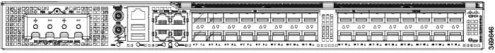
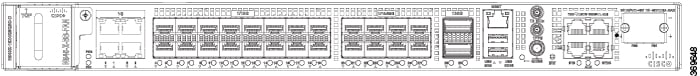
The Cisco NCS 540 1RU Router has the following hardware features:

  • 24 x 10G SFP+ Ports

    • Support DWDM & ZR Optics

  • 8 x 25G SFP+ Ports

  • 2 x 100G QSFP28 Ports
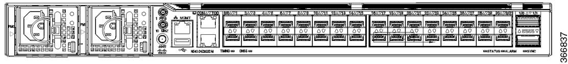
Figure 1. Cisco N540-ACC-SYS

Note


All ports are color coded in the chassis for ease of access; for example, the 10G SFP+ Ports are in pink, the 25G SFP+ Ports are in yellow, and the 100G QSFP28 Ports are in green.
 

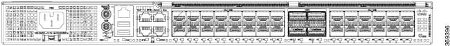
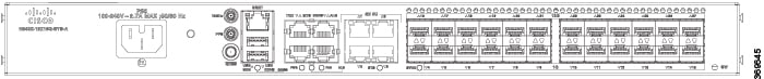
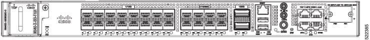
The Cisco N540-28Z4C-SYS-A/D 1RU Router has the following hardware features:

  • 28 x 1G/10G SFP+ Ports

  • 4 x 100G QSFP28 Ports with Non MACsec

Figure 2. Cisco N540-28Z4C-SYS-A
Figure 3. Cisco N540-28Z4C-SYS-D
 

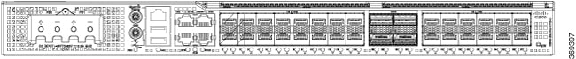
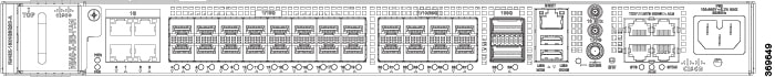
The Cisco N540-12Z20G-SYS-A/D 1RU Router has the following hardware features:

  • 20 x 1G SFP+ Ports

  • 12 x 1G/10G SFP+ Ports

Figure 4. Cisco N540-12Z20G-SYS-A
Figure 5. Cisco N540-12Z20G-SYS-D
 

The Cisco N540X-12Z16G-SYS-A/D 1RU Router has the following hardware features:

  • 12 x 1G SFP+ Ports

  • 12 x 10G/1G SFP+ Ports

  • 4 x 1G Copper Ports

Figure 6. Cisco N540X-12Z16G-SYS-A
Figure 7. Cisco N540X-12Z16G-SYS-D
 

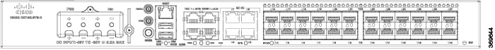
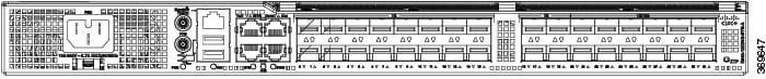
The Cisco N540X-16Z4G8Q2C-A/D 1RU Router has the following hardware features:

  • 4 x 1G Copper Ports

  • 16 x 1G/10G SFP+ Ports

  • 8 x 10G/25G SFP+ Ports

  • 2 x 100G QSFP Ports

Figure 8. Cisco N540X-16Z4G8Q2C-A
Figure 9. Cisco N540X-16Z4G8Q2C-D
The Cisco N540X-16Z8Q2C-D router has the copper ports (0 to 3) removed. The router has the following hardware features:
  • 16 x 1G/10G SFP+ Ports

  • 8 x 10G/25G SFP+ Ports

  • 2 x 100G QSFP Ports

Figure 10. Cisco N540X-16Z8Q2C-D

Interface Naming

The following table shows the interface naming of the Cisco N540-24Z8Q2C-SYS, N540X-ACC-SYS, and N540-ACC-SYS variants:

Table 2. Port Numbering

1G/10G Dual rate ports (SFP+)

1G/10G/25G Dual rate ports (SFP28)

40G/100G ports (QSFP28)

0/0

to

22

24

to

30

1/0

1

23

25

0/31

1/1

The interface-path-id is rack/ slot/ module/ port. The slash between values is required as part of the notation.

  • GigE — 0/0/0/0 - 0/0/0/31

  • TenGigE — 0/0/0/0 - 0/0/0/31

  • TwentyFiveGigE — 0/0/0/24 - 0/0/0/31

  • FortyGigE — 0/0/1/0 - 0/0/1/1

  • HundredGigE — 0/0/1/0 - 0/0/1/1


Note


Dual-Rate functionality is supported only with the Supported SFP.
Table 3. Maximum Number of Inerfaces

Category

Maximum Interface

Port Number

100ME copper

24

0/0 - 23

1GE

32

0/0 - 31

10GE

32 / 40*2

0/0 - 31, 1/0 - 1*

25GE

8 / 16*

0/24 - 31, 1/0 - 1*

40GE

2

1/0 - 1

100GE

2

1/0 - 1

2 *4x10GE or 4x25GE option

The following table shows the interface naming of the Cisco N540-28Z4C-SYS-A/D, N540-12Z20G-SYS-A/D, N540X-12Z16G-SYS-A/D, N540X-16Z4G8Q2C-A/D, and N540X-16Z8Q2C-D variants:

Table 4. Port Numbering of Cisco N540-28Z4C-SYS-A/D

1G/10G Dual rate ports (SFP+)

100G ports (QSFP28)

0/0

to

0/27

0/28

to

0/31

  • GigE — 0/0/0/0 - 0/0/0/27

  • TenGigE — 0/0/0/0 - 0/0/0/27

  • HundredGigE — 0/0/0/28 - 0/0/0/31

Table 5. Port Numbering of Cisco N540X-12Z16G-SYS-A/D

1G Copper ports

1G ports (SFP)

10G ports (SFP+)

0/0

to

0/3

0/4

to

0/15

0/16

to

0/27

  • GigE — 0/0/0/4 - 0/0/0/15

  • TenGigE — 0/0/0/16 - 0/0/0/27

Table 6. Port Numbering of Cisco N540-12Z20G-SYS-A/D

1G ports (SFP)

1G/10G Dual rate ports (SFP+)

0/0

to

0/31

0/20

to

0/31

  • GigE — 0/0/0/0 - 0/0/0/31

  • TenGigE — 0/0/0/20 - 0/0/0/31

Table 7. Port Numbering of Cisco N540X-16Z4G8Q2C-A/D

1G Copper ports

1G/10G Dual rate ports (SFP+)

1G/10G/25G Dual rate ports (SFP28)

100G ports (QSFP28)

0/0

to

0/3

0/4

to

0/19

0/20

to

0/27

0/28

and

0/29

  • GigE — 0/0/0/4 - 0/0/0/27

  • TenGigE — 0/0/0/20 - 0/0/0/27

  • TwentyFiveGigE — 0/0/0/20 - 0/0/0/27

  • HundredGigE — 0/0/0/28 - 0/0/0/29

Table 8. Port Numbering of Cisco N540X-16Z8Q2C-D

1G/10G Dual rate ports (SFP+)

1G/10G/25G Dual rate ports (SFP28)

100G ports (QSFP28)

0/4

to

0/19

0/20

to

0/27

0/28

and

0/29

  • GigE — 0/0/0/4 - 0/0/0/27

  • TenGigE — 0/0/0/20 - 0/0/0/27

  • TwentyFiveGigE — 0/0/0/20 - 0/0/0/27

  • HundredGigE — 0/0/0/28 - 0/0/0/29

Port Speed on 25G Ports

The 25G ports are divided into four quads (0-3). Each quad houses the following ports:

  • Quad 0 - Ports 24-27

  • Quad 1 - Ports 28-31

  • Quad 2 - Ports 32-35

  • Quad 3 - Ports 36-39

Limitations and Important Guidelines

  • 25G is the default mode set on the quad.

  • 1G and 10G cannot coexist on the same quad as 25G.

  • 10G mode supports both 1G and 10G.

To configure the 25G quad ports into 10G ports, use the following command:

RP/0/RP0/CPU0:router(config)# hw-module quad X location 0/0/CPU0

RP/0/RP0/CPU0:router(config-quad-0x0)# mode 10g

X is the number of quads (0,1,2,3...n) supported. Each quad has a default speed of 25G. You can configure the port in 10G or revert to 25G using no form of the command:

RP/0/RP0/CPU0:router(config)# no hw-module quad X location 0/0/CPU0 mode 10g


Note


A quad number always starts from 0 to the maximum supported number. The number of quads that are supported varies from platform to platform and the CLI validates it. For example, the NCS 540 Series Router supports two quads (0 and 1). If you enter X=3, the CLI returns an error.


After you configure the port-mode speed, you can configure the 100GE interface:

  • 100G – Each optics controller configuration creates a single 100GE port:

    • interface HundredGigE r/s/i/p/0 (wherep = CTP2 port 0-5)

      0/3/0/0/0

      0/3/0/1/0

      0/3/0/2/0

      0/3/0/3/0

      0/3/0/4/0

      0/3/0/5/0

Network Timing Interfaces

  • BITS input or output—The BITS interfaces support clock recovery from either a T1 at 1.544MHz or an E1 at 2.048MHz, configurable by software. BITS interface is provided through a standard RJ-48 connector on the front panel.

  • 1PPS input or output and ToD input or output—This shielded RJ-45 interface is used for input or output of time-of-day (ToD) and 1PPS pulses. ToD format includes both NTP and IEEE 1588-2008 time formats.

The same RS422 pins for 1PPS and TOD are shared between input and output directions. The direction for each can be independently configurable through software.

Use an SMB connector on the front panel for the following:

  • GPS 10Mhz input and output—10MHz input for GPS synchronization.

  • GPS 1 PPS input and output—1 PPS input for GPS synchronization.

GNSS

GNSS module has an in-built ESD protection on all pins, including the RF-input pin. However, additional surge protection is required if an outdoor antenna is to be connected. The Lightning Protector must support a low clamping voltage (less than 600V).

A lightning protection must be mounted at the place where the antenna cable enters the building. The primary lightning protection must be capable of conducting all potentially dangerous electrical energy to Protective Earth (PE).

Surge arrestor must support DC-pass and suitable for the GPS frequency range (1.575GHz) with low attenuation.

GNSS Module RF Input Requirements

  • For optimal performance, the GNSS module requires an active GPS/GNSS antenna with built-in Low-Noise Amplifier (LNA). The antenna LNA amplifies the received satellite signals for two purposes:
    • Compensation of losses on the cable

    • Lifting the signal amplitude to the suitable range for the receiver frontend

    The Amplification required is 22dB gain + cable/connector loss + Splitter signal loss.

    The recommended range of LNA gain (minus all cable and connector losses) at the connector of the receiver module is 22dB to 30dB with a minimum of 20dB and a maximum of 35dB.

  • GNSS module provides 5V to the active antenna through the same RF input.

  • Surge requirement:

    • GNSS modules have built-in ESD protections on all pins, including the RF-input pin. However, additional surge protection may be required if rooftop antennas are to be connected, to meet the regulations and standards for lightning protection of countries where the end-product is installed.

    • A lightning protection must be mounted at the place where the antenna cable enters the building. The primary lightning protection must be capable of conducting all potentially dangerous electrical energy to PE.

    • Surge arrestors should support DC-pass and suitable for the GPS frequency range (1.575GHz) with low attenuation.

  • Antenna Sky visibility:

    • GPS signals can only be received on a direct line of sight between antenna and satellite. The antenna must have a clear view of the sky. For proper timing, minimum of four satellites should be locked.

      Note


      The antenna terminal should be earthed at the building entrance in accordance with the ANSI/NFPA 70, the National Electrical Code (NEC), in particular Section 820.93, Grounding of Outer Conductive Shield of a Coaxial Cable.
  • Use a passive splitter if more than one GNSS modules are fed from a single antenna.


Note


The splitter should have all the RF ports capable of DC-pass, if the antenna needs to feed power from GNSS module.

External Alarm Inputs

The router supports four dry contact alarm inputs through an RJ-45 jack at the rear panel.

  • Normally Open—indicates that no current flows through the alarm circuit and the alarm is generated when the current is flowing.

Each alarm input can be provisioned as critical, major, or minor.

Console

The RS232 console port provides transmission (Tx), reception (Rx), and ground (Gnd).

USB Console

A single USB 2.0 Type-A receptacle on the front panel of the router provides console access to ROMMON, Cisco IOS-XR and diagnostics. While it uses the Type-A connector, it operates as a USB peripheral only for connection to an external host computer. This interface requires the use of a Type-A to Type-A connector instead of a standard USB cable.


Note


Use of the USB console is mutually exclusive of the RS232 console port. This interface requires the use of a Type-A to Type-A USB cable.

Online Insertion and Removal

The router supports the following Online Insertion and Removal (OIR) operations:

  • When an SFP is removed, there is no effect on traffic flowing on other ports.

  • When an SFP is installed, the system initializes that port for operation based on the current configuration. If the inserted SFP is incompatible with the current configuration of that port, the port does not become operational until the configuration is updated.

  • When both power supplies are installed and active, the load may be shared between them or a single PSU supports the whole load. When a power supply is not working or the input cable is removed, the remaining power supply takes the entire load without disruption.

Graceful Shutdown of DC PSU

If the DC input power to the DC PSU falls below 37V, graceful shutdown of the power supply is initiated, and the chassis is shutdown. To power up the chassis again, shut off the DC circuit at the circuit breaker, then turn on the DC circuit. The chassis will power up if the DC input power is above 41V to 54V.

Graceful shutdown is supported only on the following NCS 540 routers:

  • N540-24Z8Q2C-SYS

  • N540X-ACC-SYS

  • N540-ACC-SYS


Note


You can disable the graceful shutdown of the DC PSU using the environment graceful-shutdown disable command in Admin Configuration mode. When graceful shutdown is disabled, the chassis will shut down if the DC input power falls below 37V +/- 1V. The chassis will recover (power on again) if the DC input power to the DC PSU is above 37V to 54V. In this mode, the long-term reliability of the router can be impacted if the DC input power continues to fluctuate between 30V and 54V (resulting in continuous power-on and power-off cycles).