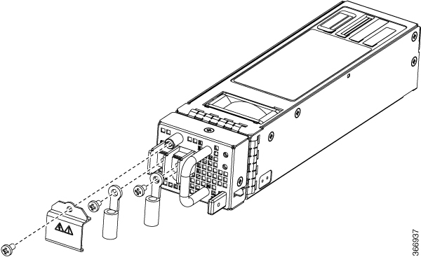
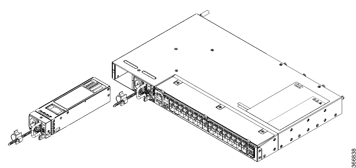
Replace Fan Module and Power Supply

Before you begin this task, ensure that you have read and understood the safety warnings in the Safety with Electricity section of the Safety Warnings handout topic.


Note


Replacing the fan module is applicable only for Cisco N540X-16Z4G8Q2C-A/D, N540-24Z8Q2C-SYS, N540X-ACC-SYS, and N540-ACC-SYS variants.


Note


Replacing power supply module is applicable only for Cisco N540-24Z8Q2C-SYS, N540X-16Z8Q2C-D, N540X-ACC-SYS, and N540-ACC-SYS variants.


Replace Fan Module


Caution


If you cannot replace a fan tray within three minutes, we recommend that you leave it in the chassis until you are prepared to replace it within that specified time limit.

Note


If you remove more than one fan tray at a time during operations, the router allows up to 2 minutes of operations before shutting down, unless you replace extra missing fan trays within that time. If the router senses an over temperature condition when multiple fan trays are removed, the shutdown can occur in less than 2 minutes.

Procedure


Step 1

Unscrew the captive thumbscrew at the front of the fan tray.
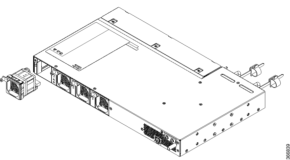
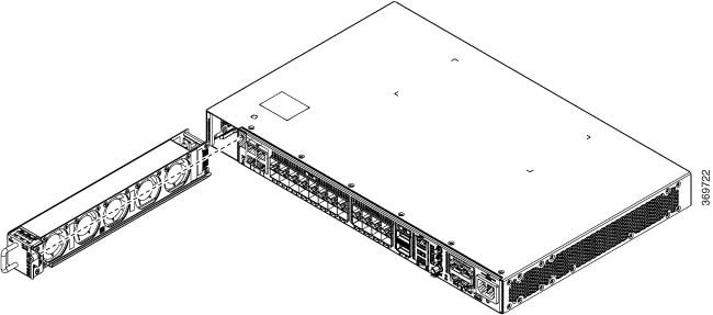
Figure 1. Remove Fan Module from the Chassis
Figure 2. Remove Fan Tray from the Chassis (N540X-16Z4G8Q2C-A)

Step 2

Pull the fan tray to remove the fan tray to be replaced.

Step 3

Hold the fan module with the LED and PID label at the top.

Step 4

Align the fan module to the open fan tray slot in the chassis and press the module all the way into the slot until the left and right latches click and lock on the chassis.

Step 5

If the chassis is powered on, listen for the fans. You should immediately hear them in operation. If you do not hear them, ensure that the fan module is inserted completely in the chassis.

Step 6

Verify that the fan module LED is green. If the LED is not green, one or more fans are faulty.


Replace Power Supply

The router provides a choice of two different power supplies:

  • DC power—The DC power supply uses two-position terminal block-style connector with positive latching or securing, and labeled connections for +24/48V, GRD, -24/48V. The terminal block connector is of suitable size to carry the appropriate AWG wire size to handle the input current of the power supply. No ON/OFF switch is provided.
  • AC power—The AC power supply has an IEC 320-type power receptacle and a 15 Amp service connector. You can use standard right angle power cords with the AC power supply. The power supply includes a power cord retainer. No ON/OFF switch is provided.

You can install dual power supplies for redundancy.


Note


Products that have an AC power connection are required to have an external SPD provided as part of the building installation to comply with the Telcordia GR-1089 NEBS standard for electromagnetic compatibility and safety.

Caution


Do not use interface module and power supply ejector handles to lift the chassis; using the handles to lift the chassis can deform or damage the handles.


PSU Redundancy Lost Alarm:

PSU redundancy lost alarms are generated when there is no proper input feed applied on any one of Power Modules (PMs) (PM0 or PM1). The alarms are also generated when the output for PM0 or PM1 is not proper.

Note


This is applicable to fixed PSUs only.


The following alarms are raised for PSU redundancy lost event with a faulty PM0:
  • Power Module Generic Fault

  • Power Module Error

  • Power Group Redundancy Lost

This is applicable to the following routers with fixed PSUs:
  • N540-28Z4C-SYS-A/D

  • N540X-16Z4G8Q2C-A/D

  • N540X-16Z8Q2C-D

  • N540-12Z20G-SYS-A/D

  • N540X-12Z16G-SYS-A/D

Remove the DC Power Supply Module

This section provides information about removing and replacing the DC power supply.


Warning


Statement 1003—DC Power Disconnection

To reduce risk of electric shock or personal injury, disconnect DC power before removing or replacing components or performing upgrades.


Follow these steps to remove and replace the DC power supply:

Procedure


Step 1

Before servicing the power supply, switch off the circuit breaker in your equipment area. As an additional precaution, tape the circuit-breaker switch in the Off position.

Step 2

Slip on the ESD-preventive wrist strap that is included in the accessory kit.

Step 3

Switch the power supply circuit-breaker switch to the Off (O) position.

Step 4

Pull the terminal block plug connector out of the terminal block head in the power supply. (See the following figure.)

Step 5

Loosen the captive screws on the DC power supply.

Step 6

Grasp the power supply handle. Press the power supply lock towards the left and simultaneously pull the power supply out from the chassis while supporting it with the other hand.


Install the DC Power Supply Module

This equipment is suitable for installation in Network Telecommunications Facilities and locations where the NEC applies.

This equipment is suitable for installations utilizing the Common Bonding Network (CBN).

The grounding architecture of this product is DC-Isolated (DC-I) for DC-powered products. DC-powered products have a nominal operating DC voltage of 48 VDC.

Perform the following procedure to install the power supply module:

Procedure


Step 1

Ensure that the system (earth) ground connection has been made. See the following figure.

Step 2

If necessary, remove the blank power supply filler plate from the chassis power supply bay opening by loosening the captive installation screws.

Step 3

Verify that power to the DC circuit connected to the power supply you are installing is off. To ensure that power has been removed from the DC circuits, locate the circuit breakers for the DC circuits, switch the circuit breakers to the OFF position, and tape the circuit-breaker switches in the OFF position.

Step 4

Grasp the power supply handle with one hand. Place your other hand underneath the power supply. Slide the power supply into the power supply bay. Make sure that the power supply is fully seated in the bay.

Step 5

Tighten the captive installation screws of the power supply. The recommended maximum torque is 5.5 in.-lb (0.62 N-m).

Figure 3. Install DC Power Supply Module

Remove the AC Power Supply Module

This section describes how to remove and replace the AC power supply.


Warning


Statement 1046—Installing or Replacing the Unit

To reduce risk of electric shock, when installing or replacing the unit, the ground connection must always be made first and disconnected last.

If your unit has modules, secure them with the provided screws.


Warning


Statement 1074—Comply with Local and National Electrical Codes

To reduce risk of electric shock or fire, installation of the equipment must comply with local and national electrical codes.


Follow these steps to remove and replace the AC power supply:

Procedure


Step 1

Disconnect the power cord from the power source. Do not touch any metal on the power cord when it is still connected to the power supply.

Step 2

Loosen the tie and remove the power cord from the tie-and holder.

Step 3

Remove the power cord from the power connection on the power supply. Do not touch the metal prongs embedded in the power supply.

Step 4

Grasp the power supply handle. Press the power supply lock towards the left and simultaneously pull the power supply out from the chassis while supporting it with the other hand.


Install the AC Power Supply Module

Follow these steps to install the AC power supply module:

Procedure


Step 1

Ensure that the system (earth) ground connection has been made.

Step 2

If necessary, remove the blank power supply filler plate from the chassis power supply bay opening by loosening the captive installation screws.

Step 3

Grasp the power supply handle with one hand. Place your other hand underneath the power supply. Slide the power supply into the power supply bay. Make sure that the power supply is fully seated in the bay. See the following figure.

Figure 4. Install AC Power Supply Module

Step 4

Slide the AC power supply cord inside the tie of the tie-and-holder and tighten the tie around the power supply cord.

Step 5

Plug the power supply cord into the AC power supply.