Space
Planning
This chapter provides information to help you determine where to install the Cisco CRS Series 16-Slot Line Card Chassis Enhanced router and to plan and prepare the site for the installation of the chassis. It describes the amount of space required for the chassis and provides information about floor loading and drill hole locations for securing the chassis to the floor. This chapter contains the following sections:
Basic CRS Routing System Floor Plans
As part of the site planning process, you must decide where to install the Cisco CRS 16-Slot Line Card Chassis Enhanced router. As you consider where to install the system, consider the following:
- Installation site floor plan must
include:
- Enough free space for the chassis (see the Cisco CRS 16-Slot Line Card Chassis Enhanced Router Footprint section).
- Adequate space for airflow and enough room to access chassis components for maintenance (see the Aisle Spacing and Maintenance Access Floor Plan section).
- Additional free space for potential expansion of the system (see the Planning for Future Expansion section).
- Slab or raised floor must support the weight of the chassis at the installation site (see the Chassis Floor Loading section).
- Cisco CRS 16-Slot Line Card Chassis Enhanced Router Footprint
- Aisle Spacing and Maintenance Access Floor Plan
- Planning for Future Expansion
Cisco CRS 16-Slot Line Card Chassis Enhanced Router Footprint
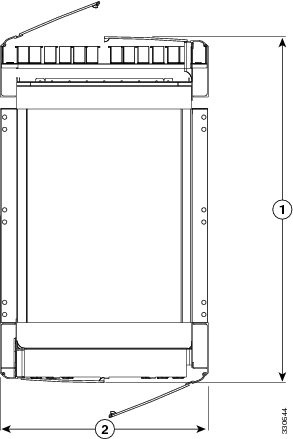
The following figure is a top view of the Cisco CRS 16-Slot Line Card Chassis Enhanced router footprint (with default front and rear cosmetics installed). The rear of the chassis is at the top of the figure.
|
1 |
39.7 in. (101 cm), with front and rear doors |
|
2 |
23.6 in. (60 cm), width of chassis, without handles |
 Note | A single-shelf (single chassis) system does not require chassis interconnect cabling; therefore, the rear door is optional. |
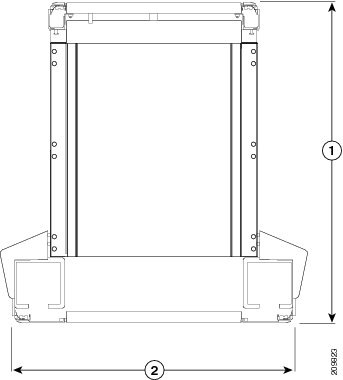
The following figure is a top view of the Cisco CRS 16-Slot Line Card Chassis Enhanced router footprint (with optional front cosmetics installed as part of a wide duct system). The rear of the chassis is at the top of the figure.
|
1 |
40.3 in. (102.2 cm) with wide troughs |
|
2 |
31.8 in. (80.8 cm) with wide troughs |
Aisle Spacing and Maintenance Access Floor Plan
Make sure that enough space exists at the installation site to install the Cisco CRS 16-Slot Line Card Chassis Enhanced router and allow sufficient airflow. The floor plan must also provide enough room to access chassis components for maintenance (for example, to remove fan trays, power modules, cables, and air filters). We recommend 48 in. (122 cm) clearance to install the chassis and 36 in. (91 cm) clearance to allow for access to chassis components.
-
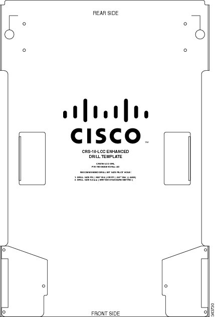
Aluminum plate template (CRS-16-DRILLTEMP) shows the chassis footprint and the pattern of holes that must be drilled into the floor for the mounting studs that secure the chassis to the floor. See the Anchoring the Chassis to the Floor section. See the following figure.
If you are configuration using standard troughs for cabling, unscrew and remove the side wings before placing and using the drill template. If you are using wide troughs, fold the side wings out and tighten to stabilize them before placing and using the drill template.
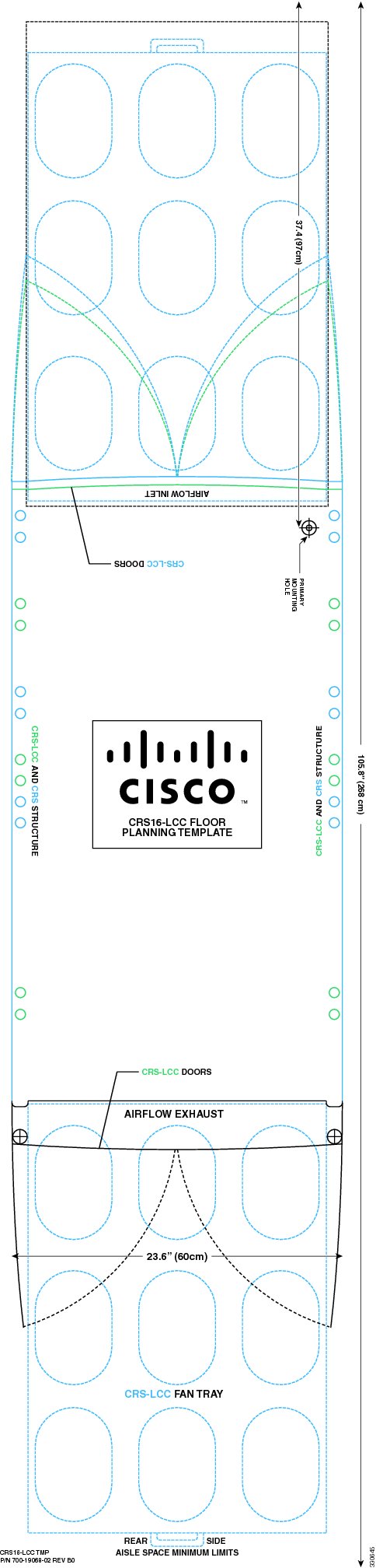
- Mylar template (CRS-16-FLOORTEMP) shows the chassis footprint, door swings, and required clearances to remove and replace chassis components. Use this template to plan the aisle space required for the installation and maintenance of a line card chassis. See the figure below.
Note | For front-to-front row alignment and back-to-back row alignment, we recommend that adjacent rows of chassis align the front intake to front intake or rear exhaust to rear exhaust. |
Note | The template shown in the following figure is only for space planning. Do not use this template as a drill template. |
Planning for Future Expansion
When planning the installation of the Cisco CRS Series system, consider potential expansion of the system, such as adding additional Cisco CRS 16-Slot Line Card Chassis Enhanced routers (single-shelf or multishelf system).
When planning for expansion, consider:
- Floor space for additional chassis or multishelf growth LCC to FCC
- Power and cooling requirements for additional chassis
- Cable management for additional interconnection cables and line card interface cables
- System management for the larger systems
Chassis Floor Loading
Whether you plan to install the chassis on slab concrete or raised floors, ensure that the floor is level and that it can support the weight of the chassis. See System Specifications for specifications on chassis weight and floor loading.
If you have 3-phase AC Delta or AC Wye at your site, a Cisco CRS 3-phase AC power distribution unit (PDU) will be required to convert 3-phase AC input power to single-phase AC input power for the power shelf. The following table lists the weight of the PDUs required to be installed for system redundancy, including cables and chassis-mounting brackets.
|
PDU Type |
Weight |
|---|---|
|
CRS-16 PDU (including two PDUs, cables and brackets) |
80 lb (36.3 kg) |
For more information about the Cisco CRS 3-Phase AC PDU, refer to the Cisco CRS 3-Phase AC Power Distribution Unit Installation Guide.
Anchoring the Chassis to the Floor
The Cisco CRS chassis must be anchored (bolted) to the floor at the installation site. To assist with this task, an aluminum plate template (CRS-16-DRILLTEMP) can be ordered. The template provides drill positions for the chassis mounting-hole locations.
The template shows the chassis footprint and the pattern of holes that must be drilled into the floor for the mounting studs that secure the chassis to the floor (see Figure 3. The template includes several mounting-hole locations:
- Primary—Use these mounting-hole locations whenever possible.
- Secondary—Use these locations if it is not possible to use the primary locations.
Slab Concrete Floors
Cisco has contracted with Hilti Corporation to provide a kit for installation of the Cisco CRS chassis on concrete floors. The kit contains instructions, fasteners, and washers. In addition, a hammer drill is required to install the studs. For more information, see the Cisco CRS Carrier Routing System 16-Slot Line Card Chassis Enhanced Router Unpacking, Moving, and Securing Guide.
Raised Floors
If you plan to install the line card chassis on a raised floor, be sure to follow local practices.
 Feedback