Cooling System Overview
The line card chassis cooling system dissipates the heat generated by the routing system and controls the temperature of components in the chassis. The cooling system has a fully redundant architecture that allows the routing system to continue operating with a single-fault failure (such as a single fan or fan tray failure). See Cooling System Redundancy for more information. The architecture also supports a redundant load-sharing design.
The complete chassis cooling system includes:
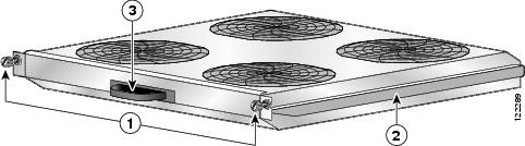
- Two fan trays; each fan tray contains four fans.
- Temperature sensors (on cards and modules throughout the chassis).
- Control software and logic.
- An air filter, inlet and outlet air vents, and bezels.
- Blanks and impedance carriers for empty chassis slots.
- Fixed configuration rectifiers and PEMs have own fans.
- Modular configuration AC and DC PMs have their own fans.
All four fans in a fan tray operate as a group. So if it is necessary to increase or decrease airflow, all fans in the tray increase or decrease their rotation speed together. When two fan trays are operational in a chassis, the speed of fans in both trays is adjusted together.
Thermal sensors (inlet, exhaust, and hot-spot) located throughout the line card chassis are used to monitor temperature readings and identify when the system is not cooling properly.
Software running on several types of service processor (SP) modules is used to control the operation of the fans. These SP modules are connected by internal Ethernet to the system controller on the route processor (RP).
Line Card Chassis Airflow
The airflow through the line card chassis is controlled by a push-pull configuration. The bottom fan tray pulls in ambient air from the bottom front of the chassis and the top fan pulls the air up through the card cages where the warm air is exhausted out the bottom rear of the chassis.
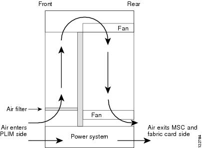
The line card chassis airflow volumes are as follows:
- Chassis airflow: Up to 900 cubic feet (25,485 liters) per minute
- Power system airflow: Up to 240 cubic feet (6,800 liters) per minute
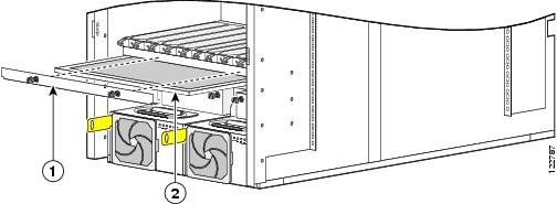
The chassis has a replaceable air filter mounted in a slide-out tray above the lower fan tray. The line card chassis air filter, shown in the next image , plugs into the rear (MSC) side of the chassis.
Change the air filter as often as necessary. In a dirty environment, or when you start getting frequent temperature alarms, check the intake grilles for debris and check the air filter to see if it needs to be replaced. Before removing the air filter for replacing, you should have a spare filter on hand. Then, when you remove the dirty filter, install the spare filter in the chassis.
 Note |
We recommend that you check the air filters once a month. Replace a filter when you notice a significant amount of dust. |
|
1 |
Air filter cover plate |
2 |
Chassis air filter |
Note |
A lattice of wire exists on both sides of the air filter with an arrow that denotes airflow direction and a pair of sheet metal straps on the downstream side of the filter assembly. |
Cooling System Operation
The fan control software and related circuitry varies the DC input voltage to individual fans to control their speed. This monitoring increases or decreases the airflow needed to keep the routing system operating in a desired temperature range. The chassis cooling system uses multiple fan speeds to optimize cooling, acoustics, and power consumption. There are four normal operating fan-speeds and one high-speed setting used when a fan tray has failed.
At initial power up, the routing system control software powers on the fans to 4,300 to 4,500 RPM. This provides airflow during system initialization and software boot, and ensures that there is adequate cooling for the system in case the software hangs during boot. The fan control software initializes after the routing system software boots, which can take three to five minutes. The fan control software then adjusts the fan speeds appropriately.
During normal operation, the system averages the temperatures reported by inlet temperature sensors in the card cage. To determine the appropriate fan speed for the current temperature, the fan control software compares the averaged inlet temperature to a lookup table that lists the optimal fan speed for each temperature. The software then sets the fan speed to the appropriate value for the current temperature. The temperature ranges in the lookup table overlap to ensure a proper margin to avoid any type of fan speed oscillation occurring between states.
Note |
When there are no active alarms or failures, the fan control software checks temperature sensors every one to two minutes. |
Thermal Alarms
Local thermal sensors (on individual cards) monitor temperatures and generate a thermal alarm when the system is not cooling properly. A temperature sensor might trip in response to elevated ambient air temperature, a clogged air filter or other airflow blockage, or a combination of these causes. A fan failure causes a fault message, but if no thermal sensors have tripped, the fan control remains unchanged.
When a thermal sensor reports a thermal alarm, the sensor passes the fault condition to its local service processor (SP), which then notifies the system controller on the route processor (RP). The system controller passes the fault condition to the SP. The fan control software then takes appropriate action to resolve the fault.
When a thermal sensor trips, the fan control software tries to resolve the problem (for example, by increasing fan speed). The software performs a series of steps to prevent chassis components from getting anywhere near reliability-reducing, chip-destroying temperatures. If the fault continues, the software shuts down the card or module to save components.
Quick-Shutdown Mode
The fan trays have a quick-shutdown mode that kills power when a card or fan tray is disengaged from the chassis midplane. The quick-shutdown mode minimizes inrush current during a hot swap or OIR. In normal maintenance conditions, the software gracefully shut downs the power to the failed part, allowing ample time for capacitors to discharge.
Cooling System Redundancy
The redundant architecture of the cooling system allows the cooling system to continue operating even when certain components have failed. The cooling system can withstand the failure of any one of the following components and still continue to properly cool the routing system:
- A fan tray
- DC PEM or AC rectifier
- A fan cable (internal to the chassis and not field replaceable)
A double-fault fan failure involves two fan trays, two power modules (DC PEMs or AC rectifiers), or any combination of two of these units. If a double-fault failure occurs, the system remains powered on, unless both fan trays have failed or thermal alarms indicate a problem serious enough to power down the system. The failure of multiple fans is not considered a double-fault failure because multiple fans can fail without impacting system cooling.
 Caution |
When a cooling system component fails, it should be replaced as soon as possible. |
 Feedback