Shipping and
Receiving
Shipping and Receiving
This chapter describes the issues to consider as you prepare to receive shipment of the Cisco CRS Carrier Routing System 16-Slot Line Card Chassis and transport the chassis components to the installation site.
It includes the following sections:
Receiving and Storing Routing System Components
When planning your Cisco CRS 16-slot line card chassis installation, you must consider how the routing system components will be moved from the shipping dock to the site where the chassis is to be installed. This section, and the sections that follow, provide information about the things to consider as you plan on how to transport the system components from the loading dock to the installation site.
The line card chassis is shipped in several crates that reduce the potential for product damage during routine material handling and shipment. To protect the chassis:
- Always store the chassis in its original packaging in an upright position.
- If you plan to store chassis components before the installation, be sure to store the components carefully and in their original shipping containers to prevent accidental damage.
 Note | When you are planning the transportation route and storage area, consider the shipping pallet and crate dimensions. (Table 1) |
Shipping Crates and Pallets
Depending on the number of options you ordered, the Cisco CRS router arrives packaged in several shipping crates and pallets. The line card chassis is shipped on a pallet by itself and arrives inside a polyethylene bag enclosed in a plywood box, held in place by steel clips (see the table below). Other system components are shipped in separate crates. For complete details on the contents of each crate, see the shipping and parts identification label on the crate.
 Caution | Do not stack the Cisco CRS shipping crates, because serious damage to the system components can occur. |
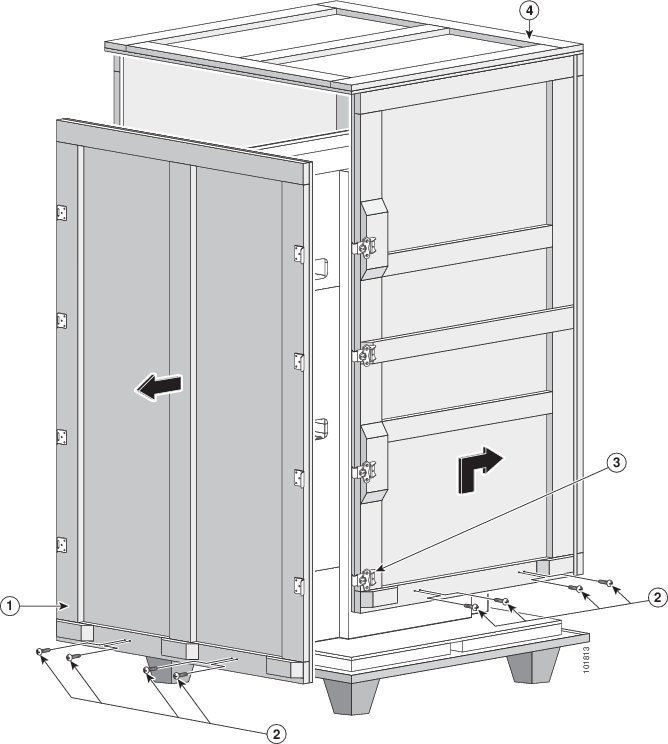
|
1 |
Lock latches |
3 |
Four-sided plywood box |
|
2 |
Large side panel |
|
|
The table below lists the physical characteristics of the chassis shipping crate.
|
Weight (Est. max.) |
1497 lb (679 kg)—Chassis in shipping crate with pallet |
|---|---|
|
Dimensions |
Height: 92 in. (233.7 cm) |
|
Width: 45 in. (114.3 cm) |
|
|
Length: 48 in. (121.9 cm) |
Unpacking and Storage of Chassis and Chassis Components
Consider the following as you plan for the unpacking and storage of chassis components:
- Make sure that enough room exists at the loading dock or installation site to unpack the system components. If you plan to store the components before installation, make sure that you have an area large enough in which to store the system components. Note that you should store components in their shipping crates until you are ready to install them.
- You should unpack the chassis and chassis components in the following order:
- Will you unpack
the chassis components from their shipping crates at the loading dock or
installation site? Consider the following:
- Are corridors and aisles from the loading dock to the installation site wide enough for the moving device and the chassis and components in their crates or pallets?
- To use the dolly supplied by Cisco to transport the chassis to the installation site, you must unpack the chassis to attach the dolly.
- If aisles are not wide enough, you might want to unpack components at the loading dock. Of course, you must make sure that there is enough room.
- Is there enough room at the installation site to unpack chassis components? If not, can system components be unpacked at the loading dock?
- Consider how you will move the chassis components from the shipping dock to the installation site. See the Transport to the Installation Site.
Transport to the Installation Site
This section describes the things to consider as you plan the route to use to move the chassis from the loading dock to the installation site. See Figure 1 for the minimum hallway, aisle, and doorway clearances required to accommodate the chassis.
Before you attempt to move the chassis to the installation site, we recommend that you check the proposed transport route and note any areas of concern. It might also be useful to create a diagram of the route you plan to take from the loading dock to the installation site.
Note | We recommend that at least two people move the chassis from the shipping dock to the installation site. |
- Is the installation site on a different floor than the loading dock? If so, are there freight elevators that can be used to transport the system components?
- Are there any ramps in the transport route? If so, the following guidelines apply:
- Are there any raised floors in the transport route or at the installation site that need to be protected while you move the chassis?
- Make sure that hallways, aisles, and doorways are high and wide enough to accommodate the chassis and moving device.
- Make sure that corners are wide enough for the chassis and moving device.
- Make sure that no obstacles exist in the transport route (for example, boxes or equipment in hallways, hanging wires, or items on the floor).
- Ensure that the dolly supplied by Cisco is available to transport the uncrated chassis from the shipping dock to the chassis final location.
Important Notice About Transporting the Chassis
Either a fork lift or pallet jack can be used to transport a crated chassis only.
Throughout this chapter we refer to the dolly (supplied by Cisco) as the required means to transport the uncrated chassis from the shipping dock to the chassis final location.
Note | In the event that the dolly supplied by Cisco is not the appropriate method of transportation, consult Cisco Technical Staff to determine a method of transportation appropriate for the site. Ensure that the alternate lifting device is capable of moving the chassis safely, supporting the weight of the chassis, and is capable of preventing the chassis from tipping. |
Caution | When using any type of device to transport the chassis, exercise extreme caution and follow proper safety practices. |
Using the dolly supplied by Cisco to Move the Chassis—Things to Consider
If you plan to use the dolly supplied by Cisco to move the chassis, consider the following:
- Dolly is optimized to move the chassis on flat surfaces. It is not designed to move the chassis up stairs, over curbs, up ramps greater than 1 inch of rise for every 6 inches of run, or over bumps more than 1.5 inch (3.8 cm) high, such as door thresholds.
- Before attaching the dolly, ensure that the power shelves, power modules, MSCs and PLIMs have been removed from the chassis. Ensure that impedance carriers have been installed to prevent dust and debris from entering the card cage during movement and installation.
- Whenever possible, use the dolly in the 180-degree configuration to move the chassis. Hallways and aisles must be at least 52 inches (132 cm) wide to accommodate the combined dolly and chassis width. The dolly in its 90-degree configuration requires 32 inches (81 cm) of hallway and aisle clearance, but requires extra care to avoid tipping the chassis.
For instructions on assembling and using the dolly supplied by Cisco, see the Cisco CRS Carrier Routing System 16-Slot Line Card Chassis Unpacking, Moving, and Securing Guide.
Verifying the Move Path
Before moving the chassis, it is critical that you verify that the path that you are planning to use to move the chassis to its final location can accommodate the chassis size and weight and the restrictions of the chassis when using the dolly (see the Planning for Future Expansion).
See the table below for a list of the restrictions for your move path, and verify that you have sufficient room for the entire move path before moving the chassis.
|
Specification |
Value |
|---|---|
|
Height (on dolly, with recommended 1 inch raise) |
81 in. (205 cm) |
|
Depth (on dolly, 90-degree dolly position) |
70 in. (177 cm) |
|
Depth (on dolly, 180-degree dolly position) |
48 in. (121 cm) |
|
Width (on dolly, 90-degree dolly position) |
24 in. (60 cm) |
|
Width (on dolly, 180-degree dolly position) |
44 in. (112 cm) |
|
Turning radius (on dolly, 90-degree dolly position) |
37 in. (94 cm) |
|
Turning radius (on dolly, 180-degree dolly position) |
33 in. (83 cm) |
|
Weight of chassis (as shipped, configuration, packaging removed) |
1175 lb (533 kg) (Estimated) |
|
Maximum curb height (chassis on dolly) |
1.5 in. (3.8 cm) |
Note | Allow a minimum gap of between 4 to 6 in. (10 to 15 cm) on each side of the combined chassis and dolly when moving it. |
The figure below shows the recommended minimum space to turn the chassis on the dolly in its 90-degree and 180-degree configuration.
|
1 |
Width (on dolly, 180-degree position) 44 in. (112 cm) |
4 |
Width (on dolly, 90-degree position) 24 in. (60 cm) |
|
2 |
Depth (on dolly, 180-degree position) 48 in. (122 cm) |
5 |
Depth (on dolly, 90-degree position) 70 in. (178 cm) |
|
3 |
Turn radius (on dolly, 180-degree position) 33 in. (83 cm) |
6 |
Turn radius (on dolly, 90-degree position) 37 in. (94cm) |
Then table below provides the dolly width and the recommended aisle width turning radius for the 90-degree and 180-degree dolly configuration.
|
Dolly Configuration |
Width of Combined Chassis and Dolly |
Recommended Aisle Width Turning Radius |
|---|---|---|
|
90-degree dolly position |
24 in. (60 cm) |
37 in. (94cm)1 |
|
180-degree dolly position |
44 in. (112 cm) |
33 in. (83 cm) |
The figure below is a top view of the minimum aisle space required to install the Cisco CRS 16-slot line card chassis without using the dolly supplied by Cisco.
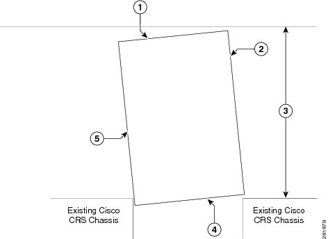
|
1 |
Chassis front |
4 |
Chassis rear |
|
2 |
Chassis side |
5 |
Chassis side |
|
3 |
Moving space requirement: 34.7 in. (95 cm) |
|
|
 Feedback