Cisco CRS Carrier Routing System 16-Slot Line Card Chassis Site Planning Guide
Bias-Free Language
The documentation set for this product strives to use bias-free language. For the purposes of this documentation set, bias-free is defined as language that does not imply discrimination based on age, disability, gender, racial identity, ethnic identity, sexual orientation, socioeconomic status, and intersectionality. Exceptions may be present in the documentation due to language that is hardcoded in the user interfaces of the product software, language used based on RFP documentation, or language that is used by a referenced third-party product. Learn more about how Cisco is using Inclusive Language.
- Updated:
- November 3, 2016
Chapter: System Planning Considerations
System Planning
Considerations
System Planning Considerations
This chapter describes the system planning considerations for your Cisco CRS Carrier Routing System 16-Slot Line Card Chassis installation. It includes the following sections:
- Planning for High Availability
- Power Redundancy and Card Placement for High Availability
- Power
- Cable Management
- Noise Control
- Cisco Installation Services
- System Testing, Certification, and Warranty
Planning for High Availability
Following is a list of tasks to configure the line card chassis for high availability, which helps to ensure that service is not disrupted due to failures:
- Install a redundant line card chassis, whose user interface links mirror the links on the other line card chassis. This way, if something happens to one line card chassis, the links are still operational on the other line card chassis.
To provide more high availability, also install each line card chassis in a different room, located in a different fire and power zone. This way, a problem in one room should not affect the operation of the other chassis.
- Run the power cables from each of the two power sources along different routes through the facility or at the installation site.
- Install PLIMs in specific line card chassis slots so that those links are not affected during a power failure. For example, you should distribute links to core and edge networks across PLIMs in different chassis slots so that a power failure does not affect the links. See the Line Card Chassis Load Zones and Card Placement for High Availability for more information.
- Run PLIM user interface cables along different routes.
See the following sections for information about the power redundancy features of the Cisco CRS routing system and information about how to install cards in the line card chassis to avoid the potential for service disruption during a power failure.
Power Redundancy and Card Placement for High Availability
This section describes the power redundancy features of the line card chassis. It describes the power load zones in the chassis and provides information about how to install cards to configure the chassis for high availability so that a power failure does not disrupt system operation.
The first several sections that follow provide information that applies to all chassis. The remaining sections describe specific features and considerations for individual chassis.
- Redundant Power Systems and Chassis Load Zones
- Line Card Chassis Load Zones and Card Placement for High Availability
- Using DRPs and DRP PLIMs to Increase Routing Performance
Redundant Power Systems and Chassis Load Zones
Each chassis power shelf is connected to a separate and independent power source (2N power redundancy). During normal operation when both power sources are operational, both sets of power shelves and power modules function together to power the chassis. If a power sources fails, the other power source provides enough input power to power the chassis. This 2N power redundancy enables the chassis to operate despite the power failure.
In addition, chassis load zones distribute power throughout the chassis and provide redundant power to chassis slots. In the modular configuration power system, all power modules power all chassis load zones, as long as the circuit breaker is not tripped. In the fixed configuration power system, each load zone is powered by a set of power modules (one module from each power shelf). In each set of power modules (A0 and B0, A1 and B1, and A2 and B2) each power module is considered a backup for the other. Each set of power modules provides power to the same set of chassis load zones. If either power module fails, the other continues to provide power to those slots.
Although it is rare, a double-fault power failure in a fixed configuration power system causes power to be lost to a load zone. A double-fault failure occurs when a power module and its backup module both fail. The failure results in all power being lost to a set of chassis slots, which means that the components or cards installed in those slots lose power and stop functioning until one of the failing power modules is replaced.
 Note | To avoid network connectivity disruption because of a double-fault power failure, you should carefully consider the best placement of cards in the chassis. See the Line Card Chassis Load Zones and Card Placement for High Availability for information about how to install cards to avoid a disruption in service. |
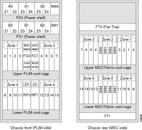
Figure 1 shows the load zones on the front (PLIM) and rear (MSC) side of the line card chassis.
Line Card Chassis Load Zones and Card Placement for High Availability
This section describes the power load zones in the line card chassis and provides information about how to install cards in the chassis so that a double-fault power failure does not disrupt service when a fixed configuration power system is installed. The figure below shows the load zones on the front and rear of the chassis with a fixed configuration power system installed.
To avoid service disruption because of a double-fault power failure in the line card chassis, consider the following to determine how to install modular services cards (MSCs), forwarding processor (FPs), and physical layer interface modules (PLIMs) in the chassis:
- Make sure that cards containing links to the core network are distributed across chassis load zones. For example, if all core-facing links are on cards in slots 0 through 3, a double-fault failure of power modules A0 and B0 would result in the Cisco CRS router not being able to communicate with other core routers in the network.
- In addition, make sure that cards containing links to downstream (edge) devices are distributed across chassis load zones. For example, if all edge-facing links are on cards in slots 12 through 15, a double-fault failure of power modules A2 and B2 would result in connectivity being lost to all downstream edge devices.
- Distribute cards across chassis load zones so that the loss of a load zone does not cause a single point of failure in the Cisco CRS router. For example, you want to ensure that the links to a particular system are not all lost if a double-fault failure occurs.
The table below shows an example of how you might install PLIMs in the line card chassis to avoid a single point of failure in the chassis. (This information is only an example. Your configuration may be different.)
|
Load Zone |
Slot |
Card Type 1 |
Card Connects to |
|---|---|---|---|
|
1 |
0 |
4xOC-192 |
Core or Intra-POP |
|
1 |
16xOC-48 |
Edge |
|
|
2 |
1xOC-768 |
Intra-POP |
|
|
3 |
8x10-GE |
Edge |
|
|
3 |
4 |
1xOC-768 |
Core |
|
5 |
8x10-GE |
Edge |
|
|
6 |
4xOC-192 |
Edge |
|
|
7 |
16xOC-48 |
Edge |
|
|
4 |
8 |
1xOC-768 |
Core |
|
9 |
8x10-GE |
Edge |
|
|
10 |
4xOC-192 |
Edge |
|
|
11 |
16xOC-48 |
Edge |
|
|
6 |
12 |
4xOC-192 |
Core or Intra-POP |
|
13 |
16xOC-48 |
Edge |
|
|
14 |
1xOC-768 |
Intra-POP |
|
|
15 |
8x10-GE |
Edge |
Using DRPs and DRP PLIMs to Increase Routing Performance
The Cisco CRS distributed route processor (DRP) and its companion card (DRP PLIM) are optional components that can be installed in the line card chassis to provide enhanced routing capabilities for Cisco CRS routers. The DRP is installed in any MSC slot. The DRP PLIM is installed in the corresponding PLIM slot.
- The DRP contains two symmetric multiprocessors (SMPs), each of which performs routing functions. Processor-intensive tasks (such as BGP speakers and ISIS) can be offloaded from the route processors (RPs) to the DRPs to improve the routing performance of the Cisco CRS router.
- The DRP PLIM contains RJ-45 ports to connect the DRP to the system management console for configuration and management. The DRP has no ports.
Power
Before installing a Cisco CRS routing system, you must carefully plan the facility power required to support it. The power requirements are based on the number of line card chassis that you plan to install. When planning the power layout for a routing system, you should also include the power requirements of peripheral equipment (such as the external terminals), the network management equipment, and the test equipment you will use with your system.
For larger system configurations, it may be advisable to consult with a facilities electrical expert to understand the load that a routing system may put on the power plant of your facility. Always follow local electrical codes.
Note | The chapter Power and Cooling Requirements provides detailed power and cooling requirements. |
Cable Management
As the size of the routing system increases, the cabling required for the chassis increases. For example, a fully loaded chassis has more cables connected to it than a partially loaded chassis.
The cabling runs must be carefully planned. The basic configurations for various routing systems should be arranged to minimize the complexity and length of the cable runs. Precut and terminated cables are considered part of the basic configuration.
Physical Layer Interface Module Cables
You must provide the line card- PLIM interface cables and the cable management trays for these cables from the line card chassis to your facility interconnect.
Because the type and number of MSCs, FPs, and PLIMS vary with each routing system site, plan these data cable runs in advance of the system installation.
When planning the data cable runs, consider the:
- Number and type of interface connections to PLIMs and SPAs
- MSC horizontal cable management tray
- Line card chassis vertical cable management
- Termination at the other end of the cables (patch panel, optical transport equipment, and so on)
- Proper length and termination of cables
Noise Control
The line card chassis has built-in noise reduction, such as fan speed control. If the chassis is installed in an environment in which excessive noise could be harmful to personnel, some other noise-reduction options could be attempted. Passive noise reduction could include the installation of foam panels to insulate the surrounding area from the noise.
Additional noise-reduction measures have to be designed on an individual customer basis.
Cisco Installation Services
Cisco or a Cisco partner can provide a total installation, from planning to power up. For information about Cisco (or Cisco partner) installation services, contact Cisco Customer Advocacy.
System Testing, Certification, and Warranty
After a Cisco CRS routing system has been installed, it has to be tested and certified. Contact Cisco Customer Advocacy for information about testing, certification, and warranties.
 Feedback