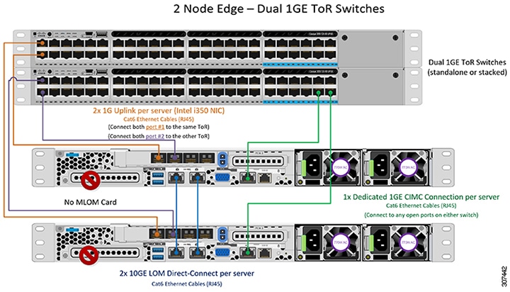
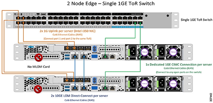
1GE Single Switch
Nexus 5548 using trunk ports
vlan 101
  name HX-MGMT
vlan 102
  name HX-STORAGE
vlan 103
  name HX-vMOTION
vlan 104
  name HX-GUESTVM
…
interface Ethernet2/11
  description HX-01-Port1
  switchport mode trunk
  switchport trunk allowed vlan 101-104
  spanning-tree port type edge trunk
  speed 1000
interface Ethernet2/12
  description HX-01-Port2
  switchport mode trunk
  switchport trunk allowed vlan 101-104
  spanning-tree port type edge trunk
  speed 1000
interface Ethernet2/13
  description HX-02-Port1
  switchport mode trunk
  switchport trunk allowed vlan 101-104
  spanning-tree port type edge trunk
  speed 1000
interface Ethernet2/14
  description HX-02-Port2
  switchport mode trunk
  switchport trunk allowed vlan 101-104
  spanning-tree port type edge trunk
  speed 1000
interface Ethernet2/15
  description HX-03-Port1
  switchport mode trunk
  switchport trunk allowed vlan 101-104
  spanning-tree port type edge trunk
  speed 1000
interface Ethernet2/16
  description HX-03-Port2
  switchport mode trunk
  switchport trunk allowed vlan 101-104
  spanning-tree port type edge trunk
  speed 1000
Catalyst 3850-48T using trunk ports
vlan 101
  name HX-MGMT
vlan 102
  name HX-STORAGE
vlan 103
  name HX-vMOTION
vlan 104
  name HX-GUESTVM
…
interface GigabitEthernet1/0/1
  description HX-01-Port1
  switchport trunk allowed vlan 101-104
  switchport mode trunk
  speed 1000
  spanning-tree portfast trunk
  interface GigabitEthernet1/0/2
  description HX-01-Port2
  switchport trunk allowed vlan 101-104
  switchport mode trunk
  speed 1000
  spanning-tree portfast trunk
interface GigabitEthernet1/0/3
  description HX-02-Port1
  switchport trunk allowed vlan 101-104
  switchport mode trunk
  speed 1000
  spanning-tree portfast trunk
  interface GigabitEthernet1/0/4
  description HX-02-Port2
  switchport trunk allowed vlan 101-104
  switchport mode trunk
  speed 1000
  spanning-tree portfast trunk
interface GigabitEthernet1/0/5
  description HX-03-Port1
  switchport trunk allowed vlan 101-104
  switchport mode trunk
  speed 1000
  spanning-tree portfast trunk
interface GigabitEthernet1/0/6
  description HX-03-Port2
  switchport trunk allowed vlan 101-104
  switchport mode trunk
  speed 1000
  spanning-tree portfast trunk
1GE Dual Switch
Nexus 5548 using trunk ports
This configuration uses DHCP with in-band management using native vlan 105. This switch connects to both 1GE LOMs and uses dhcp relay.
ip dhcp relay
…
interface Vlan105
  ip address 10.1.2.1/24
  ip dhcp relay address 10.1.1.2
  no shutdown
vlan 101
  name HX-MGMT
vlan 102
  name HX-STORAGE
vlan 103
  name HX-vMOTION
vlan 104
  name HX-GUESTVM
vlan 105
  name HX-DHCP-CIMC
…
interface Ethernet2/11
  description HX-01-Port1
  switchport mode trunk
  switchport trunk native vlan 105
  switchport trunk allowed vlan 101-105
  spanning-tree port type edge trunk
  speed 1000
interface Ethernet2/12
  description HX-01-Port2
  switchport mode trunk
  switchport trunk native vlan 105
  switchport trunk allowed vlan 101-105
  spanning-tree port type edge trunk
  speed 1000
interface Ethernet2/13
  description HX-02-Port1
  switchport mode trunk
  switchport trunk native vlan 105
  switchport trunk allowed vlan 101-105
  spanning-tree port type edge trunk
  speed 1000
interface Ethernet2/14
  description HX-02-Port2
  switchport mode trunk
  switchport trunk native vlan 105
  switchport trunk allowed vlan 101-105
  spanning-tree port type edge trunk
  speed 1000
interface Ethernet2/15
  description HX-03-Port1
  switchport mode trunk
  switchport trunk native vlan 105
  switchport trunk allowed vlan 101-105
  spanning-tree port type edge trunk
  speed 1000
interface Ethernet2/16
  description HX-03-Port2
  switchport mode trunk
  switchport trunk native vlan 105
  switchport trunk allowed vlan 101-105
  spanning-tree port type edge trunk
  speed 1000
Repeat the same configuration on switch #2. Eliminate the dhcp relay and interface Vlan 105 commands.
Catalyst 3850-48T using trunk ports
This configuration uses statically-assigned CIMC IPs on vlan 105. All vlans are allowed on all trunk interfaces. For security purposes, we recommend restricting the VLANs to those required for a HyperFlex
deployment by adding the switchport trunk allowed vlan statement into all your port configurations.
vlan 101
  name HX-MGMT
vlan 102
  name HX-STORAGE
vlan 103
  name HX-vMOTION
vlan 104
  name HX-GUESTVM
vlan 105
  name HX-CIMC
…
interface GigabitEthernet1/0/1
  description HX-01-Port1
  switchport mode trunk
  speed 1000
  spanning-tree portfast trunk
interface GigabitEthernet1/0/2
  description HX-01-Port2
  switchport mode trunk
  speed 1000
  spanning-tree portfast trunk
interface GigabitEthernet1/0/3
  description HX-02-Port1
  switchport mode trunk
  speed 1000
  spanning-tree portfast trunk
interface GigabitEthernet1/0/4
  description HX-02-Port2
  switchport mode trunk
  speed 1000
  spanning-tree portfast trunk
interface GigabitEthernet1/0/5
  description HX-03-Port1
  switchport mode trunk
  speed 1000
  spanning-tree portfast trunk
interface GigabitEthernet1/0/6
  description HX-03-Port2
  switchport mode trunk
  speed 1000
  spanning-tree portfast trunk
Repeat the same configuration on switch #2.
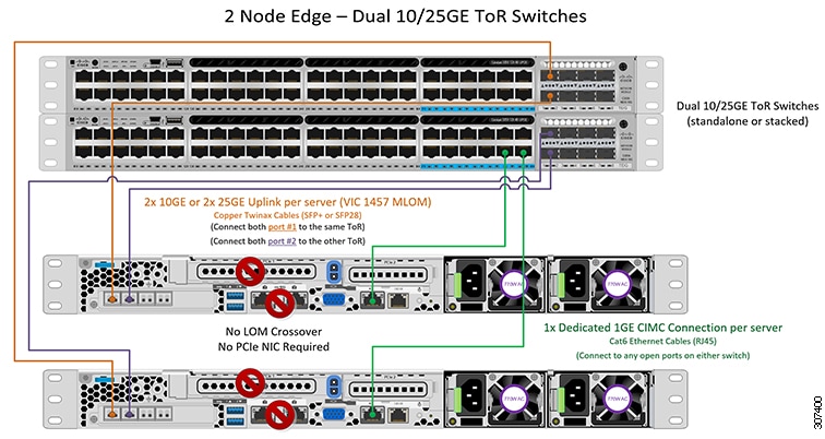
10GE Dual Switch
Nexus 9000 using trunk ports
vlan 101
   name HX-MGMT
vlan 102
   name HX-STORAGE
vlan 103
   name HX-vMOTION
vlan 104
   name HX-GUESTVM
vlan 105
   name HX-DHCP-CIMC
...
interface Ethernet1/35
  description M5-Edge-Node1-VIC1
  switchport mode trunk
  switchport trunk native vlan 105
  switchport trunk allowed vlan 101-105
  spanning-tree port type edge trunk

interface Ethernet1/36
  description M5-Edge-Node1-VIC2
  switchport mode trunk
  switchport trunk native vlan 105
  switchport trunk allowed vlan 101-105
  spanning-tree port type edge trunk

interface Ethernet1/37
  description M5-Edge-Node2-VIC1
  switchport mode trunk
  switchport trunk native vlan 105
  switchport trunk allowed vlan 101-105
  spanning-tree port type edge trunk

interface Ethernet1/38
  description M5-Edge-Node2-VIC2
  switchport mode trunk
  switchport trunk native vlan 105
  switchport trunk allowed vlan 101-105
  spanning-tree port type edge trunk

interface Ethernet1/39
  description M5-Edge-Node3-VIC1
  switchport mode trunk
  switchport trunk native vlan 105
  switchport trunk allowed vlan 101-105
  spanning-tree port type edge trunk

interface Ethernet1/40
  description M5-Edge-Node3-VIC2
  switchport mode trunk
  switchport trunk native vlan 105
  switchport trunk allowed vlan 101-105
  spanning-tree port type edge trunk
Catalyst 9300 using trunk ports
vlan 101
  name HX-MGMT
vlan 102
  name HX-STORAGE
vlan 103
  name HX-vMOTION
vlan 104
  name HX-GUESTVM
vlan 105
  name HX-CIMC
…
interface GigabitEthernet1/0/1
 description M5-Edge-16W9-LOM1
 switchport trunk allowed vlan 101-105
 switchport mode trunk
 spanning-tree portfast trunk

interface GigabitEthernet1/0/2
 description M5-Edge-16W9-LOM2
 switchport trunk allowed vlan 101-105
 switchport mode trunk
 spanning-tree portfast trunk

interface GigabitEthernet1/0/3
 description M5-Edge-16UQ-LOM1
 switchport trunk allowed vlan 101-105
 switchport mode trunk
 spanning-tree portfast trunk

interface GigabitEthernet1/0/4
 description M5-Edge-16UQ-LOM2
 switchport trunk allowed vlan 101-105
 switchport mode trunk
 spanning-tree portfast trunk

interface GigabitEthernet1/0/5
 description M5-Edge-05G9-LOM1
 switchport trunk allowed vlan 101-105
 switchport mode trunk
 spanning-tree portfast trunk

interface GigabitEthernet1/0/6
 description M5-Edge-05G9-LOM2
 switchport trunk allowed vlan 101-105
 switchport mode trunk
 spanning-tree portfast trunk
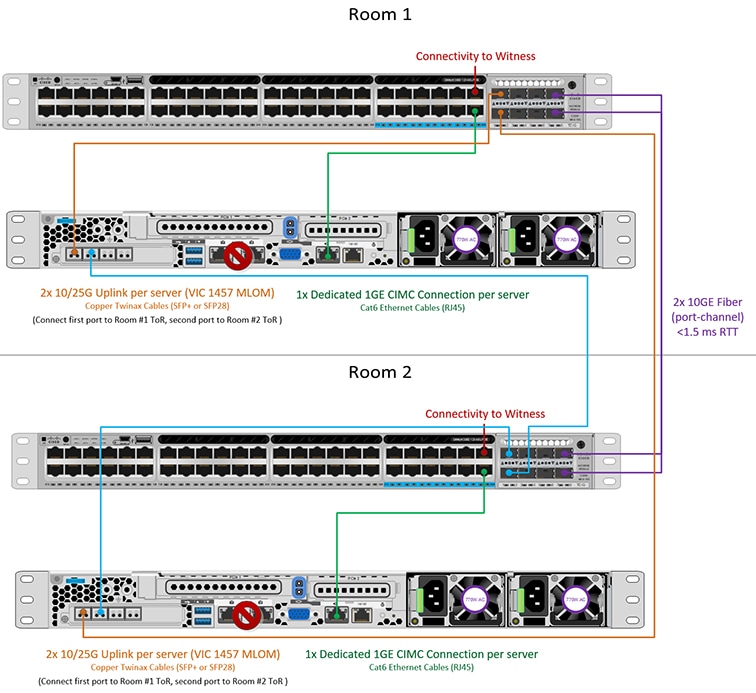
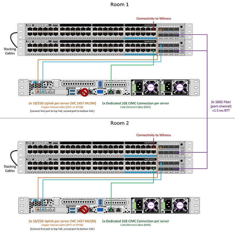
10/25GE 2-Node 2-Room
Catalyst 9300 with QoS
This configuration uses quality of service to mark and prioritize HyperFlex storage traffic using the 10 or 25 Gigabit Ethernet
Stacked Switches Per Room Topology
class-map match-all PQ_Storage
 match dscp ef
class-map match-all Storage
 match access-group name Storage
...
policy-map Storage_Mark
 class Storage
  set dscp ef
 class class-default
policy-map Storage_Queue
 class PQ_Storage
  priority level 1
  queue-buffers ratio 80
 class class-default
  bandwidth remaining percent 100
  queue-buffers ratio 20
...
interface Port-channel98
 switchport trunk allowed vlan 101,102,103,104,105
 switchport mode trunk
!
interface GigabitEthernet1/0/3
 description SERVER1-Dedicated-CIMC
 switchport access vlan 145
 switchport mode access
 spanning-tree portfast
!
interface TenGigabitEthernet1/1/1
 description SERVER1-VIC-1
 switchport trunk allowed vlan 101,102,103,104,105
 switchport mode trunk
 spanning-tree portfast trunk
 service-policy input Storage_Mark
!
interface TenGigabitEthernet2/1/1
 description SERVER1-VIC-2
 switchport trunk allowed vlan 101,102,103,104,105
 switchport mode trunk
 spanning-tree portfast trunk
 service-policy input Storage_Mark
!

interface TenGigabitEthernet1/1/8
 description cross-connect-01
 switchport trunk allowed vlan 101,102,103,104,105
 switchport mode trunk
 channel-group 98 mode on
 service-policy output Storage_Queue
!
interface TenGigabitEthernet2/1/8
 description cross-connect-02
 switchport trunk allowed vlan 101,102,103,104,105
 switchport mode trunk
 shutdown
 channel-group 98 mode on
 service-policy output Storage_Queue
!
...
ip access-list extended Storage
 10 permit ip 169.254.1.0 0.0.0.255 169.254.1.0 0.0.0.255
Repeat the same configuration on switch stack #2.


 Feedback