Configure Cisco HyperFlex Systems

This chapter describes how to configure the components of the Cisco HyperFlex Systems:

Installation Workflow


Note


If the HyperFlex cluster nodes were part of any other HyperFlex cluster before (or not factory shipped), follow the node cleanup procedure before starting the cluster deployment. For more information , see HyperFlex Customer Cleanup Guides for FI and Edge.

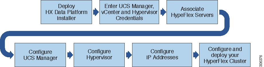
The following installation workflow summarizes the steps involved in creating a Standard Cluster, using the HX Data Platform Installer.

Follow this workflow during installation:

  1. Deploy the HX Data Platform Installer OVA using the vSphere Web Client. If your hypervisor wizard defaults to DHCP for assigning IP addresses to new VMs, deploy the HX Data Platform Installer OVA with a static IP address. See Deploy HX Data Platform Installer OVA Using vSphere Web Client or Deploy the HX Data Platform Installer OVA with a Static IP Address for more information.

  2. Configure syslog to send all logging information to a centralized syslog repository. See Configure Syslog for more information.

  3. Enter UCS Manager, vCenter, and Hypervisor credentials.

  4. Configure server ports and associate HyperFlex servers. See Associate HyperFlex Serversfor more information.

  5. Configure VLAN, MAC Pool, 'hx-ext-mgmt' IPPool for Out-of-Band CIMC, iSCSi Storage, and FC Storage. See Configure UCS Manager for more information.

  6. Configure the Hypervisor. See Configure Hypervisor for more information.

  7. Configure the IP addresses. See Configure IP Addresses for more information.

  8. Configure and deploy the HyperFlex cluster. See Configure Your HyperFlex Cluster for more information.

Deploy HX Data Platform Installer OVA Using vSphere Web Client

In addition to installing the HX Data Platform on an ESXi host, you may also deploy the HX Data Platform Installer on either VMware Workstation, VMware Fusion, or Virtual Box.


Note


  • Connect to vCenter to deploy the OVA file and provide the IP address properties. Deploying directly from an ESXi host will not allow you to set the values correctly.

  • Do not deploy the HX Data Platform Installer to an ESXi server that is going to be a node in the Cisco HX Storage Cluster.


Procedure


Step 1

Locate and download the HX Data Platform Installer OVA from Download Software. Download the HX Data Platform Installer to a node that is on the storage management network, which will be used for the HX Data Platform storage cluster.

Example:
Cisco-HX-Data-Platform-Installer-v5.0.1a-26363.ova

Step 2

Deploy the HX Data Platform Installer using VMware hypervisor, to create a HX Data Platform Installer virtual machine.

Note


Use a release of the virtualization platform that supports virtual hardware version 10.0 or greater.

vSphere is a system requirement. You can use either vSphere thick client, vSphere thin client, or vSphere Web Client. To deploy the HX Data Platform Installer, you can also use VMware Workstation, VMware Fusion, or VirtualBox.

  1. Open a virtual machine hypervisor, such as vSphere, VirtualBox, Workstation, or Fusion.

  2. Select the node where you want to deploy the HX Data Platform Installer.

    Important


    Ensure that you provide user credentials while deploying the HX Installer OVA using vSphere Web Client.

    • Using vSphere thick Client—Expand Inventory list > Host > File > Deploy OVA.

    • Using vSphere Web Client—Expand vCenter Inventory list > Hosts > Host > Deploy OVA.

Step 3

Select where the HX Data Platform Installer is located. Accept the defaults, and select the appropriate network.

Step 4

Enter a static IP address for use by the HX Data Platform Installer VM.

Note

 
  • Static IP Address is necessary even if DHCP is configured for the network. You need the static IP address to run the HX Data Platform Installer, to install the HX Data Platform, and to create the HX Data Platform storage cluster.

  • If your hypervisor wizard defaults to DHCP for assigning IP addresses to new VMs, then complete the steps in Deploy the HX Data Platform Installer OVA with a Static IP Address, to install the HX Data Platform Installer VM with a static IP address. DNS must be reachable from the Installer VM.

Field

Description

Hostname

The hostname for this VM.

Leave blank to try to reverse lookup the IP address.

Default Gateway

The default gateway address for this VM.

Leave blank if DHCP is desired.

DNS

The domain name servers for this VM (comma separated).

Leave blank if DHCP is desired.

IP Address

The IP address for this interface.

Leave blank if DHCP is desired.

Netmask

The netmask or prefix for this interface.

Leave blank if DHCP is desired.

Root Password

The root user password.

This field is a required field.

Step 5

Click Next. Verify if the options listed are correct and select Power on after deployment.

To power on the HX Data Platform Installer manually, navigate to the virtual machine list and power on the installer VM.

Note


The preferred settings for the HX Data Platform Installer virtual machine is 3 vCPU and 4 GB of memory. Reducing these settings can result in 100% CPU usage and spikes for the host.

Step 6

Click Finish. Wait for the HX Data Platform Installer VM to be added to the vSphere infrastructure.

Step 7

Open the HX Data Platform Installer virtual machine console.

The initial console display lists the HX Data Platform Installer virtual machine IP address.

Data Platform Installer.
*******************************************
You can start the installation by visiting
the following URL:
http://192.168.10.210
*******************************************
Cisco-HX-Data-Platform-Installer login:

Step 8

Use the URL to log in to the HX Data Platform Installer.

Example:
http://192.168.10.210

Step 9

Accept the self-signed certificate.

Step 10

Log in using the username root and the password you provided as part of the OVA deployment.


Deploy the HX Data Platform Installer OVA with a Static IP Address

If your hypervisor wizard defaults to DHCP for assigning IP addresses to new VMs, deploy the HX Data Platform Installer using the following steps:

Procedure


Step 1

Install the VMware OVF Tool 4.1 or later on a node that is on the storage management network that will be used for the HX Data Platform storage cluster. See OVF Tool Documentation for more details.

Step 2

Locate and download HX Data Platform installer OVA from Download Software on the node where VMware OVF was installed.

Step 3

Deploy the downloaded HX Data Platform installer OVA, using the ovftool command. For example:

root@server:/tmp/test_ova# ovftool --noSSLVerify --diskMode=thin
--acceptAllEulas=true --powerOn --skipManifestCheck --X:injectOvfEnv
--datastore=qa-048-ssd1 --name=rfsi_static_test1 --network='VM Network'
--prop:hx.3gateway.Cisco_HX_Installer_Appliance=10.64.8.1
--prop:hx.4DNS.Cisco_HX_Installer_Appliance=10.64.1.8
--prop:hx.5domain.Cisco_HX_Installer_Appliance=cisco
--prop:hx.6NTP.Cisco_HX_Installer_Appliance=10.64.8.5
--prop:hx.1ip0.Cisco_HX_Installer_Appliance=10.64.8.36
--prop:hx.2netmask0.Cisco_HX_Installer_Appliance=255.255.248.0
--prop:hx.7root_password.Cisco_HX_Installer_Appliance=mypassword
/opt/ovf/rfsi_test/Cisco-HX-Data-Platform-Installer-v1.7.1-14786.ova
vi://root:password@esx_server

The command deploys the HX Data Platform installer, powers on the HX Data Platform installer VM, and configures the provided static IP address. A sample of processing response:

Opening OVA source:
/opt/ovf/rfsi_test/Cisco-HX-Data-Platform-Installer-v1.7.1-14786.ova
Opening VI target: vi://root@esx_server:443/
Deploying to VI: vi://root@esx_server:443/
Transfer Completed
Powering on VM: rfsi_static_test
Task Completed
Completed successfully

DNS must be reachable from the Installer VM. The required command options for the static IP address to be configured successfully are:

Command

Description

powerOn

To power on the HX Data Platform installer VM after it is deployed.

X:injectOvfEnv

To insert the static IP properties onto the HX Data Platform installer VM.

prop:hx.3gateway.Cisco_HX_Installer_Appliance=10.64.8.1

Specify the appropriate gateway IP address.

prop:hx.4DNS.Cisco_HX_Installer_Appliance=10.64.1.8

Specify the appropriate DNS IP address.

prop:hx.5domain.Cisco_HX_Installer_Appliance=cisco

Specify the appropriate domain.

prop:hx.6NTP.Cisco_HX_Installer_Appliance=10.64.8.5

Specify the appropriate NTP IP address.

prop:hx.1ip0.Cisco_HX_Installer_Appliance=10.64.8.36

Specify the appropriate installer static IP address.

prop:hx.2netmask0.Cisco_HX_Installer_Appliance=255.255.248.0

Specify the appropriate netmask address.

prop:hx.7root_password.Cisco_HX_Installer_Appliance=mypassword

Specify the root user password.

/opt/ovf/rfsi_test/Cisco-HX-Data-Platform-Installer-v1.7.1-14786.ova

The source address of the HX Data Platform installer OVA.

vi://root:password@esx_server

The destination ESX server where the HX Data Platform installer VM is installed. Include the appropriate ESX server root login credentials.


Configure Syslog

It is best practice to send all logging information to a centralized syslog repository.


Attention


In general, configuring audit log export using syslog is recommended if long term retention of audit log is required. Specifically, for HX220c nodes and compute-only nodes booting from SD card, configuring syslog is required for persistent logging. If you do not configure the syslog server, audit logs are overwritten because of the log rotation policy.


Note


You cannot select an NFS datastore as a destination for the persistent scratch location on ESXi. If you select the HX datastore for the persistent scratch location, it will be removed after the ESXi host reloads.

For all M5 and M6 servers, M.2 boot SSD is automatically selected for use as scratch. This is configured out of the box on any new install.

For HX240M4 (non-SED), Intel SSD is used for persistent logs/scratch (same applies on 220M5/240M5, but on a different local SSD).

For HX220M4 and HX240M4 (SED), there is no location to store the scratch partition. So, the only option is to use syslog for persistent logging over the network.


Procedure


Step 1

Verify that the syslog server is up and running and TCP/UDP ports are open to receive logs from ESXi servers.

Step 2

SSH to the ESXi shell and execute the following commands.

a) esxcli system syslog config set --loghost='udp://remote-syslog-server-ip'
b) esxcli system syslog reload
c) esxcli network firewall ruleset set -r syslog -e true
d) esxcli network firewall refresh

Step 3

Repeat steps 1 and 2 for all ESXi hosts in the cluster.

Step 4

At the remote syslog server, verify if the logs are being received in the designated directory.


Configure and Deploy Your HyperFlex Cluster

Associate HyperFlex Servers

On the Server Selection page, the Configuration pane on the right displays a detailed list of the Credentials used. The Server Selection page displays a list of unassociated HX servers under the Unassociated tab, and the list of discovered servers under the Associated tab.

Field

Description

Locator LED

Turn on to locate a server.

Server Name

Name assigned to the server.

Status

  • Inaccessible—

Model

Displays the server model.

Serial

Displays the serial number of the server.

Assoc State

  • Associated

  • Unassociated

Service Profile [Only for Associated Servers]

Service profile assigned to the server.

Note


Editing the HyperFlex Service Profile templates is not recommended.

Actions

  • Launch KVM Console—Choose this option to launch the KVM Console directly from the HX Data Platform Installer.

  • Disassociate Server—Choose this option to remove a service profile from that server.

Before you begin

Ensure that you completed entering UCS Manager, vCenter, and Hypervisor credentials.

Procedure


Step 1

Click the Configure Server Ports button to discover any new HX nodes. In the Configure Server Ports dialog box, list all ports to be configured as server ports. Click Configure.

Note


Typically, the server ports are configured in Cisco UCS Manager before you start the configuration.

Step 2

Select the servers under the Unassociated tab to include in the HyperFlex cluster.

If HX servers do not appear in this list, check Cisco UCS Manager and ensure that they have been discovered.

Note


If there are no unassociated servers, the following error message is displayed:

No unassociated servers found. Login to UCS Manager and ensure server ports are enabled. 

Step 3

Click Continue to configure UCS Manager. See Configure UCS Manager.


Configure UCS Manager

On the UCSM Configuration page, you can configure VLAN, MAC Pool, 'hx-ext-mgmt' IP Pool for CIMC, iSCSi Storage, and FC Storage.

Before you begin

Associate servers to the HyperFlex cluster. See Associate HyperFlex Servers.

Procedure


Step 1

In the VLAN Configuration section, complete the following fields:

Note


Use separate subnet and VLANs for each of the following networks.

Field

Description

VLAN for Hypervisor and HyperFlex management

VLAN Name

hx-inband-mgmt

VLAN ID

Default—3091

VLAN for HyperFlex storage traffic

VLAN Name

hx-storage-data

VLAN ID

No default value.

VLAN for VM vMotion

VLAN Name

hx-vmotion

VLAN ID

Default—3093

VLAN for VM Network

VLAN Name

vm-network

VLAN ID(s)

Default—3094

A comma-separated list of guest VLANs.

Step 2

In the MAC Pool section, configure MAC Pool Prefix by adding in two more hex characters (0-F).

Note


Select a prefix that is not used with any other MAC address pool across all UCS domains.

Example:
00:25:B5:A0:

Step 3

In the 'hx-ext-mgmt' IP Pool for CIMC section, complete the following fields:

Field

Description

IP Blocks

The range of management IP addresses assigned to the CIMC for each HyperFlex server. The IP addresses are specified as a range, and multiple blocks of IPs may be specified as a comma-separated list. Ensure you have at least one unique IP per server in the cluster. When selecting to use out-of-band, this range must fall into the same IP subnet used on the mgmt0 interfaces on the Fabric Interconnects.

For example, 10.193.211.124-127, 10.193.211.158-163.

Subnet Mask

Specify the subnet mask for the IP range provided above.

For example, 255.255.0.0.

Gateway

Enter the Gateway IP address.

For example, 10.193.0.1.

The management IP addresses used to access the CIMC on a server can be either:
  • Out of band: The CIMC management traffic traverses the Fabric Interconnect through the limited bandwidth management interface, mgmt0, on the Fabric Interconnect. This option is most commonly used and shares the same VLAN as the Fabric Interconnect management VLAN.

  • In-band: The CIMC management traffic traverses the Fabric Interconnect through the uplink ports of the Fabric Interconnect. The bandwidth available for management traffic in this case would be equivalent to the Fabric Interconnect uplink bandwidth. If you are using the In-band option, the Cisco HyperFlex installer will create a dedicated VLAN for the CIMC management communication. This option is useful when large files such as a Windows Server installation ISO must be mounted to the CIMC for OS installation. This option is only available in the HyperFlex installer VM and is not available for deployments through Intersight.

Step 4

Select either Out of band or In-band based on the type of connection you want to use for CIMC management access. If you select In-band, provide the VLAN ID for the management VLAN. Make sure to create the CIMC management VLAN in the upstream switch for seamless connectivity.

Step 5

If you want to add external storage, configure iSCSI Storage by completing the following fields:

Field

Description

Enable iSCSI Storage check box

Select to configure iSCSI storage.

VLAN A Name

Name of the VLAN associated with the iSCSI vNIC, on the primary Fabric Interconnect (FI-A).

VLAN A ID

ID of the VLAN associated with the iSCSI vNIC, on the primary Fabric Interconnect (FI-A).

VLAN B Name

Name of the VLAN associated with the iSCSI vNIC, on the subordinate Fabric Interconnect (FI-B).

VLAN B ID

ID of the VLAN associated with the iSCSI vNIC, on the subordinate Fabric Interconnect (FI-A).

Step 6

If you want to add external storage, configure FC Storage by completing the following fields:

Field

Description

Enable FC Storage check box

Select to enable FC Storage.

WWxN Pool

A WWN pool that contains both WW node names and WW port names. For each Fabric Interconnect, a WWxN pool is created for WWPN and WWNN.

VSAN A Name

The name of the VSAN for the primary Fabric Interconnect (FI-A).

Default—hx-ext-storage-fc-a.

VSAN A ID

The unique identifier assigned to the network for the primary Fabric Interconnect (FI-A).

Caution


Do not enter VSAN IDs that are currently used on the UCS or HyperFlex system. If you enter an existing VSAN ID in the installer which utilizes UCS zoning, zoning will be disabled in your existing environment for that VSAN ID.

VSAN B Name

The name of the VSAN for the subordinate Fabric Interconnect (FI-B).

Default—hx-ext-storage-fc-b.

VSAN B ID

The unique identifier assigned to the network for the subordinate Fabric Interconnect (FI-B).

Caution


Do not enter VSAN IDs that are currently used on the UCS or HyperFlex system. If you enter an existing VSAN ID in the installer which utilizes UCS zoning, zoning will be disabled in your existing environment for that VSAN ID.

Step 7

In the Advanced section, do the following:

Field

Description

UCS Server Firmware Release

Select the UCS firmware release to associate with the HX servers from the drop-down list. The UCS firmware release must match the UCSM release. See the latest Cisco HX Data Platform Release Notes for more details.

For example, 3.2(1d).

HyperFlex Cluster Name

Specify a user-defined name. The HyperFlex cluster name is applied to a group of HX Servers in a given cluster. The HyperFlex cluster name adds a label to service profiles for easier identification.

Org Name

Specify a unique Org Name to ensure isolation of the HyperFlex environment from the rest of the UCS domain.

Step 8

Click Continue to configure the Hypervisor. See Configure Hypervisor.


Configure Hypervisor


Note


Review the VLAN, MAC pool, and IP address pool information on the Hypervisor Configuration page, in the Configuration pane. These VLAN IDs may be changed by your environment. By default, the HX Data Platform Installer sets the VLANs as non-native. You must configure the upstream switches to accommodate the non-native VLANs by appropriately applying a trunk configuration.


Attention


You can skip configuring Hypervisor in case of a reinstall, if ESXi networking has been completed.

Before you begin

Configure VLAN, MAC Pool, and 'hx-ext-mgmt' IP Pool for Out-of-Band CIMC. If you are adding external storage, configure iSCSI Storage and FC Storage. Select the UCS Server Firmware Version and assign a name for the HyperFlex cluster. See Configure UCS Manager.

Procedure


Step 1

In the Configure Common Hypervisor Settings section, complete the following fields:

Field

Description

Subnet Mask

Set the subnet mask to the appropriate level to limit and control IP addresses.

For example, 255.255.0.0.

Gateway

IP address of gateway.

For example, 10.193.0.1.

DNS Server(s)

IP address for the DNS Server.

Note

 
  • If you do not have a DNS server, do not enter a hostname in any of the fields on the Cluster Configuration page of the HX Data Platform Installer. Use only static IP addresses and hostnames for all ESXi hosts.

  • If you are providing more than one DNS server, check carefully to ensure that both DNS servers are correctly entered, separated by a comma.

Step 2

On the Hypervisor Settings section, select Make IP Addresses and Hostnames Sequential to make the IP addresses sequential. Complete the following fields:

Note


You can rearrange the servers using drag and drop.

Field

Description

Name

Name assigned to the server.

Locator LED

Turn on to locate a server.

Serial

Displays the serial number of the server.

Static IP Address

Input static IP addresses and hostnames for all ESXi hosts.

Hostname

Do not leave the hostname fields empty.

Step 3

Click Continue to configure IP Addresses. See Configure IP Addresses.


Configure IP Addresses

Before you begin

Ensure that you completed configuring Hypervisor on the Hypervisor Configuration page. See Configure Hypervisor.

Procedure


Step 1

On the IP Addresses page, select Make IP Addresses Sequential to make the IP Addresses sequential.

Step 2

When you enter IP addresses in the first row for Hypervisor, Storage Controller (Management) and Hypervisor, Storage Controller (Data) columns, the HX Data Platform Installer incrementally autofills the node information for the remaining nodes. The minimum number of nodes in the storage cluster is three. If you have more nodes, use the Add button to provide the address information.

Note


Compute-only nodes can be added only after the storage cluster is created.

For each HX node, enter the Hypervisor, Storage Controller, Management, and Data IP addresses. For the IP addresses, specify if the network belongs to the Data Network or the Management Network.

Field

Description

Management Hypervisor

Enter the static IP address that handles the Hypervisor management network connection between the ESXi host and the storage cluster.

Management Storage Controller

Enter the static IP address that handles the storage controller VM management network connection between the storage controller VM and the storage cluster.

Data Hypervisor

Enter the static IP address that handles the Hypervisor data network connection between the ESXi host and the storage cluster.

Data Storage Controller

Enter the static IP address that handles the storage controller VM data network connection between the storage controller VM and the storage cluster.

Step 3

The IP address provided here are applied to one node in the storage cluster. In the event the node becomes unavailable the affected IP address is moved to another node in the storage cluster. All nodes must have a port configured to accept these IP addresses.

Provide the following IP addresses:

Field

Description

Management Cluster Data IP Address

Enter the management network IP address for the HX Data Platform storage cluster.

Data Cluster Data IP Address

Enter the IP address of data network for the HX Data Platform storage cluster.

Management Subnet Mask

Enter the subnet information for your VLAN and vSwitches.

Provide the management network value. For example, 255.255.255.0.

Data Subnet Mask

Provide the network value for the data network. For example, 255.255.255.0.

Management Gateway

Provide the network value for your management network. For example, 10.193.0.1.

Data Gateway

Provide the network value for your data network. For example, 10.193.0.1.

Step 4

Click Continue to configure the HyperFlex cluster. See Configure Your HyperFlex Cluster.


Configure Your HyperFlex Cluster

On the Cluster Configuration page, for the Cisco HX Storage Cluster complete the following fields to begin deploying the HyperFlex cluster.

Before you begin

Ensure that you completed configuring IP addresses on the IP Addresses page. See Configure IP Addresses.

Procedure


Step 1

In the Cisco HX Cluster section, complete the following fields:

Field

Description

Cluster Name

Specify a name for the HX Data Platform storage cluster.

Replication Factor

Specify the number of redundant replicas of your data across the storage cluster. Set the replication factor to either 2 or 3 redundant replicas.

  • For hybrid servers (servers that contain SSD and HDDs), the default value is 3.

  • For flash servers (servers that contain only SSDs), select either 2 or 3.

  • A replication factor of three is highly recommended for all environments except HyperFlex Edge. A replication factor of two has a lower level of availability and resiliency. The risk of outage due to component or node failures should be mitigated by having active and regular backups.

Step 2

In the Controller VM section, create a new password for the Administrative User of the HyperFlex cluster.

A default administrator username and password is applied to the controller VMs. The VMs are installed on all converged and compute-only nodes.

Important

 
  • You cannot change the name of the controller VM or the controller VM’s datastore.

  • Use the same password for all controller VMs. The use of different passwords is not supported.

  • Provide a complex password that includes 1 uppercase character, 1 lowercase character, 1 digit, 1 special character, and a minimum of 10 characters in total.

  • You can provide a user-defined password for the controller VMs and for the HX cluster to be created. For password character and format limitations, see the section on Guidelines for HX Data Platform Special Characters in the Cisco HX Data Platform Management Guide.

Step 3

In the vCenter Configuration section, complete the following fields:

Field

Description

vCenter Datacenter Name

Enter the vCenter datacenter name for the Cisco HyperFlex cluster.

vCenter Cluster Name

Enter the vCenter cluster name.

Step 4

In the System Services section, complete the following fields:

DNS Server(s)

A comma-separated list of IP addresses of each DNS server.

NTP Server(s)

A comma-separated list of IP addresses of each NTP server.

Note


All hosts must use the same NTP server, for clock synchronization between services running on the storage controller VMs and ESXi hosts.

DNS Domain Name

DNS FQDN or IP address.

Time Zone

The local time zone for the controller VM, to determine when to take scheduled snapshots. Scheduled native snapshot actions are based on this setting.

Step 5

In the Connected Services section, select Enable Connected Services to enable Auto Support and Intersight Management.

Field

Description

Enable Connected Services (Recommended)

Enables Auto Support and Intersight management. Log on to HX Connect to configure these services or selectively turn them On or Off.

Send service ticket notifications to

Email address where SR notifications are sent when triggered by Auto Support.

Step 6

In the Advanced Configuration section, do the following:

Field

Description

Jumbo frames

Enable Jumbo Frames

Check to set the MTU size for the storage data network on the host vSwitches and vNICs, and each storage controller VM.

The default value is 9000.

Note


To set your MTU size to a value other than 9000, contact Cisco TAC.

Disk Partitions

Clean up Disk Partitions

Check to remove all existing data and partitions from all nodes added to the storage cluster for manually prepared servers. Select this option to delete existing data and partitions. You must backup any data that should be retained.

Attention


Do not select this option for factory prepared systems. The disk partitions on factory prepared systems are properly configured.

Virtual Desktop (VDI)

Check for VDI only environments.

Note

 
To change the VDI settings after the storage cluster is created, shut down or move the resources, make the changes (described in the steps below), then restart the cluster.

The HyperFlex cluster by default is configured to be performance tuned for VSI workloads.

You may change this performance customization by performing the following steps on your HyperFlex Data Platform cluster. To change the HyperFlex cluster from VDI to VSI workloads (and vice versa):

WARNING: A maintenance window is required as this will cause data to be unavailable while the cluster is offline.

  1. Shut down the cluster (hxcli cluster shutdown).

  2. Edit the storfs.cfg in all the controller VMs to modify the workloadType to Vsi or Vdi.

  3. Start the cluster (hxcli cluster start) to enable the tune changes after the cluster is created.

(Optional) vCenter Single-Sign-On Server

This information is only required if the SSO URL is not reachable.

Note


Do not use this field. It is used for legacy deployments.

You can locate the SSO URL in vCenter by navigating to vCenter Server > Manage > Advanced Settings > key config.vpxd.sso.sts.uri.

Step 7

Click Start to begin deploying the HyperFlex cluster. The Progress page displays the progress of various configuration tasks.

Caution


Do not skip validation warnings.

See the Warnings section for more details.


What to do next

  • Some validation errors require you to go back and re-enter a parameter (for example, an invalid ESXi password, incorrect NTP server, bad SSO server, or other incorrect input). Click Re-enter Values to return to the Cluster Configuration page and resolve the issue.

  • When complete, the HyperFlex servers are installed and configured. The deployed cluster status shows as Online and Healthy.

  • Click Launch HyperFlex Connect to create datastores and manage your cluster.

Installation of HyperFlex Nodes with GPUs

A specific BIOS policy change is required when installing HyperFlex nodes with GPUs. All supported GPU cards require enablement of BIOS setting that allows greater than 4 GB of Memory Mapped I/O (MMIO). For more information, see Requirement for All Supported GPUs.

Installing GPU After the HyperFlex Cluster Is Created

If the GPUs are installed after a cluster is created, then the service profile associated with the servers must be modified to have the BIOS policy setting enabled.

Enable the BIOS Setting as detailed in Cisco UCS Manager Controlled Server. Set Memory Mapped I/O above 4 GB config to Enabled as specified in step 3.

Installing GPU Before the HyperFlex Cluster Is Created

If the GPU card is installed before the cluster is created, then during cluster creation, select the Advanced workflow.

  1. On the HX Data Platform Installer page, select I know what I’m doing, let me customize my workflow.

  2. Check Run UCS Manager Configuration and click Continue.

    This creates the necessary service profiles for the HyperFlex nodes.

  3. Enable the BIOS Setting as detailed in Cisco UCS Manager Controlled Server. Set Memory Mapped I/O above 4 GB config to Enabled as specified in step 3.

  4. Go back to the Advanced workflow on the HX Data Platform Installer page to continue with Run ESX Configuration, Deploy HX Software, and Create HX Cluster to complete cluster creation.

HX Data Platform Installer Navigation Aid Buttons

  • Export Configuration—Click the down arrow icon to download a JSON configuration file.

  • Workflow Info—Hover over the information icon to view the current workflow. For HyperFlex cluster creation, the workflow info is Create Workflow = Esx.

  • Tech Support—Click the question mark icon to view details related to the HyperFlex Data Platform software version. Click Create New Bundle to create a Tech Support Bundle for Cisco TAC.

  • Save Changes—Click the circle icon to save changes made to the HyperFlex cluster configuration parameters.

  • Settings—Click the gear icon to Start Over or Log Out.

Warnings and Error Messages

  • UCSM configuration and Hypervisor configuration succeeded, but deployment or cluster creation fails—Click Settings Icon > Start Over. Select I know what I'm doing, let me customize my workflow to start the cluster configuration from the point where the failure occurred.

  • IP Address screen shows as blank when you go back to re-enter values—Add the IP addresses manually. Click Add Server for the number of servers in your cluster and re-input all of the IP addresses on this page.

  • Server reachability issues are seen observed when DNS is not properly configured on the Installer VM (SSO Error)—Edit the SSO field manually and either substitute IP address in place of FQDN or troubleshoot and remediate the DNS configuration.

  • Ensure that a matching Cisco UCS Manager release to Cisco HyperFlex release is selected when creating another cluster—If a matching release is not selected, manually enter the correct release.

    For the current compatibility matrix, refer to the Software Versions table in the Cisco HyperFlex Software Requirements and Recommendations document.