Extending Connectivity to Cisco Nexus Hyperfabric
Available Languages
Bias-Free Language
The documentation set for this product strives to use bias-free language. For the purposes of this documentation set, bias-free is defined as language that does not imply discrimination based on age, disability, gender, racial identity, ethnic identity, sexual orientation, socioeconomic status, and intersectionality. Exceptions may be present in the documentation due to language that is hardcoded in the user interfaces of the product software, language used based on RFP documentation, or language that is used by a referenced third-party product. Learn more about how Cisco is using Inclusive Language.
- US/Canada 800-553-2447
- Worldwide Support Phone Numbers
- All Tools
 Feedback
 Feedback
Contents
Extending Connectivity to Cisco Nexus Hyperfabric
1. Deploy Cisco Nexus Hyperfabric
2. Extend Layer 3 Connectivity
3. Extend Layer 2 Connectivity Between Fabrics
4. Move Anycast Gateways to Cisco Nexus Hyperfabric
Layer 2 and Layer 3 Connectivity Options
Layer 2 Internal Connectivity (Workload Connectivity)
VLAN Configuration in Cisco Nexus Hyperfabric
Layer 3 External Network Connectivity
Layer 2 Extension Workflow Example
Spanning Tree Protocol (STP) Considerations
STP Implementation in Cisco Nexus Hyperfabric
Layer 2 Loop Prevention with Cisco Nexus Hyperfabric
Gateway Migration Considerations
Example 1: Change the Anycast Gateway MAC Adress on Cisco Nexus Hyperfabric
Example 2: Change the Gateway MAC Address on the Existing Fabric
Remove the Gateway on the Existing Fabric
Appendix: Non-VXLAN Fabric Migration Example
Introduction – This document describes general steps and considerations to extend connectivity from an existing network to a Cisco Nexus Hyperfabric. For general information on Cisco Nexus Hyperfabric, refer to the following link: https://www.cisco.com/c/en/us/support/data-center-networking/nexus-hyperfabric/series.html
Extending Connectivity to Cisco Nexus Hyperfabric
The figures below illustrate the major steps required to extend connectivity from an existing network to Cisco Nexus Hyperfabric. Although a spine-leaf VXLAN topology is used as an example of the existing network in this document, the same steps should be applicable to other types of topologies. If you have a non-VXLAN fabric, see Non-VXLAN Fabric Migration Example in Appendix.
1. Deploy Cisco Nexus Hyperfabric
You may use Cisco Nexus Hyperfabric as an independent fabric, an extension of the existing network, or a new fabric that workloads in the existing network will be migrated to. Regardless of your use case, the first step is to connect switches to the cloud and create a fabric blueprint.
This document is not intended to cover an initial setup for Cisco Nexus Hyperfabric such as connecting switches to the cloud. For this type of information, see Cisco Nexus Hyperfabric - Getting Started.

Step 1: Deploy Cisco Nexus Hyperfabric
In Cisco Nexus Hyperfabric, your configuration of the fabric is described as a fabric blueprint which is pushed from the cloud to your switches. A fabric blueprint contains your intent of how each switch should be connected to each other, how Layer 2 and Layer 3 configuration such as logical networks and VRFs should be deployed, and so on.
2. Extend Layer 3 Connectivity
One of the most straight-forward designs as the first step to deploying Cisco Nexus Hyperfabric is to deploy it as an independent fabric where the connectivity to the outside is solely through external routers connected to the interfaces on Cisco Nexus Hyperfabric switches called routed ports, which are shown as green lines in the illustration below. We call this Layer 3 external network connectivity in this document. Although both fabrics are shown as stub networks connected to the same external routers, you can also have a direct back-to-back Layer 3 connection between the two fabrics and use one of the fabrics as the transit.
The design requirement for this is that the IP subnets inside the Cisco Nexus Hyperfabric do not overlap with the ones in the existing network within the same IP name space (i.e. VRFs). This implies that there is no Layer 2 connectivity between Cisco Nexus Hyperfabric and the other network.

Step 2: Extend Layer 3 network
3. Extend Layer 2 Connectivity Between Fabrics
If the fabric is used as an extension of the existing network or a new fabric that the existing workloads are migrated to, you can extend Layer 2 connectivity between fabrics in addition to or instead of the Layer 3 external connectivity mentioned above.
This step requires connecting the fabrics to each other through Layer 2 interfaces, which are called host ports in Cisco Nexus Hyperfabric, to carry the required VLANs. In this step, the gateways of workloads in the extended VLANs remain on the existing network. For those extended VLANs, Cisco Nexus Hyperfabric is a pure Layer 2 network.

Step 3: Extend Layer 2 connectivity between fabrics
4. Move Anycast Gateways to Cisco Nexus Hyperfabric
If the fabric is used to provide the gateway functionality or is used as a new fabric that the existing workloads are migrated to, the next step is to move anycast gateways to Cisco Nexus Hyperfabric.
This step requires the use of the same MAC and IP addresses for the gateways on both fabrics.

Step 4: Move anycast gateways to Cisco Nexus Hyperfabric
After you migrate all workloads to the newly deployed Cisco Nexus Hyperfabric after step 4, you may remove the existing network.
These steps could be done per-VLAN or per-VRF depending on the size of the networks and your operational preference.
This document will focus on Layer 2 and Layer 3 network design at step 2 through 4, explaining the following topics:
· Layer 2 and Layer 3 Connectivity Options
· Layer 2 Internal Connectivity (Workload Connectivity)
· Layer 3 External Network Connectivity
· Gateway Migration Considerations
| Note: Although this document uses IPv4 addresses in the examples, Cisco Hyperfabric supports both IPv4 and IPv6, and the steps described in this document also apply to IPv6 networks. |
Layer 2 and Layer 3 Connectivity Options
With Cisco Nexus Hyperfabric, you can create Layer 2 and Layer 3 connections to the outside world on both leaf and spine switches. The figure below shows examples of both Layer 2 and Layer 3 connections using leaf switches (left) and both Layer 2 and Layer 3 connections using spine switches (right). You can also do a mix of both, such as Layer 2 connections using leaf switches while Layer 3 connections using spine switches.
This document establishes Layer 2 and Layer 3 connections using leaf switches.

Layer 2 and Layer 3 connectivity options
Layer 2 Internal Connectivity (Workload Connectivity)
As part of 1. Deploy Cisco Nexus Hyperfabric, Layer 2 connectivity to workloads in the Cisco Nexus Hyperfabric should be established for communications inside the fabric. Although the primary focus of this document is external network connectivity, this section briefly covers the basics of workload connectivity inside the fabric through Layer 2 links called host ports.
Each workload and external network device should be connected to more than one switch for redundancy. For Layer 2 connectivity, you can use these options:
· Individual links: individual physical links connected to different switches
o Typically called active-standby/active-active bonding/teaming
o This is the common default behavior on the server side
· Multi-chassis port channel (also known as MLAG: Multi-chassis Link Aggregation Group): a logical link to aggregate multiple physical links connected to different switches.
o This is a common option to connect servers and network devices that use SVIs
o Cisco Nexus Hyperfabric supports up to two switches for each port channel with LACP active mode

Redundancy options: individual links or multi-chassis port channels.
If an external device such as a firewall requires Layer 3 connectivity instead of Layer 2 interfaces with SVI, see Layer 3 External Network Connectivity for details.
For details of how to configure port channels in Cisco Nexus Hyperfabric, see Cisco Nexus Hyperfabric – Configure Port Channels.
VLAN Configuration in Cisco Nexus Hyperfabric
In Cisco Nexus Hyperfabric which is a VXLAN EVPN fabric, a Layer 2 broadcast domain is called a Logical Network. It is internally identified by a Layer 2 VXLAN Network Identifier (Layer 2 VNID). Each logical network is then mapped to a VLAN specified by an administrator of the fabric.
To deploy Layer 2 networks in Cisco Nexus Hyperfabric, create a Logical Network for each VLAN. Then, configure VLAN memberships of each logical network by specifying the VLAN ID and the switch interfaces on which the VLAN is trunked.

VLAN configuration in Cisco Nexus Hyperfabric
For details of logical network configurations in Cisco Nexus Hyperfabric, see Cisco Nexus Hyperfabic – Configure Logical Networks.
| Note: In VXLAN, multiple VLANs can be mapped to a single Layer 2 VNID. However, Cisco Nexus Hyperfabric supports each Layer 2 VNID to be mapped to a single VLAN as of this writing. This makes a Logical Network in Cisco Nexus Hyperfabric equivalent to a VLAN. |
Layer 3 External Network Connectivity
The figure below illustrates a logical topology example with Layer 3 external network connectivity with Border Gateway Protocol (BGP) that is the primary option for external Layer 3 network connectivity in Cisco Nexus Hyperfabric, which typically uses routed interfaces or routed sub-interfaces. Because Cisco Nexus Hyperfabric does not support Layer 3 port channels, the use of individual Layer 3 links is the redundancy option.
Starting from January 2026, it is also possible to use Layer 2 links (host ports) for external Layer 3 network connectivity with BGP.

Connecting Cisco Nexus Hyperfabric to Layer 3 external network (BGP)
These are the configuration steps for BGP using routed or routed sub-interfaces:
1. Configure routed or routed sub-interfaces on the ports connected to the external routers
2. Create BGP import and export policies (optional)*
3. Configure BGP peers
4. Verify BGP peers are established
5. Verify BGP routes are exchanged
* By default, the BGP default import and export polices are applied to BGP peers defined in Cisco Nexus Hyperfabric, which accepts all external routes and advertises all internal logical network subnets (such as 192.168.1.0/24 and 192.168.2.0/24 in the example above) to the Layer 3 external network. If you want more granular control, you need to create your own BGP import and export policies accordingly.
For details on how to configure BGP on Cisco Nexus Hyperfabric, see Cisco Nexus Hyperfabric – Configure BGP.
Another option is the use of static route, which works with a next-hop IP address using an SVI (Switch Virtual Interface), a routed interface, or a routed sub-interface.
For details on how to configure a static route on Cisco Nexus Hyperfabric, see Cisco Nexus Hyperfabric – Configure Logical Networks -> Add a static route
For the Layer 2 extension between the existing network and Cisco Nexus Hyperfabric, it’s recommended that you create a back-to-back connection with a multi-chassis port channel (also known as MLAG: Multi-Chassis Link Aggregation Group) on both sides for redundancy and to reduce the risk of potential Layer 2 loops. See the Spanning Tree Protocol (STP) Considerations for details.
Because Cisco Nexus Hyperfabric supports LACP with active mode only, the existing network switches connected to Cisco Nexus Hyperfabric switches using port channels for Layer 2 extension must use LACP. A static (non-LACP) port channel is not supported.

Extend Layer 2 connectivity between fabrics
| Note: Although multi-chassis port channel on both sides is recommended for redundancy, if the existing network switches do not support multi-chassis port channel capability, you can still do multi-chassis port channel on Cisco Nexus Hyperfabric and a regular port channel on the single non-Hyperfabric switch. Cisco Nexus Hyperfabric uses port channel system ID ae-10-xx-xx-xx-xx where xx-xx-xx-xx is automatically selected and unique within the organization, which should not conflict with other switches. (For example, Cisco Nexus 9000 in NX-OS/ACI mode uses 00-23-04-ee-be-xx where xx is the vPC domain id). |
Layer 2 Extension Workflow Example
The figure below illustrates the logical network design inside the existing network before the Layer 2 network extension. It has two VLANs in the VRF called Vrf-HF1;
· VLAN 11 – Gateway: 192.168.1.254/24
· VLAN 12 – Gateway: 192.168.2.254/24
In this example, the existing network is a VXLAN fabric in which the gateway of each VLAN is deployed as distributed anycast gateway on each leaf switch.

Before extending VLANs to Cisco Nexus Hyperfabric
The following steps illustrate the detailed steps of Layer 2 extension.
1. Configure a back-to-back port channel
o Create Po10 between switches in the existing fabric and Cisco Nexus Hyperfabric

Configure a back-to-back port channel
2. Create a VRF (Route table)
o Create VRF Vrf-HF1 in Cisco Nexus Hyperfabric

Create a VRF (Route table)
3. Create Logical Networks without SVIs
o Create Logical Network VLAN11 in Vrf-HF1 in Cisco Nexus Hyperfabric
o Create Logical Network VLAN12 in Vrf-HF1 in Cisco Nexus Hyperfabric

Create Logical networks without SVIs
| Note: The SVIs (anycast gateways) of these VLANs are still in the existing network. |
4. Configure VLAN memberships
o Logical Network VLAN11: VLAN ID 11 on Po10
o Logical Network VLAN12: VLAN ID 12 on Po10

Configure VLAN memberships
5. Verify reachability between the fabrics. For example:
o Cisco Nexus Hyperfabric learns the MAC addresses of the gateways and workloads in the existing network
o If there is a workload in Cisco Nexus Hyperfabric, the workload can reach the gateway and workloads in the existing network

Verify reachability between the fabrics
Spanning Tree Protocol (STP) Considerations
STP's role is to prevent Layer 2 loops inside ethernet networks. Although there are no Layer 2 loops within a VXLAN fabric, when traditional non-VXLAN networks are connected to a VXLAN fabric and a Layer 2 network is extended throughout the fabric, there is still a risk of Layer 2 loops. Some vendors, including Cisco, have mechanisms other than STP to detect a loop through external Layer 2 networks connected to their VXLAN fabric. This is because a) VXLAN virtualizes a Layer 2 network as an overlay across multiple switches, which results in the need of handling those switches as one big virtual STP bridge, and b) multiple VLAN IDs could be mapped to the same Layer 2 network domain, which is not the case for Cisco Nexus Hyperfabric specifically.
Here are some examples of Layer 2 loop preventions with a VXLAN network.
Table 1. Layer 2 Loop Prevention with VXLAN
| L2 Loop Prevention |
Pros |
Cons |
Examples |
| Probing |
Can handle multiple VLANs per Layer 2 VNID. No dependencies on connected networks. |
Additional probing traffic through the external Layer 2 network. |
Cisco ACI – Mis-Cabling Procotol (MCP) Cisco NX-OS – VXLAN Loop Detection and Mitigation with VXLAN NGOAM |
| STP BPDU pass-through |
No additional configuration in VXLAN. |
Cannot handle multiple VLANs per Layer 2 VNID. |
Cisco ACI – Default Behavior |
| A VXLAN fabric as one pseudo STP root bridge |
A single protocol (STP) for all networks. |
The VXLAN fabric needs to be the root bridge.1 Cannot handle multiple VLANs per Layer 2 VNID. |
Cisco Nexus Hyperfabric - Global Spanning Tree Cisco NX-OS - Layer 2 Gateway STP (L2G-STP)2 |
1 – This is because even if each VXLAN switch uses the same STP bridge ID and external switches think that there is only one switch from STP's point of view, each VXLAN switch does not synchronize its STP port status between each other and makes its own decision based only on the local port status.
2 - Supported only on the old generation one Nexus 9000 switches that are already End of Life (EoL) for EVPN ESI Multi-Homing.
STP Implementation in Cisco Nexus Hyperfabric
In Cisco Nexus Hyperfabric, STP is globally disabled by default, and incoming STP BPDUs (Bridge Protocol Data Units) are simply discarded on Cisco Nexus Hyperfabric switches.
For Cisco Nexus Hyperfabric switches to participate in an STP domain, STP needs to be enabled globally using the global spanning tree option. Then, you can enable STP on host ports of Cisco Nexus Hyperfabric switches. When global spanning tree is enabled, the same STP bridge ID and priority is used for all Cisco Nexus Hyperfabric switches so that the entire fabric is recognized as one pseudo STP root bridge by external switches. This is referred to as "A VXLAN fabric as one pseudo STP root bridge" in Table 1. This means that Cisco Nexus Hyperfabric should be configured as the STP root bridge.
| Note: Even when global spanning tree is enabled, STP BPDUs are not forwarded across Cisco Nexus Hyperfabric switches. Cisco Nexus Hyperfabric uses per-VLAN spanning tree plus (PVST+) instead of Rapid PVST+. |
| Note: As of this writing, Cisco Nexus Hyperfabric doesn’t support STP on port channel interfaces, although some of examples in this section use port channel interfaces with STP enabled. |
For details of STP configurations on Cisco Nexus Hyperfabric, see Cisco Nexus Hyperfabric – Configure Logical Networks > Spanning tree protocol.
If the back-to-back multi-chassis port channel is the only Layer 2 extension between Cisco Nexus Hyperfabric and the existing network, Layer 2 loop prevention may not be as important. However, if you have an external Layer 2 network hanging off the existing network and you want to migrate it to Cisco Nexus Hyperfabric, there may be a risk of Layer 2 loop through the multi-chassis port channel for Layer 2 extensions and the external Layer 2 network as shown in the figure below.

Example of a Layer 2 loop
Layer 2 Loop Prevention with Cisco Nexus Hyperfabric
The following sub-sections show how Cisco Nexus Hyperfabric should be configured for each Layer 2 loop prevention mechanism in the connected networks.
Probing
If the existing VXLAN network has a Layer 2 loop prevention mechanism through proprietary probing that doesn't rely on STP and Cisco Nexus Hyperfabric can forward those packets transparently, you should do the following:
· Enable a loop prevention mechanism based on probes in the existing network for the Layer 2 networks extended to Cisco Nexus Hyperfabric. The existing network can prevent loops.
· Disable global spanning tree in Cisco Nexus Hyperfabric, unless there is a risk of Layer 2 loops within the Cisco Nexus Hyperfabric domain.

Relying on loop prevention mechanisms provided by the existing network (e.g. ACI MCP, NX-OS VXLAN NGOAM)
STP BPDU pass-through
If the existing VXLAN network can forward BPDUs transparently, enable Global STP on Cisco Nexus Hyperfabric so that external switches that are not STP root can block the ports (per VLAN).

The use of Global STP on Cisco Nexus Hyperfabric
| Note: If the external Layer 2 network is already part of an STP domain, which is likely the case, the STP root needs to be changed to Cisco Nexus Hyperfabric. This will cause a topology change and may disrupt the on-going traffic in the given Layer 2 networks. |
VXLAN Fabric as a pseudo STP root bridge
If the existing VXLAN network doesn’t have a loop prevention mechanism through non-STP probes and cannot forward BPDU transparently, but can be configured as a pseudo STP root bridge just as Cisco Nexus Hyperfabric does with global spanning tree, you can enable the "pseudo STP root bridge" option on both fabrics as shown below.
· Use the same STP bridge priority (same bridge ID and MAC Address) on the existing network and Cisco Nexus Hyperfabric. Both act as the same STP root bridge simultaneously.
· Enable BPDU filter on the back-to-back port channel in the existing network and disable STP on the port channel in Cisco Nexus Hyperfabric.
· To make sure that Pseudo STP root bridge is the root of the STP domain, it’s recommended to enable root guard on other Layer 2 ports in both fabrics.

The use of Global STP equivalent features (pseudo STP) on both fabrics
| Note: The implementation of the "pseudo STP root bridge" option may vary depending on the platform. Make sure to test to see if this option is feasible with your network. |
Gateway Migration Considerations
You can also migrate the anycast gateways for the extended Layer 2 networks from the existing fabric to Cisco Nexus Hyperfabric.
Before deploying anycast gateways on Cisco Nexus Hyperfabric for the extended Layer 2 networks from the existing fabric which also have the gateways on themselves, you need to take the following items into consideration:
· Connectivity to the same Layer 3 external network is established from both fabrics.
· The same MAC and IP addresses are used for the gateway on both fabrics.
This section explains the second bullet with an example of connecting Cisco Nexus Hyperfabric to another VXLAN fabric.
The figure below provides an example. The gateways for workloads still exist on the existing fabric. (MAC A is the gateway MAC address on the existing fabric in this illustration.) The key point here is that the workloads have an ARP entry for the gateway IP with its MAC address that is currently owned by the non-Hyperfabric switches.

Before deploying anycast gateways on Cisco Nexus Hyperfabric
In this example, the ideal approach is to deploy the same anycast gateways with MAC address A on Cisco Nexus Hyperfabric so that no changes will be required on the workloads side even if it moves from one fabric to the other.
In this sub-section, we cover both scenarios:
1. Change the anycast Gateway MAC Address on Cisco Nexus Hyperfabric
2. Change the Gateway MAC Address on the Existing Fabric
| Note: Starting in July 2026, the default anycast gateway MAC address on the Cisco Nexus Hyperfabric is AE:00:00:00:00:01. Prior to July 2026, the default MAC address was AE:00:xx:xx:xx:xx, where xx:xx:xx:xx was automatically selected and unique for each fabric. This MAC address is a fabric-wide value and it can be found at Fabric -> Logical networks (VNI). |

Cisco Nexus Hyperfabric Anycast Gateway MAC
Example 1: Change the Anycast Gateway MAC Adress on Cisco Nexus Hyperfabric
This is the preferred approach because it doesn’t need to change the ARP table on the workloads.
The deployment steps are the following:
1. Change the anycast gateway MAC address on Cisco Nexus Hyperfabric to the gateway MAC address on the existing fabric. At this moment, an anycast gateway is not deployed on Cisco Nexus Hyperfabric.
This is a fabric-wide configuration in Cisco Nexus Hyperfabric. The assumption is that the existing fabric also uses the fabric-wide anycast gateway MAC for the gateways.
2. Configure the anycast gateway IP address on the logical network on Cisco Nexus Hyperfabric.
3. Remove the anycast gateway IP address on the existing fabric.
See Remove the Gateway on the Existing Fabric for details.

Move the anycast gateway IP address to Cisco Nexus Hyperfabric
Example 2: Change the Gateway MAC Address on the Existing Fabric
The assumption of this option is that the existing fabric will send GARP to update the ARP table on the workloads in the broadcast domain when the gateway MAC address gets changed. Although example 1 is the preferred approach, if the existing fabric doesn’t use a fabric wide gateway MAC address, the existing gateway MAC address needs to be changed for gateway migration.
The deployment steps are as follows:
1. Check the anycast gateway MAC address used in your Cisco Nexus Hyperfabric.
2. Change the gateway MAC address on the existing fabric to the anycast gateway MAC on the Cisco Nexus Hyperfabric. The example below uses MAC H as the new MAC address.
3. Confirm the ARP table for the gateway IP address on workloads is updated.

Change the anycast gateway MAC address on the existing fabric
4. Configure the anycast gateway IP address on the logical network on Cisco Nexus Hyperfabric.
5. Remove the anycast gateway IP address on the existing fabric.
See Remove the Gateway on the Existing Fabric for details.

Move the anycast gateway IP address to Cisco Nexus Hyperfabric
Remove the Gateway on the Existing Fabric
When the gateway is removed from the existing fabric, you could experience traffic disruption until the existing fabric learns the anycast gateway MAC address from the port channel connected to the Cisco Nexus Hyperfabric.
Remove the gateway on the existing network
Your existing fabric might have a consideration for the Layer 2 only segment after removing the gateway. The list below summarizes the consideration of Cisco Nexus 9000 switches in NX-OS mode and Cisco ACI. For other products, refer to their documents.
· Cisco Nexus 9000 switches in NX-OS mode:
Because anycast gateway MAC address is a global configuration where the same configuration is applied to all VLANs, the switch doesn’t learn the MAC address allocated for the anycast gateway in all VLANs even if the gateway SVI was removed from the VLAN. As a result, traffic from the workloads in the existing network to the anycast gateway MAC (MAC A in the example above) will always be flooded. Thus, it’s recommended to perform the gateway migration after migrating all workloads in the VLAN to Cisco Nexus Hyperfabric.
· Cisco ACI:
You must disable the "Unicast Routing" option in the bridge domain (BD) first to un-deploy the anycast gateway from the switches, then remove the BD subnet configuration. If you remove the BD subnet while "Unicast Routing" is still enabled, the gateway MAC address is still configured as a router MAC address of the BD without the SVI, and traffic to the said MAC address is still routed even if there is no anycast gateway IP deployed for the BD. Also, in Cisco ACI, it is recommended to set the "L2 Unknown Unicast Flood" option in the BD to "Flood" for Layer 2 only segment to avoid traffic loss to silent hosts.
If there is communication between a server in a migrated subnet and a server in a non-migrated subnet, traffic will go through the external Layer 3 network regardless of the server locations. The figure below illustrates a traffic flow example between servers in different locations. If it’s between a migrated subnet and a non-migrated subnet, traffic will go through the external Layer 3 network.

Traffic flow example between migrated subnet and non-migrated subnet (workloads are in different locations)
Even if servers are in the same location, traffic will go through the external Layer 3 network.

Traffic flow example between migrated subnet and non-migrated subnet (workloads are in the same location)
After all gateways and workloads are migrated, you may remove the existing fabric.

After removing the existing network
Appendix: Non-VXLAN Fabric Migration Example
Although this document uses a VXLAN fabric as an example of the existing network, you may have traditional non-VXLAN fabric that uses HSRP or VRRP to provide gateways. This section covers an example of migration scenarios from a traditional non-VXLAN fabric to Cisco Nexus Hyperfabric.
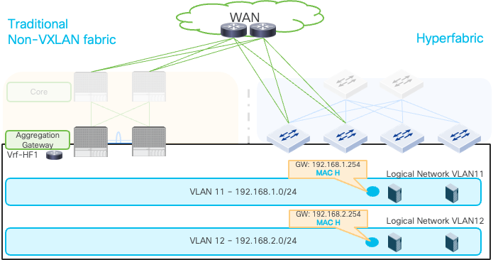
The figure below illustrates an example. The existing network on the left uses traditional core-aggregation-access topology where aggregation tier provides gateway by using HSRP or VRRP. The aggregation tier has multi-chassis port channel capability to connect access layer switches. This example uses the Cisco Nexus Hyperfabric leaf switches for Layer 2 and Layer 3 connections with the existing network similar to the main sections though the use of spine switches is also a valid option.

Extend Layer 2 connectivity from non-VXLAN fabric to Cisco Nexus Hyperfabric
Since general Layer 3 and Layer 2 considerations covered in the main sections are applicable to this migration example, this section will focus on gateway migration steps. See the main sections for general Layer 3 and Layer 2 connectivity considerations:
· Layer3 External Network Connectivity
After external Layer 3 connectivity is established and Layer 2 networks are extended across fabrics, the next step is to migrate the HSRP/VRRP based gateways from the existing network to the anycast gateways in Cisco Nexus Hyperfabric. Similar to the steps explained in Anycast Gateways with the Same MAC and IP Addresses, the key point is to use the same MAC addresses referred in the ARP tables in workloads.

Before migration: workloads have ARP tables using HSRP/VRRP gateways
In the main section, the following options were explained:
1. Change the anycast gateway MAC on Cisco Nexus Hyperfabric
2. Change the gateway MAC on the existing network
The first option was recommended because Cisco Nexus Hyperfabric being the new fabric added to the existing network. However, you likely need to change the gateway MAC on the existing network. It’s because the anycast gateway MAC on the Cisco Nexus Hyperfabric is a fabric-wide value whereas HSRP/VRRP gateway uses a unique MAC address for each group by default. Thus, this document explains the second option as an example.
| Note: · HSRPv1 uses 00:00:0C:07:AC:xx where xx is the HSRP group number. · HSRPv2 uses 00:00:0C:9F:Fx:xx where x:xx is the HSRP group number. · VRRP uses 00:00:5E:00:01:xx where xx is the VRID (Virtual Router Identifier). |
The deployment steps are as follows:
1. Change the gateway MAC (HSRP/VRRP virtual MAC) on the existing network to the anycast gateway MAC on the Cisco Nexus Hyperfabric. The example below uses MAC H as the new MAC address.
a. HSRP/VRRP is expected to send GARP to update its new MAC address.
2. Confirm the ARP table for the gateway IP on workloads is updated.

Change the anycast gateway MAC on the existing network
3. Configure the anycast gateway IP address for the logical network on Cisco Nexus Hyperfabric.
4. Remove the gateway on the existing network.

Add the anycast gateway IP address for the logical network and remove HSRP/VRRP gateway on the existing network
5. Migrate workloads to Cisco Nexus Hyperfabric.
After migrating workloads to Cisco Nexus Hyperfabric