New and Changed Information
The following table provides an overview of the significant changes to the organization and features in this guide from the release the guide was first published to the current release. The table does not provide an exhaustive list of all changes made to the guide.
|
Release |
New Feature or Update |
Where Documented |
|---|---|---|
|
4.2(2e) |
First release of this document. |
-- |
Summary
Prior to the Cisco Cloud Network Controller (CCNC) 26.0(2) release, all subnets belonging to one Azure VNet logical construct were associated to a single route table. This implied that communication from endpoints connected to the subnets part of that VNet would always use the same routing policy (that is, the same route entry in the single route table).
CCNC 26.0(2) introduces the per subnet route table feature that allows you to create an Azure VNet with multiple subnets, where each subnet can map to its own route table, or you can group subnets to share a specific route table.
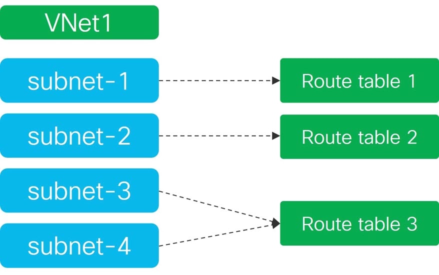
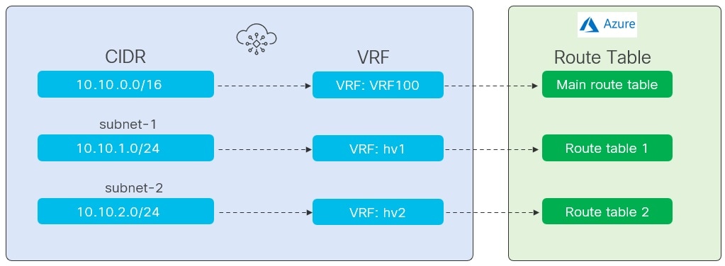
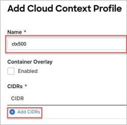
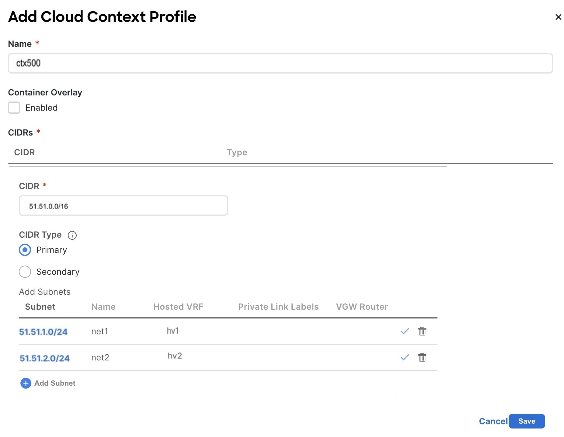
From a configuration point of view, the support of per subnet route table requires the configuration of multiple VRF instances. The main VRF instance is still mapped to a region and allows you to create a VNet (modeled in CCNC with a Cloud Context Profile object) with the associated the CIDR prefix. Additional VRFs instances (named as "Secondary VRFs") are then associated to one or more subnets defined in the VNet, carved out from the CIDR, to implement the logical mapping between subnets and route tables shown in figure below.
 Note |
This document interchangeably uses "route table" and "Azure user-defined routing (UDR)." |
This document shows how to use Cisco Nexus Dashboard Orchestrator (NDO) release 4.2(2) to drive the configuration of the per subnet route table functionality in one or more CCNC domains. The value proposition of this new functionality is highlighted by the use case described later in this chapter.
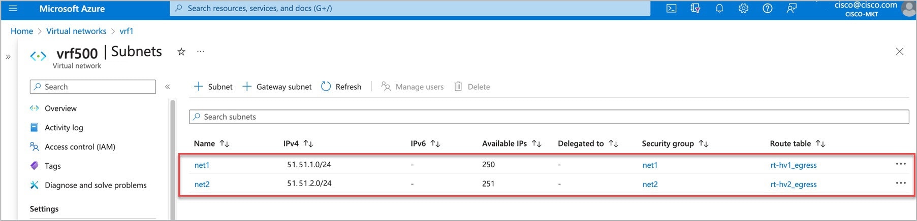
Variable Routing Policy Per Subnet
The benifit of this solution is to allow different routing treatments for different subnets in a VNet. It also opens the way for other useful features in the future. In the example below we see subnets belonging to the same VNet1 can have different routing policy based its own route table.
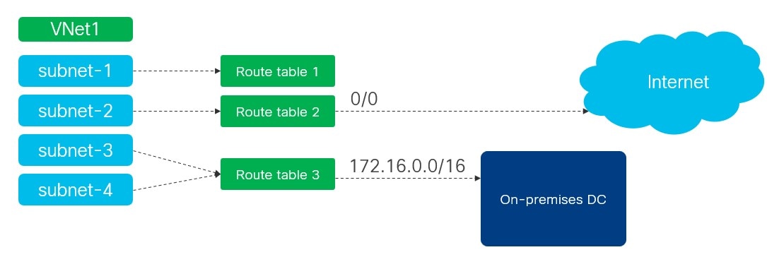
-
subnet-1cannot reach out to the internet. -
While
subnet-2can connect to the internet directly. -
Similarly, only
subnet-3andsubnet-4can reach out to the On-premises Data Center (DC).
Prerequisites
Before you follow the procedures described in this document, you must complete the following basic configuration tasks:
-
Deploy and have ready a Cisco Nexus Dashboard cluster.
This is described in detail in the Cisco Nexus Dashboard Deployment Guide for your release.
-
Onboard one or more cloud sites in the Cisco Nexus Dashboard.
This is described in detail in the Cisco Nexus Dashboard User Guide for your release.
-
Install and enable Cisco Nexus Dashboard Orchestrator, Release 4.2(2) or later.
This is described in detail in the Cisco Nexus Dashboard Orchestrator Deployment Guide for your release.
-
Enable the cloud sites for management in the orchestrator service and complete the basic infra configuration.
This is described in detail in the Cisco Nexus Dashboard Orchestrator Configuration Guide for ACI Fabrics for your release.
-
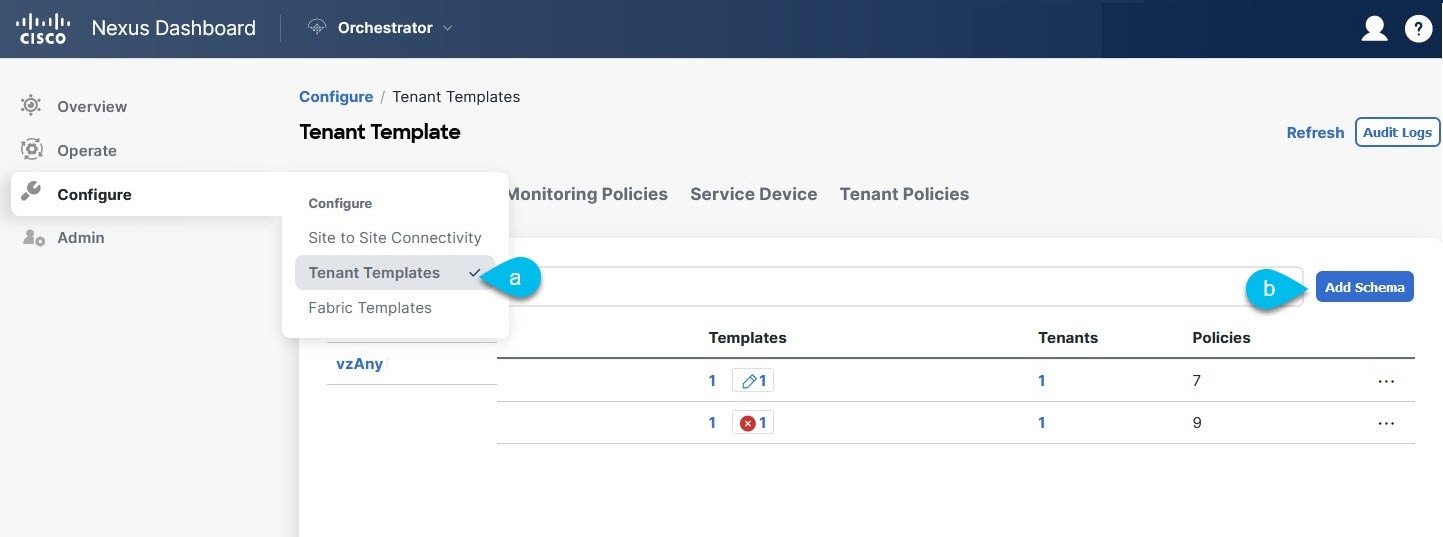
Add sites to the schema and provide configuration for the subnets.
Creating Schema and Templates
Before you begin
The following guidelines apply when creating the schemas and templates using the Cisco Nexus Dashboard Orchestrator:
-
You must have a user with either the
Power UserorSite Managerread/write role to create and manage tenants. -
You must have at least one available tenant that you want to incorporate into your site.
For more information, see Cisco Nexus Dashboard Orchestrator Configuration Guide for ACI Fabrics.
Procedure
|
Step 1 |
Log in to your Cisco Nexus Dashboard and open the Cisco Nexus Dashboard Orchestrator service. |
||
|
Step 2 |
Create a new schema.
|
||
|
Step 3 |
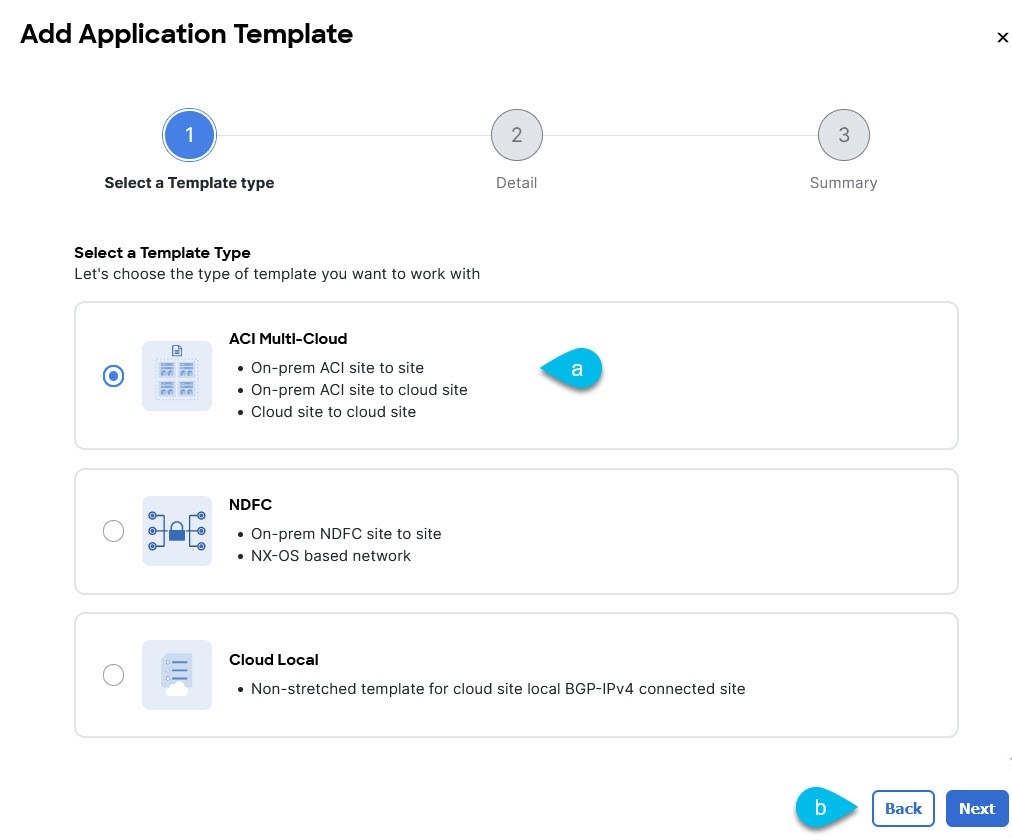
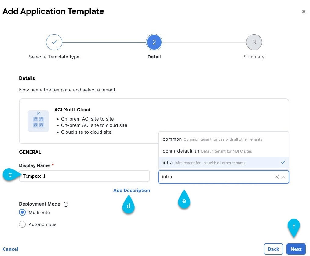
In the schema page, click Create New Template.
|
||
|
Step 4 |
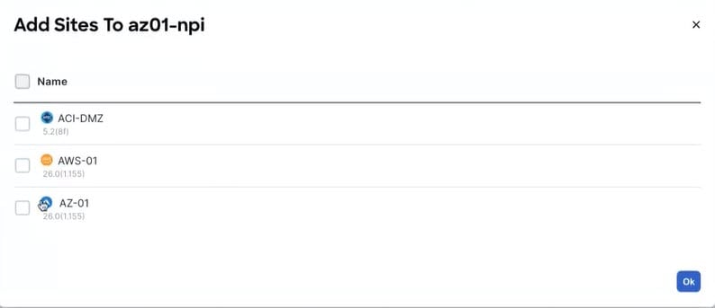
The next step is to assign the template to sites. Deploy fabric configuration by deploying one template at a time to one or more sites. You must associate the template with at least one site where you want to deploy the configuration.
|
Creating the VRF Instances
This section describes how to create the VRF instances.
Before you begin
Procedure
|
Step 1 |
Choose the schema and template where you want to create the VRF instance. |
|
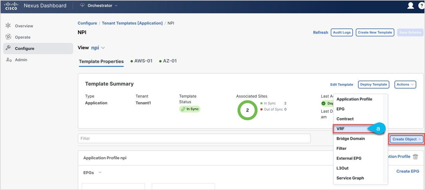
Step 2 |
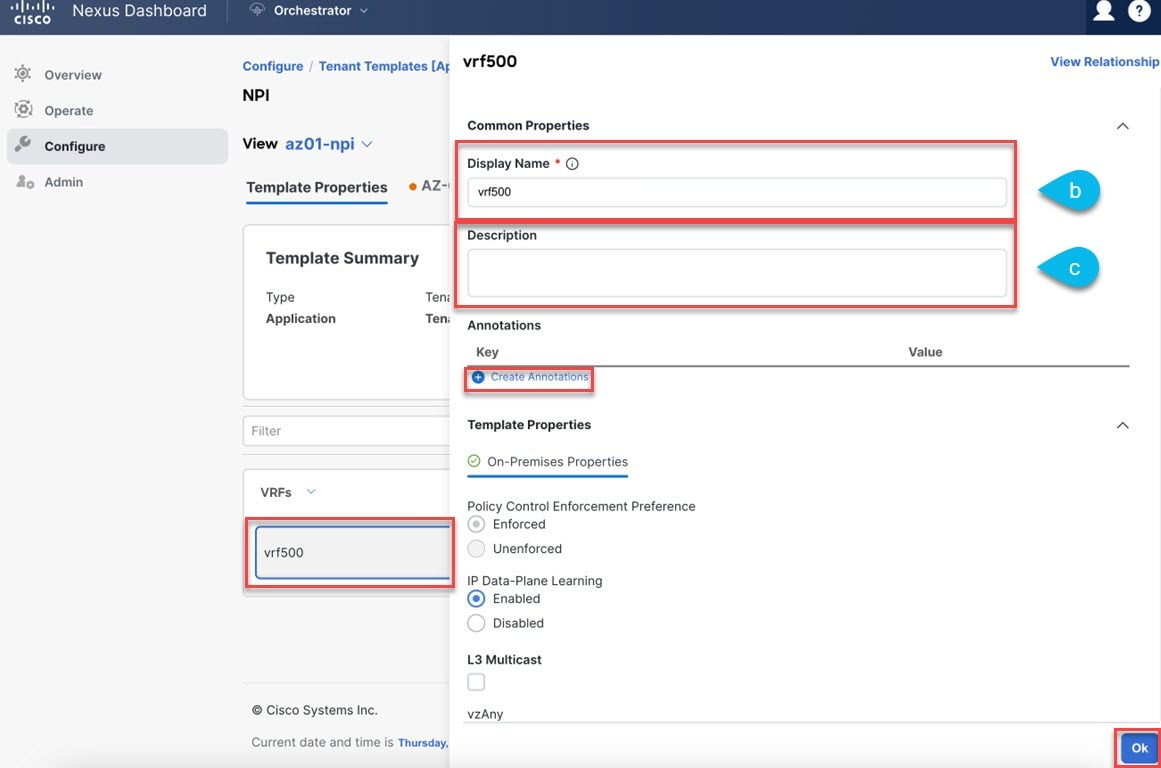
Create the VRF instance.
|
|
Step 3 |
(Optional) Add one or more Annotations. This allows you to add arbitrary |
What to do next
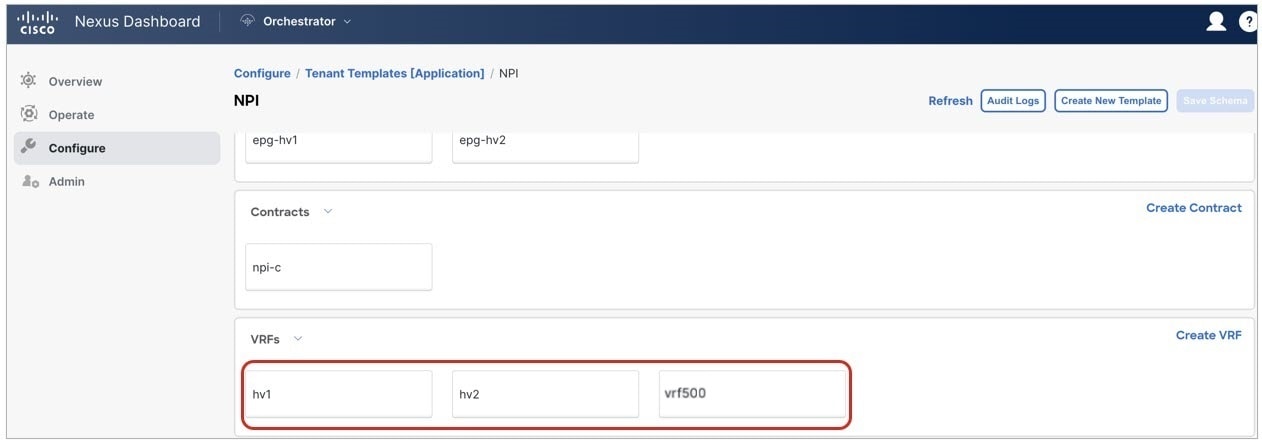
For our example use Step 1 - Step 3, to create two more secondary VRF instances (hv1 and hv2) under the same template as the parent VRF instance. Secondary VRF instances associate with each individual subnet (or with
a group of subnets) as described later in the example.
Configuring the VRF Instances
Before you begin
Procedure
|
Step 1 |
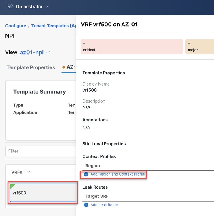
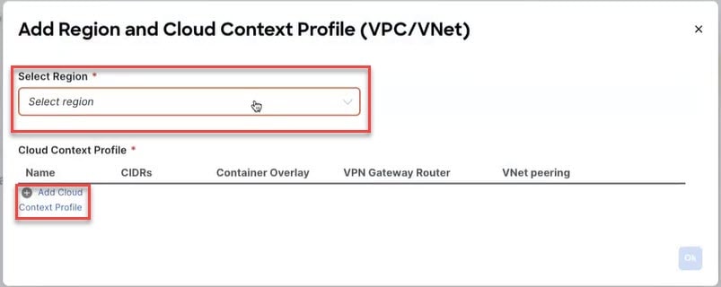
Select the site local template for the Azure site choose the parent VRF from the list of objects.
|
||||
|
Step 2 |
Put a check on VNet Peering box then choose Default from Hub Network drop-down list to enable VNet peering to the Infra VNet. 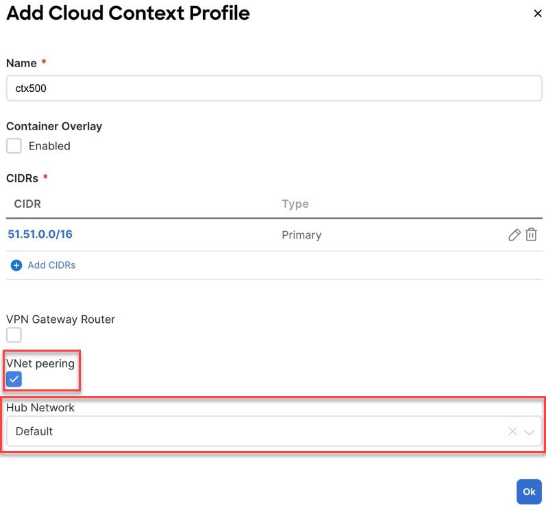
|
||||
|
Step 3 |
Click Ok to finish adding the cloud context profile to the VRF instance. |
||||
|
Step 4 |
Click on the Deploy Template button at the top-right corner of the screen to deploy the schema to the sites. You should see a message saying "Successfully Deployed" at this point. 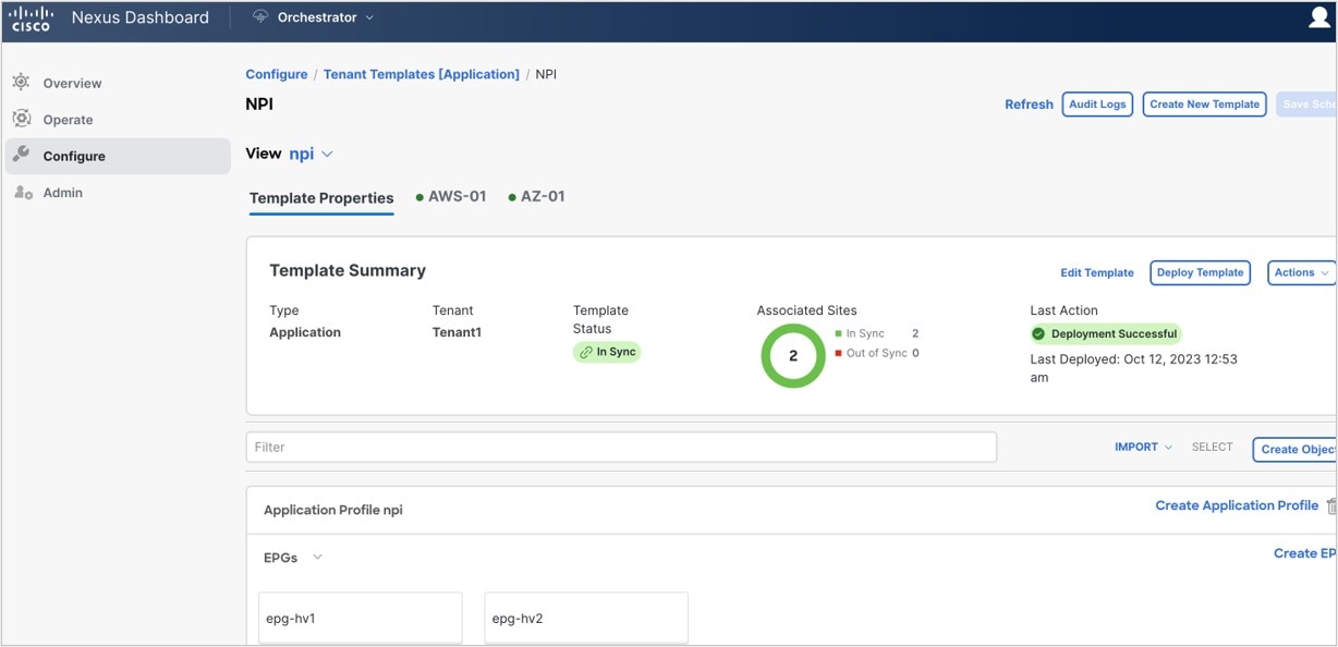
|
What to do next
 Feedback