The documentation set for this product strives to use bias-free language. For the purposes of this documentation set, bias-free is defined as language that does not imply discrimination based on age, disability, gender, racial identity, ethnic identity, sexual orientation, socioeconomic status, and intersectionality. Exceptions may be present in the documentation due to language that is hardcoded in the user interfaces of the product software, language used based on RFP documentation, or language that is used by a referenced third-party product. Learn more about how Cisco is using Inclusive Language.
Beginning with Release 6.1(1), a new node type ACI Border Gateways (ACI BGW) is available as a new feature on Cisco ACI.
Note
Procedures in this document describe how to configure ACI Border Gateways by using the GUI and REST API. You cannot configure
ACI Border Gateways through the NX-OS style CLI at this time.
About ACI Border Gateways
With the ACI border gateways solution you can now have a seamless extension of virtual routing and forwarding (VRF) instance
and bridge domains between Cisco ACI and the VXLAN EVPN domains. Additionally, from Cisco ACI release 6.1(4) it is also possible
to extend the ACI policy domain end-to-end to the VXLAN EVPN domain, allowing security enforcement between the security groups
that can be defined in each domain or even stretched across domains.
The ACI border gateway is the node that interacts with nodes within a site and with nodes that are external to the site. The
ACI border gateways together with the VXLAN EVPN border gateways, allow to build a multi-fabric domain and can be conceptualized
as multiple site-local EVPN control planes and IP forwarding domains interconnected via a single common EVPN control and forwarding
domain.
The Virtual eXtensible Local Area Network (VXLAN) Ethernet Virtual Private Network (EVPN) Border Gateways is a multi-site
solution that interconnects two or more BGP-based EVPN sites or fabrics (overlay domains) in a scalable fashion over an IP-only
network. It uses border gateways (BGWs) in anycast mode to interconnect a Cisco ACI side with one or more NX-OS sites and
allows new approaches to fabric scaling, compartmentalization, and using DCI. The border gateways provide the network control
boundary that is necessary for traffic enforcement and failure containment functionality.
A site-local EVPN domain consists of EVPN nodes with the same VXLAN site identifier. Border gateways on one hand are also
part of the site-specific EVPN domain and on the other hand a part of a common EVPN domain to interconnect with border gateways
from other sites. For a given site, these border gateways facilitate site-specific nodes to visualize all other sites to be
reachable only via them. This means:
Site-local bridging domains can be interconnected only via border gateways with bridging domains from other sites.
Site-local routing domains can be interconnected only via border gateways with routing domains from other sites.
Understanding ACI Implementation of ACI Border Gateways
ACI implements ACI border gateways by using the following ACI components that have been introduced in Cisco APIC.
VXLAN Site ID
Starting from Cisco ACI release 6.1(2), you must configure a site ID. You will not be able to configure the border gateway
set policy if you do not have this site ID.
Refer to VXLAN Site ID to know more about creating a site ID for your VXLAN site.
Note
If you have already configured the ACI Border Gateway feature for Cisco APIC 6.1(1), and upgrade to Cisco APIC 6.1(2) without
creating a VXLAN site ID a fault is generated for all the stretched VRFs and bridge domains.
ACI Border Gateways Set
These are a set of border gateway nodes that are used to connect to the remote VXLAN EVPN fabrics. These border gateway nodes
could either be part of an ACI Pod or be deployed across different Pods when the ACI fabric is a multi-pod fabric. All border
gateways within a Pod are assigned the same unique external anycast TEP per Pod to attract traffic for endpoints within this
Pod from the remote fabric.
Cisco APIC assigns a unique internal anycast TEP for a border gateway set, which is common for all the border gateway nodes
that are deployed across all the Pods (hence, belonging to the same border gateway set). You can configure only one border
gateway set.
In the remote fabric configuration, you will specify the remote site’s loopback IP address on the remote border gateway, which
is used to establish the MP-BGP EVPN adjacency. You can associate multiple VXLAN remote fabric policies, one for each remote
site, with the same border gateway set.
VXLAN Infra L3Out defines the group of border gateway nodes and the associated interfaces for the underlay connectivity with
the external Inter-Site Network infrastructure (ISN). Only eBGP is supported as the underlay protocol between the Cisco ACI
border gateway nodes and the directly connected ISN devices. Optionally, BFD can be enabled between the border gateway nodes
and the ISN devices to protect against specific failure scenarios where traffic forwarding is impacted without a link-down
event on the point-to-point interfaces between devices.
In Cisco ACI release 6.1(1), to stretch a user VRF, you configure a user VXLAN L3Out that is associated to a border gateway
set. You also associate all the remote fabrics to this L3Out to stretch the VRF to the corresponding sites. The VRF that is
stretched towards the VXLAN fabric can only be in an unenforced mode.
Starting from Cisco ACI release 6.1(4), a normalization function is introduced on ACI border gateways, which allows to translate
the VNID locally assigned by Cisco APIC to a VRF in the local ACI fabric to the VNID assigned to the same VRF when stretched
to the VXLAN EVPN domain.
In Cisco ACI release 6.1(1), use the VXLAN bridge domain stretch to stretch a bridge domain to a remote VXLAN EVPN fabric.
You can associate multiple remote fabrics to stretch the bridge domain to the corresponding remote VXLAN EVPN sites
Starting from Cisco ACI release 6.1(4), a normalization function is introduced on ACI border gateways, which allows to translate
the VNID locally assigned by APIC to a bridge domain in the local ACI fabric to the VNID assigned to the same bridge domain
when stretched to the VXLAN EVPN domain.
The Cisco ACI Quality of Service (QoS) feature allows you to classify the network traffic in your fabric and then to prioritize
and police the traffic flow to help avoid congestion in your network. When traffic is classified within the fabric, it is
assigned a QoS Priority Level, which is then used throughout the fabric to provide the most desirable flow of packets through
the network.
You can use custom VXLAN QoS policies to define how traffic coming from the VXLAN EVPN domain is prioritized within the ACI
fabric. You can also use these policies to re-mark the traffic destined to the VXLAN EVPN domain when it leaves the ACI fabric
via the ACI border gateway. The custom QoS policy is divided into an ingress QoS policy and an egress QoS policy.
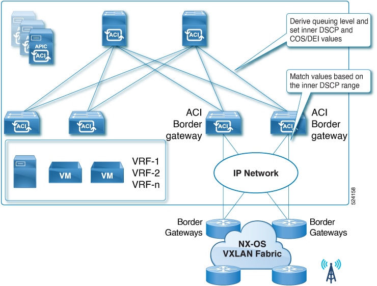
Ingress rules: As part of the ingress VXLAN policy, you can define how the traffic that originated from the VXLAN EVPN domain and received
on the ACI border gateways are treated inside the fabric (queuing priority). You can match the inner DSCP value of incoming
VXLAN traffic originated from the remote VXLAN EVPN domain and consequently set the QoS priority and also set the inner CoS
and DSCP values for that traffic inside the ACI fabric.
Figure 1. Example showing the ingress VXLAN QoS policy.
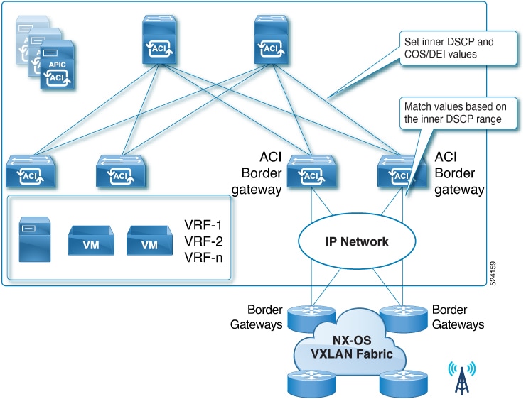
Egress rules: As part of the egress VXLAN policy, you can control the values that needs to be marked in the outer DSCP and CoS fields.
The inner DSCP value of the iVXLAN encapsulated traffic originated from the ACI leaf nodes will be matched on the ACI border
gateways. Based on this match, the outer CoS and DSCP values of the VXLAN traffic sent to the remote VXLAN EVPN domain will
be set. If you do not specify any values, the outer DSCP and CoS values are set to the default value of zero.
Figure 2. Example showing the egress VXLAN QoS policy.
VRF in Enforced Mode
Starting with Cisco ACI release 6.1(2), the VRFs can be configured in enforced mode. The endpoints and prefixes that are advertised
from the remote VXLAN EVPN fabrics can be classified into endpoint groups that are represented through Endpoint Security Group
objects (ESG). To enable communication between endpoints that belong to different ESGs, you need to setup policies represented
through contracts.
The following sections discuss the various building blocks that are required to configure a VRF in enforced mode.
Starting from Cisco ACI release 6.1(4), the remote SGT values are carried across domains, On the Cisco ACI border gateway,
you do not need to classify the endpoints and the external prefixes that are advertised from the remote VXLAN EVPN fabrics.
Endpoint Security Groups
Endpoint Security Groups (ESGs) are a network security component in Cisco ACI. It is a logical entity that contains a collection
of physical or virtual network endpoints. An ESG is a security construct that has certain match criteria to define which endpoint
belongs to the ESG and uses contracts or policies to define the security criteria. The administrator uses a contract to select
the types of traffic that can pass between ESGs, including the protocols and ports that are allowed.
Contracts
Contracts are the Cisco ACI equivalent of access control lists (ACLs). Endpoint Security Groups (ESGs) can only communicate
with other ESGs according to the contract rules. You can use a contract to select the types of traffic that can pass between
ESGs, including the protocols and ports allowed. An ESG can be a provider, consumer, or both provider and consumer of a contract,
and can consume multiple contracts simultaneously. ESGs can also be part of a preferred group so that multiple ESGs can talk
freely with other ESGs that are part of the preferred group.
The match criteria are called the ESG selectors that are based on attributes such as an IPv4 or IPv6 address spanning across
bridge domains in the associated VRF instance, or a tag associated to endpoint MAC address. To enable communication between
endpoints that belong to different ESGs, you need to configure contracts between the ESGs. For the communication with devices
outside of the Cisco ACI fabric, you need to configure a contract between the L3Out external EPG (l3extInstP) and the ESG. You can classify endpoints connected inside the ACI fabric and external network prefixes learned through L3Out
connections by using one of the selectors, such as EPG selector, IP subnet selector, Tag selector, and so on.
For more information on the existing selectors that are available on Cisco APIC, refer to Endpoint Security Groups section of the Cisco APIC Security Configuration Guide, Release 6.1(x).
Cisco ACI to Policy-Unaware Remote VXLAN EVPN Use Case
Cisco ACI classifies the incoming traffic to an ESG based on the different selectors that are configured. These selectors
are configured under each ESG with a variety of matching criteria.
Starting with Cisco ACI release 6.1(2), two new selectors have been added to classify endpoints and external destinations
learned from remote VXLAN EVPN fabrics.
On Cisco APIC release 6.1(2) and 6.1(3), this was known as VXLAN External Subnet Selector for ACI VXLAN Border Gateway (BGW).
Starting with Cisco APIC release 6.1(4), this is enhanced as a generic External Subnet Selector that can be used for regular
L3Out subnets.
This selector matches EVPN Type 5 routes that are received on ACI border gateway nodes from another fabric. The match occurs
in the Longest Prefix Match (LPM) manner.
Starting with 6.1(4), this selector can also match external prefixes learned through regular L3Outs without the border gateway.
This can be used as a replacement of L3Out external subnets with the "External Subnets for the External EPG" scope under L3Out
external EPGs.
The "shared" flag under External Subnet Selector is used to leak the mapping of ESG and the prefix to the other VRFs connected
through contracts. This is equivalent to the "Shared Import Security Subnet" scope in the case of L3Out exteranl subnet. Note
that this flag leaks only the security information and the actual route leaking must be separately configured at the VRF level.
Note
The default route (0.0.0.0/0 or 0::0/0) cannot be configured as an External Subnet Selector. As a workaround, 0.0.0.0/1 and 128.0.0.0/1 or 0::0/1 and 8000::/1 can be used to match everything.
Starting with Cisco ACI 6.1(5), the above limitation is not applicable. You can use the default route (0.0.0.0/0 or 0::0/0) to configure an External Subnet Selector.
Use this selector to classify all the L2 MAC addresses that are associated to the specific stretched bridge domain learned
from the remote VXLAN fabrics into a corresponding ESG. This selector can be configured only for bridge domains that are VXLAN
stretched. The endpoints from all the remote fabrics belonging to this bridge domain are classified as part of the same ESG.
For policy-unaware VXLAN EVPN fabrics, existing IP subnet selectors can be used for the classification of endpoints (connected
hosts) part of IP subnets that are only locally defined in the remote VXLAN EVPN fabrics (i.e. not stretched across ACI and
VXLAN EVPN domains).
Note
This is different from the VXLAN External Subnet selectors, that is, only the exact matching prefixes can be used to classify
remote DC subnets. A prefix that covers a super-net will not be feasible.
You can classify specific L2 MAC addresses and specific L3 IP addresses from the remote VXLAN fabric into an ESG by using
the existing MAC tag selector or the IP tag selector.
Cisco ACI to Policy-Aware VXLAN EVPN Use Case (Starting from Cisco ACI release 6.1(4))
In this first use case, supported from ACI release 6.1(4) and NX-OS release 10.5(3), the Cisco ACI domain is connected to
a policy-aware remote VXLAN EVPN domain. The EVPN control plane between the ACI border gateways and the remote VXLAN EVPN
border gateways has been enhanced to carry the tags identifying the security groups defined in each domain. This implies that
the classification for both internal and external resources is performed independently inside each domain.
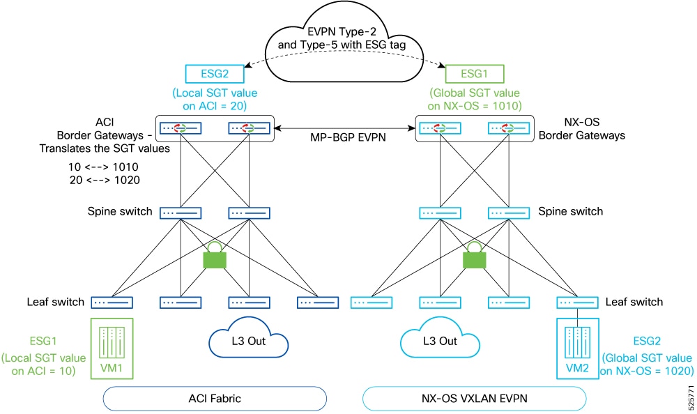
Figure 4. Cisco ACI to Policy-Aware VXLAN EVPN options
Remote Security Group Tag (SGT)
A Security Group Tag (SGT) is the identifier of a logical entity (Security Group) that contains a collection of physical or
virtual network endpoints and external resources that are classified based on attributes or selectors. Starting with ACI release
6.1(4), a new capability is introduced of carrying the SGT values via the EVPN control plane between the ACI and the VXLAN
EVPN domains. With policy-aware remote EVPN fabrics, this remote SGT is a required configuration.
This is a required configuration when the remote VXLAN EVPN domain is policy-aware and therefore the EVPN control plane between
ACI border gateways and remote VXLAN EVPN border gateways allows to carry the policy information. A remote SGT value must
be associated on Cisco APIC to every ESG that is locally defined in the Cisco ACI fabric, as it represents the SGT used for
identifying those security groups in the remote VXLAN EVPN domain.
To understand the usage of the remote security group tags, let's consider the scenario shown in previous figure Cisco ACI to Policy-Aware VXLAN EVPN options. ESG1 is locally defined in the ACI fabric to classify local internal and/or external resources and gets assigned an SGT
value by APIC (10 in this specific example), which is locally significant in the ACI domain. When the ACI border gateways
advertise the prefixes as part of ESG1 towards the remote VXLAN EVPN domain, they first translate the local value 10 to a globally significant remote SGT value (1010) identifying ESG1 in the remote VXLAN EVPN domain. Similarly, when the ESG2
group is defined in the VXLAN EVPN domain to classify local internal and/or external resources, a global SGT value (1020)
is assigned to it. This value is used by the VXLAN EVPN border gateways to advertise ESG2 prefixes toward the ACI domain.
When the ACI border gateways receive them, they translate that remote SGT value to a local SGT value (20) identifying the
ESG2 group inside the ACI domain. A global security policy will then need to be provisioned to control the communication between
ESG1 and ESG2.
Note
While the example shown in the figure Cisco ACI to Policy-Aware VXLAN EVPN options refers to a scenario where two different security groups are defined inside each domain, it is also possible to functionally
stretch a security group across the two domains. In such a case, the same ESG name would be used to identify such a group
and classify the resources inside Cisco ACI and VXLAN EVPN domains. and a single translation between the ACI local SGT and
remote SGT value would be performed by the ACI border gateways.
For a remote EVPN fabric, the SGT tags that are not mapped to any ESG on ACI fabric, are classified with the value 12, which is the default drop-class. This tag is applicable for both endpoints and prefixes from the remote EVPN fabric. For
endpoints and prefixes that belong to ESGs without a remote SGT, ACI advertises the tag with a tag value of 0 to the remote
EVPN fabric. 0 is the default value for the drop SGT tag in the NX-OS based EVPN fabric.
VXLAN EVPN Route-Maps
Starting with Cisco ACI release 6.1(2), the ACI Border Gateway feature supports VRF level route-maps that can be configured
on the stretched VRFs. These route-maps are applicable for all the remote fabrics that are associated to the border gateway
set. The route-map set rules are configured with the route control profile policies and the action rule profiles. You can
specify the Permit or Deny statements based on the match criteria.
You can control the routes that can be imported or exported to the remote EVPN fabrics. Inbound route-maps are applied on
Type-5 and the IP portion of the Type-2 routes. Type 2 MAC routes are not impacted and are imported irrespective of the IP
import status.
Outbound route-maps are only applied to Type-5 routes.
This is an optional configuration. If you do not configure import route-maps, all the routes received from remote VXLAN EVPN
fabrics are accepted. If you do not configure export route-maps, all the local bridge domain subnets and external routes are
advertised to the remote VXLAN EVPN fabrics. For this you must ensure that you have enabled Advertised Externally flag on the bridge domain subnets.
Following are the list of match and set clauses that are supported by both the inbound route-map and the outbound route-map:
Supported Match Clauses
IP Prefix List
AS-Path
Community
Extended Community (match on color extended community is not supported)
Regex Community
Regex Extended Community
Supported Set Clauses
Community
Extended Community
Weight
Preference
Metric
Switched Port Analyzer (SPAN) on Cisco ACI Border Gateway
Switch port Analyzer (SPAN) is an efficient, high performance traffic monitoring system. It directs or mirrors traffic from
a source port or VLAN to a destination port. Encapsulated remote SPAN (ERSPAN) brings generic routing encapsulation (GRE)
for all captured traffic and allows it to be extended across Layer 3 domains.
The following SPAN features are supported on the ACI border gateway:
The local span must be configured on the border gateway, where you configure the source as the infra L3Out interface and destination
as another port on the border gateway.
The ERSPAN monitoring session for an infra L3Out interface supports the monitoring of both ingress traffic and egress traffic.
There is no filtering support as the monitoring works only on the port level.
The ERSPAN monitoring session for fabric interface on a border gateway supports the monitoring of both ingress traffic and
egress traffic. There is no filtering support as the monitoring works only on the port level.
Support for on-drop SPAN is enabled.
Starting from Cisco ACI release 6.1(4), support for ERSPAN is enabled, where the destination ERSPAN is deployed on the remote
VXLAN fabric. The local ERSPAN is available on Cisco ACI and the destination ERSPAN is available on the remote VXLAN fabric.
The following ERSPAN guidelines are applicable on the ERSPAN session for the ACI border gateway:
The ERSPAN destination IP must be configured from the Cisco ACI bridge domain EPG. This maps the connected endpoints in the
remote VXLAN EVPN fabric.
The ERSPAN destination IP behind the remote VXLAN fabric L3Out, where the destination IP is not accessible via the prefix
subnets of the remote VXLAN fabric, is not supported.
The ESG EP prefix cannot be configured as the ERSPAN destination.
The ERSPAN source IP needs to be present on the remote VXLAN border gateway with a tag.
A contract must exist between the ERSPAN source IP and ERSPAN destination IP on the remote VXLAN site to ensure a smooth flow
of ERSPAN traffic to the VXLAN prefix destination.
To ensure the use the EPG bridge domain as the ERSPAN destination, a bridge domain must be stretched from the remote VXLAN
fabric to the ACI fabric.
Ensure that the EP move completes successfully before you check the ERSPAN traffic.
Migrate Multiple ACI Fabrics with Existing L3Out Connectivity to an ACI Border Gateway
Starting with Cisco ACI release 6.1(5), you can interconnect ACI sites using the ACI VXLAN Border Gateway (BGW) path. If your
environment already uses L3Out connections for inter-fabric layer 3 connectivity, you can migrate to the ACI VXLAN border
gateway interconnect.
When configuring these connections, ensure that each ACI site has a unique VXLAN site ID and a unique ACI multi-site ID. In
addition, configure identical remote L3VNI and remote L2VNI values on all ACI sites for each VRF and bridge domain (BD) when
extending connectivity. Cisco ACI 6.1(5) only supports eBGP L3Out connectivity between ACI sites.
Note
You may experience minor traffic loss during the migration.
Follow these steps to migrate multiple ACI fabrics with existing L3Out connectivity to the ACI VXLAN border gateway.
Set up the border gateway and configure the VXLAN infrastructure L3Out. For detailed instructions on deploying the border
gateway and configuring VXLAN infra L3Out, refer to the sections below.
Migrate your existing EPGs and external EPGs—excluding site-to-site L3Out external EPGs—to Endpoint Security Groups (ESGs)
that you plan to use with the VXLAN border gateway. When creating each ESG, be sure to assign a normalized pcTag value. For
more information on configuring the pctag, refer to Configuring a Remote Security Group Tag Under a Endpoint Security Group
Note
You must set the normalized pctag on both sites, and the values must match on each site.
Stretch the tenant VRFs that you plan to migrate between ACI sites, making sure to specify the normalized VNI for each VRF.
For detailed instructions, see Configuring a VXLAN VRF Stretch Using the GUI.
When a VRF is stretched across both the L3Out and the ACI Border Gateway (BGW) path, the same route may be learned from both
connections. If you do not define a specific route policy, the BGP best path selection algorithm will determine which path
is preferred.
When migrating from an L3Out interconnect to the ACI Border Gateway (BGW) interconnect path across ACI sites, you must configure
a route policy to ensure that the BGW path is preferred on all nodes. You can accomplish this by applying L3Out peer inbound
route maps on the border leafs that connect the ACI sites.
After completing the VRF stretch, remote sites will advertise prefixes through VXLAN EVPN. The local site will then have two
available paths: one via L3Out and one through the VXLAN BGW. To prefer the VXLAN path, apply route maps under the site-to-site
L3Out and assign a lower local preference to prefixes received through this connection. Ensure that the route map direction
is set to import.
Understanding the ACI Border Gateways Deployment
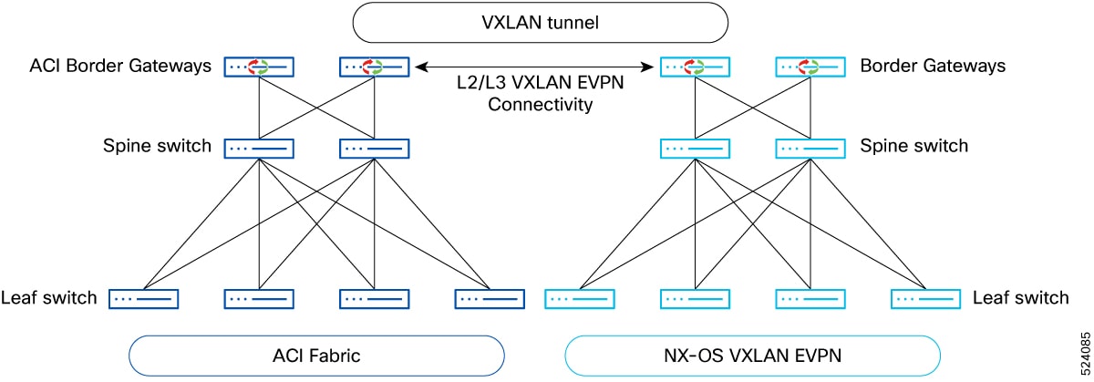
The following figure shows the deployment for the ACI Border Gateways in Cisco ACI.
Figure 5. Deployment of the ACI Border Gateways in Cisco ACI
VXLAN is used as the overlay technology to encapsulate the data packets and tunnel the traffic over the Layer 3 Inter-Site
Notwork (ISN).
The VXLAN handoff is performed by the Border Gateway nodes, which stitch VXLAN tunnels used inside each specific ACI and VXLAN
EVPN domain with VXLAN tunnels used across domains.
The L2/L3 VXLAN connectivity between Cisco ACI Pods that are part of the same fabric continues to be achieved via the spine-to-spine
data path, through the IPN.
Cisco ACI border gateways must be locally present in each Pod. If the ACI border gateways are not locally present in the Pod,
it will not be possible for endpoints belonging to a specific Pod to communicate with the remote VXLAN EVPN domain via the
ACI border gateways that are deployed in a separate Pod.
Figure 6. Cisco ACI Border Gateway in a Pod
For each bridge domain extended across domains, a specific Cisco ACI border gateway is elected as the designated forwarder
across all the border gateway in all the Pods. The designated forwarder border gateway will then send and receive flood traffic
for that BD with the remote VXLAN EVPN domain.
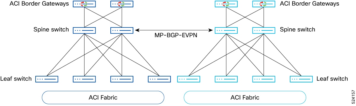
Prior to Cisco ACI release 6.1(5), there was no support to establish Layer-2 and/or Layer-3 connectivity between ACI fabrics
using the border gateway nodes deployed in each fabric. Cisco ACI border gateways can only be used to extend connectivity
and policy to the remote VXLAN EVPN domain. The only supported way to extend connectivity and policy between ACI fabrics is
via the ACI Multi-Site architecture, leveraging inter-site connectivity through the spine nodes, as shown in figure below.
Starting with Cisco ACI release 6.1(5), you can establish Layer -2 and/or Layer-3 connectivity between ACI fabrics using the
border gateway nodes deployed in each fabric.
Figure 7. Layer-2 / Layer-3 connectivity Between ACI Fabrics Using the Border Gateway Nodes for releases prior to Cisco ACI 6.1(5)
Guidelines and Limitations for ACI Border Gateways
Following are the guidelines and limitations for the ACI border gateways feature.
Hardware support for ACI border gateways are Nexus 9000 platforms from FX models and above, as long as they support 32GB of
RAM (Hence, FX2 platforms are not supported).
Dedicated leaf nodes for the ACI border gateway functionality. Coexistence with border leaf functions (Tenant L3Outs) in a
border gateway is planned for a future release.
L2 Multicast traffic forwarded as BUM.
In Cisco APIC 6.1(1), an unenforced VRF configuration is required on the Cisco ACI fabric for VRFs that need to be stretched.
This limitation is only applicable in Cisco APIC 6.1(1).
Starting with Cisco APIC 6.1(2), you can configure stretched VRFs in an enforced mode on the Cisco ACI fabric and use ESGs
to apply the security policy with the internal/external resources in the VXLAN EVPN domain.
Support for a single ACI fabric (can be Multi-Pod).
Starting with Cisco release 6.1(5), multiple independent Cisco ACI fabrics can communicate with each other through a border
gateway.
Starting with Cisco APIC 6.1(2), the ACI fabric needs to specify a unique site ID for the EVPN domain, which is defined by
vxlanSiteId configuration.
Prior to Cisco ACI release 6.1(4), VNIs for a bridge domain or VRF needs to be symmetrical across Cisco ACI and the NX-OS
fabric. As you cannot control the VNIDs that are assigned by Cisco APIC to the VRFs or bridge domains, initial support is
only available for the VRFs or bridge domains that are stretched from Cisco ACI to VXLAN EVPN domain to ensure that matching
VNIDs can be configured on the remote VXLAN EVPN fabrics.
Beginning with Cisco ACI release 6.1(4), you can specify a normalized VNI, which would be the VNI used as part of the VRF
or bridge domain stretch used on the remote EVPN fabric.
When you use the same IPN/ISN device for both ACI Multi-Pod/Multi-Site and VXLAN inter-site, we recommend that you isolate
the Multi-Pod/Multi-Site and the VXLAN inter-site networks in different VRFs.
In Cisco APIC 6.1(1), VRFs that are stretched between the ACI and VXLAN EVPN domains must be configured with the non-VLAN
based L3 VNI configuration in the VXLAN EVPN fabrics. This is referred as new way of VRF configuration.
Starting with Cisco APIC 6.1(2), the NX-OS L3VNI configuration can either be configured with non-VLAN based or VLAN based
L3 VNI configuration.
The ACI border gateway feature requires that all nodes in the fabric are running the same version to be running on Cisco 6.1(4).
You must select the same set of spine nodes as the internal route-reflector and the mpod-spine in the given Pod.
Back-to-back connections between the Cisco ACI VXLAN border gateway and the NX-OS border gateway are not supported.
Starting from Cisco APIC 6.1(4), all endpoints that belong to the bridge domain in the VRF are advertised only if the bridge
domain is stretched. If you want all endpoints to be advertised you must stretch all the bridge domains within the VRF.
Starting with Cisco APIC release 6.1(4), all policy information for endpoints and routes exchanged between an ACI site and
a remote EVPN fabric is managed by the control plane. Endpoints are advertised to the remote fabric only when their bridge
domains are stretched within the ACI fabric. Therefore, for any stretched VRF, stretching the bridge domain is required to
ensure end-to-end policy enforcement.
When you upgrade from Cisco APIC 6.1(1) to Cisco APIC 6.1(4), ensure that you first configure the site ID, clear all the existing
faults from the previous Cisco APIC versions, and wait for the BGP to converge before you proceed to upgrade.
When you have a load balancer SNAT and when the service bridge domain is not stretched to a border gateway on the Cisco ACI
fabric you must ensure that the following conditions are applicable for the service redirection with the load balancer:
Ensure that the LB Servers are located on the Cisco ACI site.
Ensure that the service EPG is uplifted to service ESG and that you create a contract between the internal leg of the ESG
and the provider SGT on the NX-OS site.
Beginning with Cisco ACI release 6.1(5), if a common DPTEP IP address is configured across VXLAN or ACI sites and you change
the DPTEP IP address on one of the sites, traffic loss occurs. To restore traffic, flap the BGP EVPN session between the sites.
Starting with Cisco APIC release 6.1(5), each ACI fabric must be assigned a unique site ID across the entire domain using
the vxlanSiteId configuration. If a common site ID exists across VXLAN or ACI sites and you change the site ID, traffic loss will occur.
To restore traffic, change the site ID to a unique value for each site within the domain.
The following features are not supported in this release:
SPAN with ACL
ERSPAN destination can be an endpoint or prefix that is local to the ACI fabric.
Multi-Site EVPN can be deployed only in full-mesh mode. To integrate with Cisco ACI, it can only done in full-mesh EVPN mode
between Cisco ACI and the NX-OS fabric. The route-server model is not supported.
The VRF or bridge domains stretched to VXLAN sites should not be deployed on the ACI remote leaf switches.
Cisco ACI fabric with border gateways can be part of the ACI multi-site domain. But the VRFs or bridge domains that are stretched
towards the VXLAN EVPN domain cannot be stretched to other ACI multi-site fabrics and vice-versa.
Between NX-OS and ACI fabrics, extension of bridge domains that are associated to EPGs with micro segmentation is not supported.
In Cisco APIC 6.1(1), there is no support for ingress or egress route-maps in EVPN peers in ACI. Any route-filtering can be
done only on the remote NX-OS fabric BGW.
Starting from Cisco APIC 6.1(2), support has been introduced for route-maps. You can control the routes that can be imported
from the remote EVPN fabrics or exported to the remote EVPN fabrics..
Inbound route-maps are applied on Type-5 and the IP portion of the Type-2 routes. Type 2 MAC routes are not impacted and are
imported irrespective of the IP import status.
Outbound route-maps are only applied to Type-5 routes.
IGMP snooping and L3 Multicast traffic is not supported across domains.
Inter-VRFs traffic flows (shared services) is not supported on releases prior to Cisco ACI 6.1(4).
Starting from Cisco APIC 6.1(4), inter-VRF traffic flows (shared services) is supported but all the VRFs that are part of
the shared services must be deployed on ACI border gateway and the remote EVPN border gateway.
The leaked route should not be advertised to its peers from the VRF
If a VXLAN EVPN domain is policy unaware, the service redirection (PBR) for traffic flows between domains is only supported
to service devices deployed in L3 (Go-To) mode and connected to the Cisco ACI fabric.
Starting from Cisco APIC 6.1(4), when an ACI fabric interconnects with a policy-aware remote VXLAN fabric, any policy or class
details received from the remote VXLAN fabric are ignored by the ACI border gateway nodes, if you are interacting with the
remote EVPN NX-OS 10.5(3) version fabric. Also, the ACI fabric does not advertise its policy or class information to the remote
VXLAN fabric.
Cisco ACI 6.1(4) and NX-OS 10.5(3) version is the minimum viable combination for interoperability between policy aware sites.
If you have a version prior to NX-OS 10.5(3) you can only connect with Cisco ACI in policy unaware interop mode.
The following restrictions are applicable for the external prefixes in policy aware interoperability sites:
When you configure the external subnet selectors, you need to ensure that the subnet selector is always a super net of the
prefixes that it learns from its L3Out peer. If the subnet configuration is a subnet of the prefix it is not classified as
endpoint of the prefix.
For example, if you have a learned ACI external route of 50.1.0.0/16 and the ESG prefix selector configured to 50.1.1.0/24, Cico ACI advertises the external route 50.1.0.0/16 as the Type-5 route with the default ESG tag of 0.
When you configure external prefixes you cannot configure overlapping prefix selectors. For example, if you have two ESGs,
where ESG-1 has a prefix selector with 50.1.1.0/24 as the external route the second ESG-2 with 50.1.0.0/16 as the external route, then Cisco ACI can either choose ESG1 or ESG2, as this classification is not deterministic.
When you configure the VRF route leaking for a VXLAN stretched VRF, you must use the leak internal prefix option to leak the
routes.
For more information on how to leak internal prefixes, see the Configuring Route Leaking of Internal Prefixes Using the GUI
section in the Cisco APIC Security Configuration Guide.
If you have multiple bridge domains within the same VRF stretched across ACI sites and use border gateways with remote VNI
configuration, changing a bridge domain's remote VNI to match the remote VNI used for the VRF in another site—and then reverting
it—can cause endpoints from one bridge domain to be missing in COOP.
To restore the missing endpoints in COOP, reset (flap) the EVPN sessions between the border gateways at each ACI site. This
action repopulates the missing endpoint information in COOP.
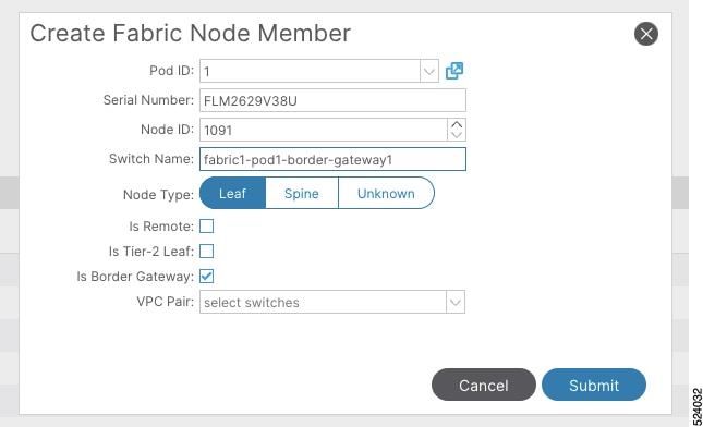
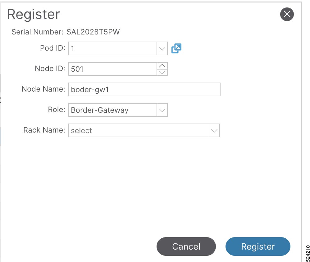
Discovering ACI Border Gateways
To register a node type as a border-gateway, complete the following steps:
Before you begin
You must register each leaf node with the node type border-gateway for it to be displayed as an ACI border gateway.
Note
You cannot register a spine with the node type border-gateway. The discovery will be blocked.
Procedure
Step 1
To pre-configure the node registration policy, if you are already aware of the serial number:
The VXLAN infra L3Out configuration allows you to select the ACI Border Gateway nodes and interfaces to establish EBGP underlay
adjacencies with the network devices part of the inter-site network infrastructure (ISN). This is required to exchange underlay
reachability information with the remote NX-OS Border Gateways and establish the overlay EVPN adjacencies with them.
You will configure the following pieces when configuring the VXLAN infra L3Out:
Only border gateways are allowed to be configured as nodes in the VXLAN infra L3Out.
Each VXLAN infra L3Out must have border gateways from multiple pods that are part of the same ACI multi-pod fabric.
The border gateway can either be configured in a single VXLAN infra L3Out or multiple VXLAN infra L3Outs based on your QoS
policy.
When you configure a node profile, you can configure the Router ID and the loopback interface underneath the node. The IP
address assigned to the loopback interface on the border gateway is used to establish the BGP EVPN control plane peering with
the NX-OS border gateways on the remote fabrics.
Interfaces
Supported types of interfaces are:
Routed interface or sub-interface.
You will also configure the underlay BGP peer policy in the interfaces tab in the VXLAN infra L3Out. This is the basic underlay
configuration that is needed to bring up the underlay BGP adjacency to exchange the loopback address to a connected device.
QoS rules
You can configure the VXLAN ingress rule and VXLAN egress rule through the VXLAN QoS policy in the VXLAN Infra L3Out. Refer
to Creating VXLAN Custom QoS Policy Using the GUI for more information.
If you do not create a VXLAN QoS policy, any ingressing VXLAN traffic is assigned the default QoS level.
You will also configure the underlay and overlay BGP configuration through the VXLAN Infra L3Out:
Underlay: BGP peer IP configuration as part of the interface configuration.
Overlay: BGP EVPN remote configuration is part of the remote fabric configuration.
Before you begin
Ensure that you have registered the leaf node as a new node type border-gateway for it to be displayed as a VXLAN EVPN border gateway. Refer to Discovering ACI Border Gateways for more information.
Procedure
Step 1
Navigate to Tenants > infra > Networking > VXLAN L3Outs.
Step 2
Right-click on VXLAN L3Outs and choose Create VXLAN L3Out.
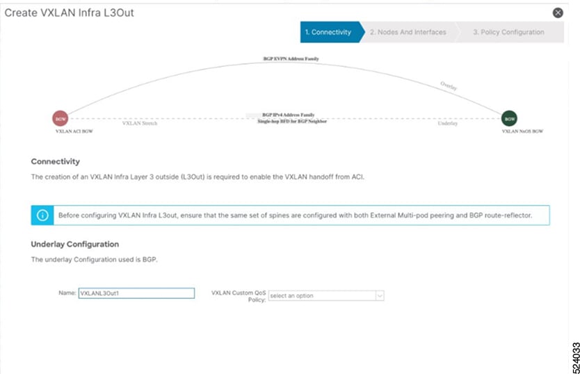
The Connectivity window appears.
Figure 10. VXLAN Infra L3Out Connectivity Window
Step 3
In the Connectivity window, enter the necessary information.
In the Name field, enter a name for the VXLAN Infra L3Out.
This will be the name for the policy controlling connectivity to the outside. The name can be up to 64 alphanumeric characters.
Note
You cannot change this name after the object has been saved.
(Optional) In the VXLAN Custom QoS Policy field, choose an existing QoS policy or choose Create VXLAN Custom QoS Policy to create a new QoS policy.
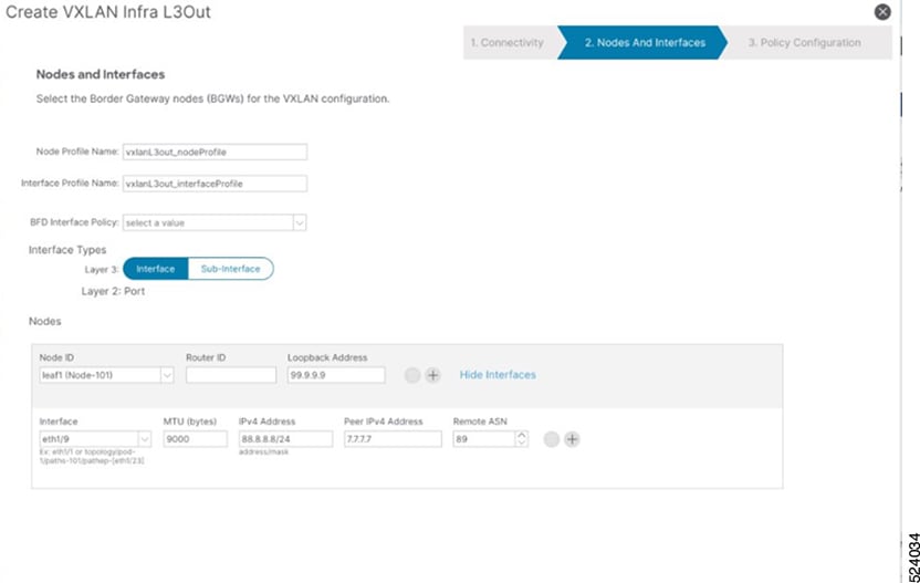
Figure 11. VXLAN Infra L3Out Nodes and Interfaces Window
Step 4
In the Nodes and Interfaces window, enter the necessary information to configure the border gateway nodes and interfaces.
In the Node Profile Name and Interface Profile Name fields, determine if you want to use the default naming convention for the node profile and interface profile names.
The default node profile name is L3Out-name_nodeProfile, and the default interface profile name is L3Out-name_interfaceProfile, where L3Out-name is the name that you entered in the Name field in the Connectivity page. Change the profile names in these fields, if necessary.
(Optional) In the BFD Interface Policy field, choose an existing BFD interface policy or choose Create BFD Interface Policy to create a new BFD interface policy.
In the Interface Types area, make the necessary selections in the Layer 3 and Layer 2 fields.
The options are:
Layer 3:
Interface: Choose this option to configure a Layer 3 interface to connect the border leaf switch to the external router.
Sub-Interface: Choose this option to configure a Layer 3 sub-interface to connect the border leaf switch to the external router.
From the Node ID field drop-down menu, choose the border gateway node for the VXLAN infra L3Out.
You might see the following warning message appear on your screen, describing how to configure the router ID.
The leaf switch 103 has a Operational Router ID 3.3.3.3 which is used for MP-BGP sessions running between this leaf and spines.
User can still configure a different Route ID than 3.3.3.3 but will flap the MP-BGP sessions which are already running on
this leaf.
If you do not have a router ID already configured for this node, go to 4.e for instructions on configuring a router ID for this node.
If you have a router ID already configured for this node (for example, if you had configured MP-BGP route reflectors previously).
Use the same router ID for the VXLAN configuration: The same router ID when using multiple infra L3Outs. This is the recommended option. Make a note of the router ID displayed
in this warning to use in the next step, 4.e.
In the Router ID field, enter a unique router ID (the IPv4 address) for the border gateway switch part of the infra L3Out.
The router ID must be unique across all border gateway switches and the non-ACI fabric border gateways.
As described in 4.d, if a router ID has already been configured on this node, you have several options:
If you want to use the same router ID for the VXLAN configuration, enter the router ID that was displayed in the warning message
in 4.d.
You must configure the same router ID when using multiple infra L3Outs.
Enter an IP address in the Loopback field. This is the routable control plane address which is used for EVPN peering, It is advertised via the underlay protocol.
In the the Interface field, choose a port from the drop-down list.
If you selected Sub-Interface in the Layer 3 area above, the VLAN Encap field appears. Enter the encapsulation used for the layer 3 outside profile.
In the MTU (bytes) field, enter the maximum transmit unit of the external network.
In the IPv4 Address field, enter an IP address for the eBGP underlay configuration.
This is the IP address assigned to the ACI border gateway Layer 3 interface/sub-interface that you configured in the previous
step.
In the Peer IPv4 Address field, enter the eBGP underlay unicast peer IP address.
This is the interface's IP address of the router directly connected to the border gateway switch.
In the Remote ASN field, enter the BGP Autonomous System Number of the directly-connected router.
Determine if you want to configure additional interfaces for this node for the VXLAN infra L3Out.
If you do not want to configure additional interfaces for this node for this VXLAN infra L3Out, skip to 4.o.
If you want to configure additional interfaces for this node for this VXLAN infra L3Out, click + in the Interfaces area to bring up the same options for another interface for this node.
Note
If you want to delete the information that you entered for an interface for this node, or if you want to delete an interface
row that you added by accident, click the trash can icon for the interface row that you want to delete.
Determine if you want to configure additional border gateways for this VXLAN infra L3Out.
If you do not want to configure additional border gateways for this VXLAN infra L3Out, skip to 4.o.
If you want to configure additional border gateways for this VXLAN infra L3Out, click + in the Nodes area to bring up the same options for another node.
Note
If you want to delete the information that you entered for a node, or if you want to delete a node row that you added by accident,
click the trash can icon for the node row that you want to delete.
Click Next.
The Policy Configuration window appears.
Figure 12. VXLAN Infra L3Out Policy Configuration Window
Step 5
In the Policy Configuration window, enter the necessary information to configure the border gateway nodes and interfaces.
In the Border Gateway Set field, determine if you want to use an existing border gateway set or create a new border gateway set.
Check the Configure VXLAN Remote Fabrics and configure the following fields:
In the Remote VXLAN Fabric field, specify an existing remote VXLAN fabric or click + to create a new remote VXLAN fabric.
In the Remote EVPN Peer Address field, specify the remote EVPN address.
This is the EVPN address that is used to identify the remote device with which the local device is communicating. The remote
EVPN address is used to establish the initial connection between the two devices, and it is also used to route the encrypted
traffic between them.
In the Remote AS field, enter the BGP autonomous system number of the remote NX-OS border gateway node to configure the remote AS for each
remote fabric peer.
In the TTL field, enter the connection time to live (TTL). The value must be greater than 1.
Step 6
Click Finish to complete the necessary configurations in the Create VXLAN Infra L3Out wizard.
Starting from Cisco APIC 6.1(2), you must configure a site ID. You will not be able to configure the border gateway set policy
if you do not have this site ID.
Note
If you have already configured the ACI Border Gateway feature for Cisco APIC 6.1(1), and upgrade to Cisco APIC 6.1(2) without
creating a VXLAN site ID a fault is generated for all the stretched VRFs and bridge domains.
Procedure
Step 1
From the top menu bar, navigate to Tenants > infra >Policies >VXLAN Gateway >VXLAN Site.
Step 2
Right-click on VXLAN Site and select Create VXLAN Site .
The Create VXLAN Site window appears.
Step 3
In the Name field, enter a name for your VXLAN site.
Step 4
In the ID field, enter a unique site ID for the VXLAN Site.
Step 5
(Optional) In the Description field, enter a description for the VXLAN Site.
Step 6
Click Submit.
Creating Border Gateway Sets Using the GUI
To create border gateway sets, complete the following procedure:
Before you begin
This policy assigns a data plane TEP for border gateways in each Pod, which is used to communicate with remote non-ACI fabrics.
This is the external anycast TEP for the Pod. Cisco APIC also allocates one internal anycast TEP for all the border gateways
within the fabric.
Procedure
Step 1
From the top menu bar, navigate to Tenants > infra >Policies >VXLAN Gateway >Border Gateway Sets.
Step 2
On the Border Gateway Set work pane, click Actions > Create Border Gateway Set Policy.
Step 3
The VXLAN Site ID field displays the unique site ID that you previously created in the Create VXLAN Site window. If you have not created a VXLAN site ID you, you will be prompted to so.
Step 4
In the Name field, assign a name to the Border Gateway Set Policy.
Step 5
In the External Data Plane IP field, enter a unique routable IP address for each Pod. Click + to enter the POD ID and the Address.
To create remote VXLAN fabrics, complete the following procedure:
Before you begin
This policy represents a unique remote non-ACI fabric and the configuration specific to this fabric. The remote fabric policy
provides the control plane peering connectivity on the associated border gateway set for a remote fabric.
Procedure
Step 1
From the top menu bar, navigate to Tenants > infra >Policies >VXLAN Gateway > Remote VXLAN Fabrics.
Step 2
On the Remote VXLAN Fabrics work pane, click Actions > Create Remote VXLAN Fabric.
Step 3
In the Name field, assign a name to the remote VXLAN fabric.
Step 4
To enter the Peer IP Address and its associated TTL, Click + in the Remote EVPN Peers section, and complete the following steps in the Create Remote EVPN Peer dialog box:
Note
For a infra peer TTL, you must specify a value greater than 1.
Peer Address: Enter the peer IP address. This is the loopback IP address of the remote NX-OS BGW device, which is used to establish the
EVPN control-plane adjacency.
(Optional) In the Description field, enter descriptive information about the remote EVPN policy.
Remote ASN: Enter a number that uniquely identifies the neighbor autonomous system. The Autonomous System Number can be in 4-byte as
plain format from 1 to 4294967295.
In the Peer Type field, the VXLAN BGW Connectivity is already selected.
Step 5
Click Ok.
Step 6
To enter the Associated Border Gateway Set, select an existing border gateway set from the drop down list or click + in the Associated Border Gateway Set box and select an existing border gateway set.
Using the procedure in this section, you can stretch tenant VRF(s) between the ACI and VXLAN EVPN domains. This ensures that
routed communications for the tenants between those domains can happen by leveraging the VXLAN data-plane encapsulation. Some
specific deployment considerations when stretching a tenant VRF are:
User tenant VRFs that are stretched are associated to a BGW set, which are associated to the VXLAN infra L3Out.
Only one VXLAN VRF L3Out is supported on each VRF. This is used to stretch the VRF towards a BGW.
Navigate to the Tenants > Networking > VXLAN Stretch.
Step 2
Right-click on VXLAN Stretch and select Create VXLAN VRF Stretch.
The Create VXLAN VRF Stretch window appears.
Step 3
In the VRF field, select an existing VRF or click Create VRF to create a new VRF with the following steps:
In the Name field, enter a name for the VRF.
In the Alias field, enter an alias name for the VRF.
(Optional) In the Descriptionfield, enter a description of the VRF.
In the Policy Control Enforcement Preference field, choose Unenforced. This will allow all EPGs to communicate freely without any restriction.
Each VRF has a policy enforcement option to define whether a security policy is enforced on the VRF. By default, the VRF is
in enforced mode, which means that a contract is required for inter-EPG communication. If a VRF is set to unenforced mode,
all EPGs in the VRF can communicate freely.
In the Policy Control Enforcement Direction field, choose Ingress.
In the OSPF Timers field, from the drop down list, choose the OSPF timer policy that you want to associate with this specific VRF (default or
Create OSPF Timers Policy).
In the Monitoring Policy field, from the drop down list, choose the Monitoring policy that you want to associate with this specific VRF.
Click Submit.
Step 4
In the Border Gateway Set field, select an existing border gateway set or click Create Border Gateway Set to create a new border gateway set.
Step 5
Starting from Cisco APIC 6.1(2), you do not have to specify the Remote Fabric Name or the Remote VNI as these options have been preselected.
Starting from Cisco APIC 6.1(4), you have to specify the Normalized VNI or the VNI used in the remote EVPN fabric for the VRF.
Note
The Local VNI is allocated by Cisco APIC. The ACI border gateways will perform the two-way translation between Cisco APIC assigned Local
VNI and the configured Normalized VNI.
Step 6
In the Outbound field, specify an outbound route map to control the routes that are advertised to the NX-OS site.
Configuring a VXLAN Bridge Domain Stretch Using the GUI
Using the procedure in this section, you can stretch tenant bridge domain (s) between the ACI and VXLAN EVPN domains. This
ensures that bridged communications for the tenants between those domains can happen by leveraging VXLAN data-plane encapsulation
Right-click on VXLAN Stretch and select Create VXLAN BD Stretch.
The Create VXLAN BD Stretch window appears.
Step 3
In the Bridge Domain field, select an existing bridge domain or click Create Bridge Domain to create a new bridge domain.
Step 4
In the Border Gateway Set field, select an existing border gateway set. As mentioned on the text box in the GUI, ensure that L2 Unknown Unicast is
set to flood for the bridge domain that is stretched.
Step 5
For Cisco APIC 6.1(2), you do not have to specify the Remote Fabric Name or the Remote VNI as these options have been preselected.
Starting from Cisco APIC 6.1(4), you have to specify the Normalized VNI or the VNI used in the remote EVPN fabric for the VRF.
Note
The Local VNI is allocated by Cisco APIC. The ACI border gateways will perform the two-way translation between Cisco APIC assigned Local
VNI and the configured Normalized VNI.
4
Step 6
Click Submit.
VXLAN Stretched Bridge Domain Selector
Use this procedure to create a VXLAN stretched bridge domain selector. You need to create this VXLAN stretched bridge domain
selector with policy-unaware VXLAN EVPN domains to classify all the Type-2 prefixes (endpoints) received from the remote NX-OS
border gateways as part of the specific ESG.
Procedure
Step 1
On the menu bar, choose Tenants and select the applicable Tenant.
Step 2
In the Navigation pane, expand tenant_name > Application Profiles > application_profile_name > Endpoint Security Groups > esg_name > Selectors.
Step 3
Right click VXLAN BD Selector and select Create a VXLAN BD Selector.
Step 4
In the Create a VXLAN BD Selector dialog box, enter the following information:
Bridge Domain: From the drop down, select the stretched bridge domain to be mapped.
Description: (Optional) A description of the selector.
Click Submit.
External Subnet Selectors
Use this procedure to create an External Subnet selector. You need to create an External Subnet selector with policy-unaware
VXLAN EVPN domains to classify as part of the specific ESG Type-5 prefixes (internal subnets or external resources) that are
received from the remote NX-OS border gateways.
Procedure
Step 1
On the menu bar, choose Tenants and select the applicable Tenant.
Step 2
In the Navigation pane, expand tenant_name > Application Profiles > application_profile_name > Endpoint Security Groups > esg_name > Selectors.
Step 3
Right click External Subnet Selectors and select Create a External Subnet Selector.
Step 4
In the Create a External Subnet Selector dialog box, enter the following information:
IP: Specify the IP prefix to be matched.
Description: (Optional) A description of the selector.
Shared: Put a check in the check box to share external subnets across the VRF, to enable shared security, configure external EPGs
with the shared security flags and subnets that you want to share.
Click Submit.
Note
The exact matches are needed for remote prefixes relative to bridge domain subnets.
The prefixes specified as VXLAN external subnet selectors do not need to exactly match the EVPN prefixes received from the
VXLAN EVPN fabrics. Super-net prefixes can be used to match remote prefixes relative to resources external to the fabric and
a catch-all behavior can also be achieved by specifying the 0.0.0.0/1 and 128.0.0.1 prefixes (since it is not possible to use 0.0.0.0/0).
Configuring a Remote Security Group Tag Under a Endpoint Security Group
Use this procedure to create a remote security group tag under a Endpoint Security Group.
Procedure
Step 1
On the menu bar, choose Tenants and select the applicable Tenant.
Step 2
In the Navigation pane, choose tenant_name > Application Profiles > application_profile_name > Endpoint Security Groups
Step 3
Right click Endpoint Security Groups and select Create Endpoint Security Group.
Step 4
In the STEP 1 > Identity page of the Create Endpoint Security Group dialog box, enter the following information:
Name: Enter a name for the ESG.
(Optional) Description: Enter the description of the ESG.
VRF: Enter the VRF that will be associated with the ESG.
Set Remote pcTag: Place a check in Set Remote pcTag check-box to set the remote pcTag.
Remote pcTag: Specify the Remote pcTag value that will be used for the Secured Group Translation (SGT) between the Cisco ACI fabric and
NX-OS site.
ESG Admin State: To shutdown the ESG, choose Admin Shut. By default, the ESG Admin State has the Admin Up value. This field was added beginning with the 5.2(3) release.
Deployment Immediacy: to specify the deployment immediacy for an ESG, choose On Demand or Immediate.
ESGs are always deployed with the deployment immediacy of On-demand, and the associated contract rules are programmed only after an endpoint that matches the ESG selectors are learned on the
given leaf node. Starting with Cisco ACI release 6.1(4), you can also select the Immediate option to deploy the ESGs.
If you have either the External Subnet selectors, External EPG selector or the Tag selector, which matches the external prefix/subnet,
configured under the ESG, then the Immediate option is automatically enforced.
Click Next.
The STEP 2 > Selectors page of the Create Endpoint Security Group dialog box opens.
Creating VXLAN Custom QoS Policy Using the GUI
VXLAN custom QoS policy defines the priority of the packets coming from a VXLAN EVPN fabric when they are forwarded inside
the ACI fabric based on the incoming inner DSCP values defined in the VXLAN QoS ingress policy. The CoS/DSCP values are set
in the inner header. It also marks the CoS and DSCP values in the outer header of the VXLAN encapsulated packets leaving the
ACI fabric toward a remote VXLAN EVPN fabric based on IPv4 DSCP values that are defined in VXLAN QoS egress policy. If no
custom egress policy is defined, the outer DSCP and CoS values are set to the default value of zero before leaving the ACI
fabric.
Procedure
Step 1
From the top menu bar, navigate to Tenants > infra > Networking > VXLAN L3Outs.
Step 2
Right-click on VXLAN L3Outs and choose Create VXLAN L3Out.
Step 3
In the Connectivity window, enter the necessary information.
Step 4
In the VXLAN Custom QoS Policy field, choose an existing QoS policy or choose Create VXLAN Custom QoS Policy to create a new QoS policy.
Step 5
In the Create VXLAN Custom QoS Policy window that opens, provide the name and description of the policy you're creating.
Step 6
In the VXLAN Ingress Rule area, click + to add an ingress QoS translation rule.
Data traffic coming into the border gateway connected to the ACI fabric will be checked for the inner DSCP value and if a
match is found, the traffic is classified into an ACI QoS Level and marked with appropriate COS and DSCP values, which are
set in the inner headers.
In the Priority field, select the priority for the ingress rule.
This is the QoS level you want to assign for the traffic within ACI fabric, which ACI uses to prioritize the traffic within
the fabric. This determines the COS values that are set in the external header of the iVXLAN encapsulated traffic, so that
it can be prioritized inside the ACI fabric.
The options range from Level 1 to Level 6. The default value is Level 3. If you do not make a selection in this field, the
traffic will automatically be assigned a Level 3 priority.
Using the DSCP Range From and DSCP Range To dropdowns, specify the range of inner DSCP values of the VXLAN traffic incoming from the remote VXLAN EVPN domain that you
want to match.
Use the Target DSCP to select the outer DSCP value to assign to the packet when it's inside the ACI fabric.
In the Target COS field, select the COS value to assign to the packet in the header when it's inside the ACI fabric.
The COS value specified is set in the original traffic received from the VXLAN EVPN domain, so it will be re-exposed only
when the traffic is VXLAN decapsulated on the destination ACI leaf node.
The default is Unspecified, which means that the original COS value of the packet will be retained, but only if the COS preservation
option is enabled in the fabric.
Click Update to save the ingress rule.
Repeat this step for any additional ingress QOS policy rules.
Step 7
In the VXLAN Egress Rule area, click + to add an egress QOS translation rule.
Using the DSCP Range From and DSCP Range To dropdowns, specify the range of inner DSCP values of the iVXLAN traffic originated by ACI leaf nodes and received by the
ACI border gateways that you want to match for and then assign the outer COS and DSCP values to VXLAN traffic destined to
the remote VXLAN EVPN domain.
From the Target Overlay DSCP dropdown, select the outer DSCP value that you want to assign to the egressing VXLAN packet.
From the Target COS dropdown, select the outer COS value that you want to assign to the egressing VXLAN packet.
Click Update to save the ingress rule.
Repeat this step for any additional egress QoS policy rules.
Step 8
Click OK to complete the creation of the custom VXLAN QoS Policy.


 Feedback