Remote Leaf Switches

This chapter contains the following sections:

About Remote Leaf Switches in the ACI Fabric

With an ACI fabric deployed, you can extend ACI services and APIC management to remote data centers with Cisco ACI leaf switches that have no local spine switch or APIC attached.

The remote leaf switches are added to an existing pod in the fabric. All policies deployed in the main data center are deployed in the remote switches, which behave like local leaf switches belonging to the pod. In this topology, all unicast traffic is through VXLAN over Layer 3. Layer 2 broadcast, unknown unicast, and multicast (BUM) messages are sent using Head End Replication (HER) tunnels without the use of Layer 3 multicast (bidirectional PIM) over the WAN. Any traffic that requires use of the spine switch proxy is forwarded to the main data center.

The APIC system discovers the remote leaf switches when they come up. From that time, they can be managed through APIC, as part of the fabric.


Note


  • All inter-VRF traffic (pre-release 4.0(1)) goes to the spine switch before being forwarded.

  • For releases prior to Release 4.1(2), before decommissioning a remote leaf switch, you must first delete the vPC.


Characteristics of Remote Leaf Switch Behavior in Release 4.0(1)

Starting in Release 4.0(1), remote leaf switch behavior takes on the following characteristics:

  • Reduction of WAN bandwidth use by decoupling services from spine-proxy:

    • PBR: For local PBR devices or PBR devices behind a vPC, local switching is used without going to the spine proxy. For PBR devices on orphan ports on a peer remote leaf, a RL-vPC tunnel is used. This is true when the spine link to the main DC is functional or not functional.

    • ERSPAN: For peer destination EPGs, a RL-vPC tunnel is used. EPGs on local orphan or vPC ports use local switching to the destination EPG. This is true when the spine link to the main DC is functional or not functional.

    • Shared Services: Packets do not use spine-proxy path reducing WAN bandwidth consumption.

    • Inter-VRF traffic is forwarded through an upstream router and not placed on the spine.

    • This enhancement is only applicable for a remote leaf vPC pair. For communication across remote leaf pairs, a spine proxy is still used.

  • Resolution of unknown L3 endpoints (through ToR glean process) in a remote leaf location when spine-proxy is not reachable.

Characteristics of Remote Leaf Switch Behavior in Release 4.1(2)

Before Release 4.1(2), all local switching (within the remote leaf vPC peer) traffic on the remote leaf location is switched directly between endpoints, whether physical or virtual, as shown in the following figure.

Figure 1. Local Switching Traffic: Prior to Release 4.1(2)

In addition, before Release 4.1(2), traffic between the remote leaf switch vPC pairs, either within a remote location or between remote locations, is forwarded to the spine switches in the ACI main data center pod, as shown in the following figure.

Figure 2. Remote Switching Traffic: Prior to Release 4.1(2)

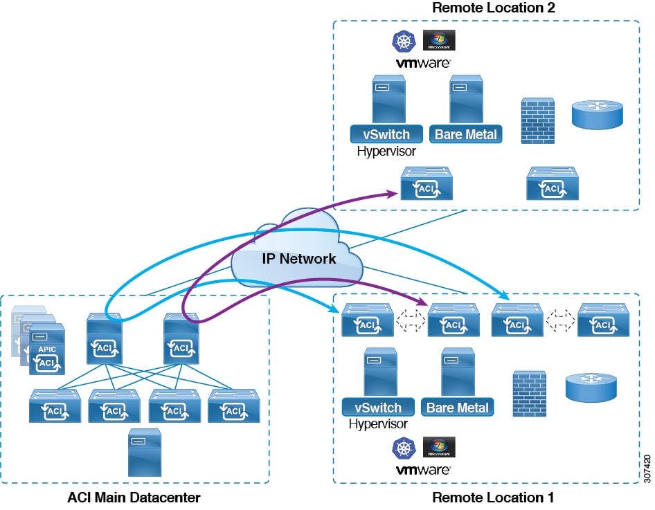
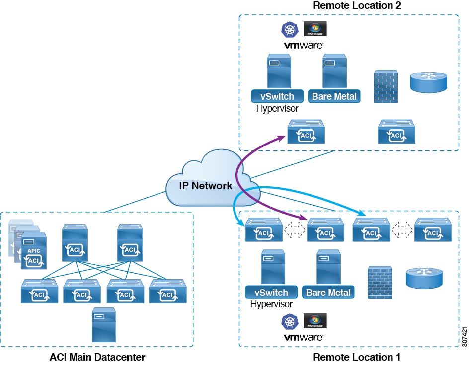
Starting in Release 4.1(2), support is now available for direct traffic forwarding between remote leaf switches in different remote locations. This functionality offers a level of redundancy and availability in the connections between remote locations, as shown in the following figure.

Figure 3. Remote Leaf Switch Behavior: Release 4.1(2)

In addition, remote leaf switch behavior also takes on the following characteristics starting in release 4.1(2):

  • Starting with Release 4.1(2), with direct traffic forwarding, when a spine switch fails within a single-pod configuration, the following occurs:

    • Local switching will continue to function for existing and new end point traffic between the remote leaf switch vPC peers, as shown in the "Local Switching Traffic: Prior to Release 4.1(2)" figure above.

    • For traffic between remote leaf switches across remote locations:

      • New end point traffic will fail because the remote leaf switch-to-spine switch tunnel would be down. From the remote leaf switch, new end point details will not get synced to the spine switch, so the other remote leaf switch pairs in the same or different locations cannot download the new end point information from COOP.

      • For uni-directional traffic, existing remote end points will age out after 300 secs, so traffic will fail after that point. Bi-directional traffic within a remote leaf site (between remote leaf VPC pairs) in a pod will get refreshed and will continue to function. Note that bi-directional traffic to remote locations (remote leaf switches) will be affected as the remote end points will be expired by COOP after a timeout of 900 seconds.

      • For shared services (inter-VRF), bi-directional traffic between end points belonging to remote leaf switches attached to two different remote locations in the same pod will fail after the remote leaf switch COOP end point age-out time (900 sec). This is because the remote leaf switch-to-spine COOP session would be down in this situation. However, shared services traffic between end points belonging to remote leaf switches attached to two different pods will fail after 30 seconds, which is the COOP fast-aging time.

      • L3Out-to-L3Out communication would not be able to continue because the BGP session to the spine switches would be down.

  • When there is remote leaf direct uni-directional traffic, where the traffic is sourced from one remote leaf switch and destined to another remote leaf switch (which is not the vPC peer of the source), there will be a milli-second traffic loss every time the remote end point (XR EP) timeout of 300 seconds occurs.

  • With a remote leaf switches with ACI Multi-Site configuration, all traffic continues from the remote leaf switch to the other pods and remote locations, even with a spine switch failure, because traffic will flow through an alternate available pod in this situation.

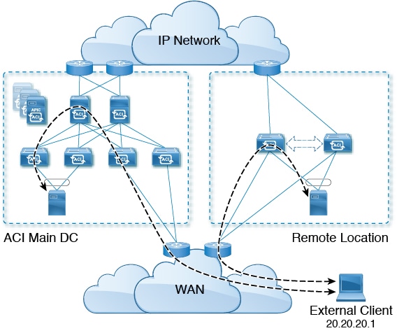
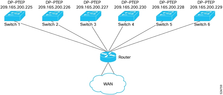
10 Mbps Bandwidth Support in IPN for Remote Leaf Switches

You might have situations where most of the data traffic from the remote leaf switches is local and the Inter-Pod Network (IPN) is needed only for management purposes. In these situations, you may not need a 100 Mbps IPN. To support these environments, starting with Release 4.2(4), support is now available for 10 Mbps as a minimum bandwidth in the IPN.

To support this, the following requirements should be met:

  • The IPN path is only used for managing remote leaf switches (management functions such as upgrades and downgrades, discovery, COOP, and policy pushes).

  • Configure IPN with the QoS configuration in order to prioritize control and management plane traffic between the Cisco ACI datacenter and remote leaf switch pairs based on the information provided in the section "Creating DSCP Translation Policy Using Cisco APIC GUI".

  • All traffic from the Cisco ACI datacenter and remote leaf switches is through the local L3Out.

  • The EPG or bridge domain are not stretched between the remote leaf switch and the ACI main datacenter.

  • You should pre-download software images on the remote leaf switches to reduce upgrade time.

The following figure shows a graphical representation of this feature.

Figure 4. Remote Leaf Switch Behavior, Release 4.2(4): Remote Leaf Switch Management through IPN

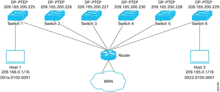
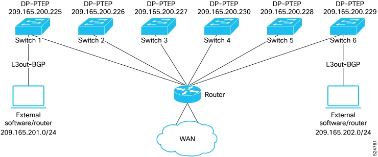
Dot1q Tunnel Support on Remote Leaf Switches

In some situations, a co-location provider might be hosting multiple customers, where each customer is using thousands of VLANs per remote leaf switch pair. Starting with Release 4.2(4), support is available to create an 802.1Q tunnel between the remote leaf switch and the ACI main datacenter, which provides the flexibility to map multiple VLANs into a single 802.1Q tunnel, thereby reducing the EPG scale requirement.

The following figure shows a graphical representation of this feature.

Figure 5. Remote Leaf Switch Behavior, Release 4.2(4): 802.1Q Tunnel Support on Remote Leaf Switches

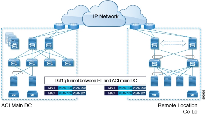
Create this 802.1Q tunnel between the remote leaf switch and the ACI main datacenter using the instructions provided in the "802.1Q Tunnels" chapter in the Cisco APIC Layer 2 Networking Configuration Guide, located in the Cisco APIC documentation landing page.

You can configure remote leaf switches in the APIC GUI, either with and without a wizard, or use the REST API or the NX-OS style CLI.

Remote Leaf Switch Hardware Requirements

The following switches are supported for the remote leaf switch feature.

Fabric Spine Switches

For the spine switch at the Cisco Application Centric Infrastructure (ACI) main data center that is connected to the WAN router, the following spine switches are supported:

  • Fixed spine switches Cisco Nexus 9000 series:

    • N9K-C9332C

    • N9K-C9364C

    • All GX and GX2 switches

  • For modular spine switches, only Cisco Nexus 9000 series switches with names that end in EX, and later (for example, N9K-X9732C-EX) are supported.

  • Older generation spine switches, such as the fixed spine switch N9K-C9336PQ or modular spine switches with the N9K-X9736PQ linecard are supported in the main data center, but only next generation spine switches are supported to connect to the WAN.

Remote Leaf Switches

  • For the remote leaf switches, only Cisco Nexus 9000 series switches with names that end in EX, and later (for example, N9K-C93180LC-EX) are supported.

  • The remote leaf switches must be running a switch image of 13.1.x or later (aci-n9000-dk9.13.1.x.x.bin) before they can be discovered. This may require manual upgrades on the leaf switches.

Remote Leaf Switch Restrictions and Limitations

The following guidelines and restrictions apply to remote leaf switches:

  • The remote leaf solution requires the /32 tunnel end point (TEP) IP addresses of the remote leaf switches and main data center leaf/spine switches to be advertised across the main data center and remote leaf switches without summarization.

  • If you move a remote leaf switch to a different site within the same pod and the new site has the same node ID as the original site, you must delete and recreate the virtual port channel (vPC).

  • With the Cisco N9K-C9348GC-FXP switch, you can perform the initial remote leaf switch discovery only on ports 1/53 or 1/54. Afterward, you can use the other ports for fabric uplinks to the ISN/IPN for the remote leaf switch.

  • Beginning with the 6.0(3) release, when you have dynamic packet prioritization enabled and either a CoS preservation policy or a Cisco ACI Multi-Pod policy enabled, the expected behavior is mice flows should egress the fabric with a VLAN CoS priority of 0 if you also enabled CoS preservation or if you also enabled Cisco ACI Multi-Pod DSCP translation along with dynamic packet prioritization. However, the actual behavior is as follows:

    • Mice flows egress the fabric with the VLAN CoS priority of 0 if you enabled CoS preservation with the dynamic packet prioritization feature in the physical leaf and remote leaf switches.

    • Mice flows egress the fabric with the VLAN CoS priority of 0 if you enabled Cisco ACI Multi-Pod DSCP translation with the dynamic packet prioritization feature in a physical leaf switch.

    • Mice flows egress the fabric with the VLAN CoS priority of 3 if you enabled Cisco ACI Multi-Pod DSCP translation with the dynamic packet prioritization feature in a remote leaf switch.

    If you do not want the mice flows to have a VLAN CoS priority of 3 when they egress a remote leaf switch on which you enbled Cisco ACI Multi-Pod DSCP translation, use the CoS preservation feature instead.

The following sections provide information on what is supported and not supported with remote leaf switches:

Supported Features

Beginning with Cisco APIC release 6.1(1), fabric ports (uplinks) can now be configured with user tenant L3Outs and SR-MPLS Infra L3Outs, as a routed sub-interface.

  • Only L3Outs with routed sub-interface are allowed on fabric ports of remote leaf.

  • Remote leaf fabric ports can only be deployed as an L3Out of a user tenant or SR-MPLS Infra L3Out.

  • You cannot deploy remote leaf fabric ports on an application EPG. Only L3Outs with routed sub-interface are allowed.

  • Only the PTP/Sync access policies are supported on a hybrid port. No other access policies are supported.

  • Only fabric SPAN is supported on the hybrid port.

  • Netflow is not supported on fabric port that is configured with a user tenant L3Out.

Beginning with Cisco APIC release 6.0(4), stretching of an L3Out SVI across vPC remote leaf switch pairs is supported.

Beginning with Cisco APIC release 4.2(4), the 802.1Q (Dot1q) tunnels feature is supported.

Beginning with Cisco APIC release 4.1(2), the following features are supported:

  • Remote leaf switches with ACI Multi-Site

  • Traffic forwarding directly across two remote leaf vPC pairs in the same remote data center or across data centers, when those remote leaf pairs are associated to the same pod or to pods that are part of the same multipod fabric

  • Transit L3Out across remote locations, which is when the main Cisco ACI data center pod is a transit between two remote locations (the L3Out in RL location-1 and L3Out in RL location-2 are advertising prefixes for each other)

Beginning with Cisco APIC release 4.0(1), the following features are supported:

  • Q-in-Q Encapsulation Mapping for EPGs

  • PBR Tracking on remote leaf switches (with system-level global GIPo enabled)

  • PBR Resilient Hashing

  • Netflow

  • MacSec Encryption

  • Troubleshooting Wizard

  • Atomic counters

Unsupported Features

Full fabric and tenant policies are supported on remote leaf switches in this release with the exception of the following features, which are unsupported:

  • GOLF

  • vPod

  • Floating L3Out

  • Stretching of L3Out SVI between local leaf switches (ACI main data center switches) and remote leaf switches or stretching across two different vPC pairs of remote leaf switches

  • Copy service is not supported when deployed on local leaf switches and when the source or destination is on the remote leaf switch. In this situation, the routable TEP IP address is not allocated for the local leaf switch. For more information, see the section "Copy Services Limitations" in the "Configuring Copy Services" chapter in the Cisco APIC Layer 4 to Layer 7 Services Deployment Guide, available in the APIC documentation page.

  • Layer 2 Outside Connections (except Static EPGs)

  • Copy services with vzAny contract

  • FCoE connections on remote leaf switches

  • Flood in encapsulation for bridge domains or EPGs

  • Fast Link Failover policies are for ACI fabric links between leaf and spine switches, and are not applicable to remote leaf connections. Alternative methods are introduced in Cisco APIC Release 5.2(1) to achieve faster convergence for remote leaf connections.

  • Managed Service Graph-attached devices at remote locations

  • Traffic Storm Control

  • Cloud Sec Encryption

  • First Hop Security

  • Layer 3 Multicast routing on remote leaf switches

  • Maintenance mode

  • TEP to TEP atomic counters

The following scenarios are not supported when integrating remote leaf switches in a Multi-Site architecture in conjunction with the intersite L3Out functionality:

  • Transit routing between L3Outs deployed on remote leaf switch pairs associated to separate sites

  • Endpoints connected to a remote leaf switch pair associated to a site communicating with the L3Out deployed on the remote leaf switch pair associated to a remote site

  • Endpoints connected to the local site communicating with the L3Out deployed on the remote leaf switch pair associated to a remote site

  • Endpoints connected to a remote leaf switch pair associated to a site communicating with the L3Out deployed on a remote site


Note


The limitations above do not apply if the different data center sites are deployed as pods as part of the same Multi-Pod fabric.


The following deployments and configurations are not supported with the remote leaf switch feature:

  • It is not supported to stretch a bridge domain between remote leaf nodes associated to a given site (APIC domain) and leaf nodes part of a separate site of a Multi-Site deployment (in both scenarios where those leaf nodes are local or remote) and a fault is generated on APIC to highlight this restriction. This applies independently from the fact that BUM flooding is enabled or disabled when configuring the stretched bridge domain on the Multi-Site Orchestrator (MSO). However, a bridge domain can always be stretched (with BUM flooding enabled or disabled) between remote leaf nodes and local leaf nodes belonging to the same site (APIC domain).

  • Spanning Tree Protocol across remote leaf switch location and main data center.

  • APICs directly connected to remote leaf switches.

  • Orphan port channel or physical ports on remote leaf switches, with a vPC domain (this restriction applies for releases 3.1 and earlier).

  • With and without service node integration, local traffic forwarding within a remote location is only supported if the consumer, provider, and services nodes are all connected to remote leaf switches are in vPC mode.

  • /32 loopbacks advertised from the spine switch to the IPN must not be suppressed/aggregated toward the remote leaf switch. The /32 loopbacks must be advertised to the remote leaf switch.

Changes For Release 5.0(1)

Beginning with Cisco APIC release 5.0(1), the following changes have been applied for remote leaf switches:

  • The direct traffic forwarding feature is enabled by default and cannot be disabled.

  • A configuration without direct traffic forwarding for remote leaf switches is no longer supported. If you have remote leaf switches and you are upgrading to Cisco APIC Release 5.0(1), review the information provided in the section "About Direct Traffic Forwarding" and enable direct traffic forwarding using the instructions in that section.

Changes For Release 5.2(3)

Beginning with Cisco APIC release 5.2(3), the following changes have been applied for remote leaf switches:

  • The IPN underlay protocol to peer between the remote leaf switches and the upstream router can be either OSPF or BGP. In previous releases, only an OSPF underlay is supported.

WAN Router and Remote Leaf Switch Configuration Guidelines

Before a remote leaf is discovered and incorporated in APIC management, you must configure the WAN router and the remote leaf switches.

Configure the WAN routers that connect to the fabric spine switch external interfaces and the remote leaf switch ports, with the following requirements:

WAN Routers

  • Enable OSPF on the interfaces, with the same details, such as area ID, type, and cost.

  • Configure DHCP Relay on the interface leading to each APIC's IP address in the main fabric.

  • The interfaces on the WAN routers which connect to the VLAN-5 interfaces on the spine switches must be on different VRFs than the interfaces connecting to a regular multipod network.

Remote Leaf Switches

  • Connect the remote leaf switches to an upstream router by a direct connection from one of the fabric ports. The following connections to the upstream router are supported:

    • 40 Gbps & higher connections

    • With a QSFP-to-SFP Adapter, supported 1G/10G SFPs

    Bandwidth in the WAN varies, depending on the release:

    • For releases prior to 4.2(4), bandwidth in the WAN must be a minimum of 100 Mbps and maximum supported latency is 300 msecs.

    • For Release 4.2(4) and later, bandwidth in the WAN must be a minimum of 10 Mbps and maximum supported latency is 300 msecs.

  • It is recommended, but not required to connect the pair of remote leaf switches with a vPC. The switches on both ends of the vPC must be remote leaf switches at the same remote datacenter.

  • Configure the northbound interfaces as Layer 3 sub-interfaces on VLAN-4, with unique IP addresses.

    If you connect more than one interface from the remote leaf switch to the router, configure each interface with a unique IP address.

  • Enable OSPF on the interfaces, but do not set the OSPF area type as stub area.

  • The IP addresses in the remote leaf switch TEP Pool subnet must not overlap with the pod TEP subnet pool. The subnet used must be /24 or lower.

  • Multipod is supported, but not required, with the Remote Leaf feature.

  • When connecting a pod in a single-pod fabric with remote leaf switches, configure an L3Out from a spine switch to the WAN router and an L3Out from a remote leaf switch to the WAN router, both using VLAN-4 on the switch interfaces.

  • When connecting a pod in a multipod fabric with remote leaf switches, configure an L3Out from a spine switch to the WAN router and an L3Out from a remote leaf switch to the WAN router, both using VLAN-4 on the switch interfaces. Also configure a multipod-internal L3Out using VLAN-5 to support traffic that crosses pods destined to a remote leaf switch. The regular multipod and multipod-internal connections can be configured on the same physical interfaces, as long as they use VLAN-4 and VLAN-5.

  • When configuring the Multipod-internal L3Out, use the same router ID as for the regular multipod L3Out, but deselect the Use Router ID as Loopback Address option for the router-id and configure a different loopback IP address. This enables ECMP to function.

  • Starting with the 6.0(1) release, remote leaf switches support remote pools with a subnet mask of up to /28. In prior releases, remote leaf switches supported remote pools with a subnet mask of up to /24. You can remove remote pools only after you have decommissioned and removed them from the fabric including all the nodes that are using that pool.

    The /28 remote TEP pool supports a maximum of four remote leaf switches with two vPC pairs. We recommend that you keep two IP addresses unused for RMA purposes. These two IP addresses are sufficient to do an RMA of one switch. The following table shows how the remote leaf switches use these IP addresses:


    Note


    Two IP addresses are used for internal fabric usage.


    IP Address Type

    Quantity

    Total usable IP addresses available in the /28 pool

    16 - 2 = 14

    Number of IP addresses used internally by the fabric

    2

    Total usable IP addresses available for nodes

    14 - 2 = 12

    Number of IP addresses required for 4 remote leaf switches

    4 * 2 = 8

    Number of IP addresses required for 2 vPC pairs

    2 * 1 =2

    Total used IP addresses in the remote pool

    8 + 2 = 10

    Free IP addresses in the /28 remote pool

    12 - 10 = 2

    When you decommission a remote leaf switch, two IP addresses are freed, but are available for reuse only after 24 hours have passed.

Configure the Pod and Fabric Membership for Remote Leaf Switches Using the GUI

You can configure and enable Cisco APIC to discover and connect the IPN router and remote switches, either by using a wizard or by using the APIC GUI, without a wizard.

About Direct Traffic Forwarding

As described in Characteristics of Remote Leaf Switch Behavior in Release 4.1(2), support for direct traffic forwarding is supported starting in Release 4.1(2), and is enabled by default starting in Release 5.0(1) and cannot be disabled. However, the method that you use to enable or disable direct traffic forwarding varies, depending on the version of software running on the remote leaf switches:

  • If your remote leaf switches are currently running on Release 4.1(2) or later [if the remote leaf switches were never running on a release prior to 4.1(2)], go to the "Configure the Pod and Fabric Membership for Remote Leaf Switches Using a Wizard" procedure.

  • If your remote leaf switches are currently running on a release prior to 4.1(2), go to the "Upgrade the Remote Leaf Switches and Enable Direct Traffic Forwarding" procedure to upgrade the switches to Release 4.1(2) or later, then make the necessary configuration changes and enable direct traffic forwarding on those remote leaf switches.

  • If your remote leaf switches are running on Release 4.1(2) or later and have direct traffic forwarding enabled, but you want to downgrade to a release prior to 4.1(2), go to the "Disable Direct Traffic Forwarding and Downgrade the Remote Leaf Switches" procedure to disable the direct traffic forwarding feature before downgrading those remote leaf switches.

  • If your remote leaf switches are running on a release prior to Release 5.0(1) and you want to upgrade to Release 5.0(1) or later:

    1. If your remote leaf switches are running on a release prior to 4.1(2), first upgrade to release 4.1(2) and enable direct traffic forwarding on those remote switches using the procedures described in the "Upgrade the Remote Leaf Switches and Enable Direct Traffic Forwarding" procedure.

    2. Once your remote leaf switches are on Release 4.1(2) and have direct traffic forwarding enabled, upgrade the remote leaf switches to Release 5.0(1) or later.

  • If your remote leaf switches are running on Release 5.0(1) or later, where direct traffic forwarding is enabled by default, and you want to downgrade to any of these previous releases that also supported direct traffic forwarding:

    • Release 4.2(x)

    • Release 4.1(2)

    Then direct traffic forwarding may or may not continue to be enabled by default, depending on your configuration:

    • If both Routable Subnets and Routable Ucast were enabled for all pods prior to the downgrade, then direct traffic forwarding continues to be enabled by default after the downgrade.

    • If Routable Subnets were enabled for all pods but Routable Ucast was not enabled, then direct traffic forwarding is not enabled after the downgrade.

Remote Leaf Switch Failover

Beginning in Cisco Application Policy Infrastructure Controller (APIC) Release 4.2(2), remote leaf switches are pod redundant. That is, in a multipod setup, if a remote leaf switch in a pod loses connectivity to the spine switch, it is moved to another pod. This enables traffic between endpoints of the remote leaf switches that are connected to the original pod to work.

Remote leaf switches are associated, or pinned, to a pod, and the spine proxy path is determined through the configuration. In previous releases, Council of Oracle Protocol (COOP) communicated mapping information to the spine proxy. Now, when communication to the spine switch fails, COOP sessions move to a pod on another spine switch.

Previously, you added a Border Gateway Protocol (BGP) route reflector to the pod. Now you use an external route reflector and make sure that the remote leaf switches in the pod have a BGP relationship with other pods.

Remote leaf switch failover is disabled by default. You enable Remote Leaf Pod Redundancy Policy in the Cisco Application Policy Infrastructure Controller (APIC) GUI under the Systems > System Settings tab. You also can enable redundancy pre-emption. If you enable pre-emption, the remote leaf switch is reassociated with the parent pod once that pod is back up. If you do not enable pre-emption, the remote leaf remains associated with the operational pod even when the parent pod comes back up.


Note


Movement of a remote leaf switch from one pod to another could result in traffic disruption of several seconds.

Remote leaf resiliency

Challenges with remote leaf architecture

The current remote leaf architecture ties the APIC, control plane, and data plane directly to the spine switches of the main Pod.

This architecture has these constraints:

  • Remote leaf endpoint (EP) learning relies on the control plane associated with the main Pod.

  • Remote leaf L3Out external prefixes rely on the BGP configuration associated with the main Pod.

  • Any failure in connectivity to main Pod spine can affect traffic forwarding in remote leaf nodes.

Remote leaf resiliency

Remote leaf resiliency is achieved using a group consisting of multiple remote leaves. When this group is created, remote leaves within the remote leaf resiliency group form a fully meshed BGP EVPN session to exchange endpoint and external prefix information. Any failure in the WAN or the main Pod does not affect traffic within the remote leaf resiliency group.

In a remote leaf resiliency deployment, remote leaves in the group communicate using BGP EVPN based standard approach instead of a Cisco proprietary protocol.

This solution

  • establishes local BGP EVPN mesh sessions within the remote leaf resiliency group to facilitate endpoint learning

  • establishes full mesh VPNv4 and VPNv6 sessions within the remote leaf resiliency group to distribute L3Out external prefixes

  • utilizes BGP EVPN-learned endpoints within the remote leaf resiliency group for data forwarding, and

  • utilizes COOP learned endpoints between remote leaf sites and the main Pod.


Note


Migration to or from remote leaf resiliency group must be performed during a maintenance window.


Limitations of remote leaf resiliency group

Remote leaf resiliency group has these limitations.

  • Remote leaf TEP pool cannot be configured under multiple remote leaf resiliency groups.

  • Remote leaf TEP pools from different Pods cannot be configured within the same remote leaf resiliency group.

Create remote leaf resiliency group using the GUI

Follow these steps to create a remote leaf resiliency group using the GUI.

Before you begin

All the spines and the ToR switch in the fabric ACI site must be upgraded to R6.1.3 before enabling remote leaf resiliency group feature in the fabric.

Procedure


Step 1

On the menu bar, choose Fabric > Inventory.

Step 2

In the Navigation pane, choose Pod Fabric Setup Policy.

The Pod Fabric Setup Policy pane appears.

Step 3

Double-click a Pod.

The Fabric Setup Policy for a POD pane appears.

Step 4

Navigate to the Autonomous RL Group area and click the + symbol.

The Create Autonomous RL Group dialog box appears.

Step 5

Enter the remote leaf resiliency group name in the Group Name field.

Step 6

Click the + symbol in the Remote IDs field and choose a TEP pool to group the remote leaves into this group.

Step 7

Click Submit to create a remote leaf resiliency group.

The remote leaf resiliency group details appear in the Autonomous RL Group area of Fabric Setup Policy pane.


Verify remote leaf resiliency configurations using the CLI

ARL Diagram

All six switches are configured into a single group.

Follow these steps to verify remote leaf resiliency configurations using the CLI.

Procedure


Step 1

Run the show bgp l2vpn evpn summary vrf all command to display the full mesh BGP L2VPN or EVPN sessions among all the remote leaves.

Example:

Switch1# show bgp l2vpn evpn summary vrf all
BGP summary information for VRF overlay-1, address family L2VPN EVPN
BGP router identifier 105.1.1.1, local AS number 100
BGP table version is 254997, L2VPN EVPN config peers 5, capable peers 5
117325 network entries and 130831 paths using 22327320 bytes of memory
BGP attribute entries [2374/493792], BGP AS path entries [0/0]
BGP community entries [0/0], BGP clusterlist entries [1/4]

Neighbor        V    AS MsgRcvd MsgSent   TblVer  InQ OutQ Up/Down  State/PfxRcd
209.165.200.230      4   100  130445     291   254997    0    0 01:43:11 13908
209.165.200.226      4   100  149893     291   254997    0    0 01:43:11 8402
209.165.200.228      4   100     218     169   254997    0    0 01:43:02 1
209.165.200.229      4   100   69471     208   254997    0    0 01:30:49 30399
209.165.200.227      4   100    3505     291   254997    0    0 01:43:10 201

Step 2

Run the show bgp vpn unicast summary vrf overlay command to display the full mesh BGP VPN4 and VPN6 sessions among all the remote leaves.

Example:

leaf5# show bgp vpnv4 unicast summary vrf overlay-1
BGP summary information for VRF overlay-1, address family VPNv4 Unicast
BGP router identifier 105.1.1.1, local AS number 100
BGP table version is 115527, VPNv4 Unicast config peers 7, capable peers 7
31202 network entries and 40403 paths using 5165136 bytes of memory
BGP attribute entries [1400/291200], BGP AS path entries [0/0]
BGP community entries [0/0], BGP clusterlist entries [1/4]

Neighbor           V    AS MsgRcvd MsgSent   TblVer  InQ OutQ Up/Down  State/PfxRcd
11.1.1.165         4   100   57163     249   115527    0    0 01:45:33 400  >>>  This is session with spine 1
11.1.1.240         4   100   57724     249   115527    0    0 01:45:34 400  >>> This is session with spine 2
209.165.200.230    4   100  130447     293   115527    0    0 01:45:37 2400
209.165.200.226    4   100  149895     293   115527    0    0 01:45:38 2400
209.165.200.228    4   100     220     171   115527    0    0 01:45:29 0
209.165.200.229    4   100   69723     210   115527    0    0 01:33:16 4400
209.165.200.227    4   100    3507     293   115527    0    0 01:45:37 0
leaf5# show bgp vpnv6 unicast summary vrf overlay-1
BGP summary information for VRF overlay-1, address family VPNv6 Unicast
BGP router identifier 105.1.1.1, local AS number 100
BGP table version is 101009, VPNv6 Unicast config peers 7, capable peers 7
26895 network entries and 31990 paths using 4779900 bytes of memory
BGP attribute entries [1200/249600], BGP AS path entries [0/0]
BGP community entries [0/0], BGP clusterlist entries [1/4]

Neighbor           V    AS MsgRcvd MsgSent   TblVer  InQ OutQ Up/Down  State/PfxRcd
11.1.1.165         4   100   57164     250   101009    0    0 01:46:04 200
11.1.1.240         4   100   57725     250   101009    0    0 01:46:04 200
209.165.200.230    4   100  130448     294   101009    0    0 01:46:08 2400
209.165.200.226    4   100  149896     294   101009    0    0 01:46:08 2400
209.165.200.228    4   100     221     172   101009    0    0 01:45:59 0
209.165.200.229    4   100   69733     211   101009    0    0 01:33:46 2810
209.165.200.227    4   100    3508     294   101009    0    0 01:46:08 0

Verify endpoint to endpoint communication using the CLI

For Switch1, 209.166.0.1 (EPG-1) is local learnt EP and 209.165.0.1 (EPG-2) is remote EP. For switch6, 209.165.0.1 is locally learnt EP and 209.166.0.1 is remote EP. Both the endpoints are in the different subnets and both the EPGs are stretched at both switch1 and switch6. The CLI output taken on Switch1 for local and remote EPs are shown for each component.

ARL Diagram

Follow these steps to verify the EP to EP communication using the CLI.

Procedure


Step 1

Run the show system internal epm endpoint ip command to check the local EP and remote EP entries in Switch1 in EPM.

Example:


Switch1# show system internal epm endpoint ip 209.166.0.1
MAC : 001e.0100.0001 ::: Num IPs : 1
IP# 0 : 209.166.0.1 ::: IP# 0 flags :  ::: l3-sw-hit: No
Vlan id : 124 ::: Vlan vnid : 19003 ::: VRF name : ARL_Scale:ctx-1
BD vnid : 16023537 ::: VRF vnid : 2490424
Phy If : 0x1a014000 ::: Tunnel If : 0
Interface : Ethernet1/21
Flags : 0x80004c04 ::: sclass : 16388 ::: Ref count : 5
EP Create Timestamp : 02/05/2025 08:01:55.278575
EP Update Timestamp : 02/05/2025 09:21:27.898869
EP Flags : local|IP|MAC|sclass|timer|

Switch1# show system internal epm endpoint ip 209.165.0.1
MAC : 0000.0000.0000 ::: Num IPs : 1
IP# 0 : 209.165.0.1 ::: IP# 0 flags :  ::: l3-sw-hit: No
Vlan id : 0 ::: Vlan vnid : 0 ::: VRF name : ARL_Scale:ctx-1
BD vnid : 0 ::: VRF vnid : 2490424
Phy If : 0 ::: Tunnel If : 0x1801000b
Interface : Tunnel11
Flags : 0x80004410 ::: sclass : 16388 ::: Ref count : 3
EP Create Timestamp : 02/05/2025 08:17:38.279265
EP Update Timestamp : 02/05/2025 09:28:53.848534
EP Flags : locally-aged|IP|sclass|timer|

Step 2

Run the show interface tunnel command.

Example:


Switch1# show interface tunnel 11
Tunnel11 is up
    MTU 9000 bytes, BW 0 Kbit
    Transport protocol is in VRF "overlay-1"
    Tunnel protocol/transport is ivxlan
    Tunnel source 209.165.200.225/32 (lo2)
    Tunnel destination 209.165.200.229

Tunnel is pointing to Switch6 dp-ptep IP.

Step 3

Run the show system internal tglean endpoint ip command to check the local EP and remote EP entries in Switch1 in Tglean.

Example:


Switch1# show system internal tglean endpoint ip 209.166.0.1

----------------------------------------------------------
             TGLEAN Oper Endpoint Information
----------------------------------------------------------

MAC : 001e.0100.0001 ::: Num IPs : 1
IP# 0 : 209.166.0.1
Vlan id : 123 ::: BD vnid : 16023537 ::: VRF vnid : 2490424
Sclass : 16388 ::: Interface : Ethernet1/21
EPM EP Flags : local|IP|MAC|
LRN SRC : EPM|
CFG Flags :

The next hop points to DP-PTEP IP of Switch6 for remote EP 209.165.0.1 in below output.


Switch1# show system internal tglean endpoint ip 209.165.0.1

----------------------------------------------------------
             TGLEAN Oper Endpoint Information
----------------------------------------------------------

MAC : 0000.0000.0000 ::: Num IPs : 1
IP# 0 : 209.165.0.1
Vlan id : 0 ::: BD vnid : 0 ::: VRF vnid : 2490424
Sclass : 16388 ::: EP NH : 209.165.200.229
EPM EP Flags : IP|
LRN SRC : EPM|UXRIB|
CFG Flags :

Step 4

Run the show l2route mac-ip all command to check the local EP and remote EP entries in Switch1 in L2RIB.

Example:


Switch1# show l2route mac-ip all | grep 209.166.0.1
123         001e.0100.0001 209.166.0.1  Local  PS,Orp        0     Eth1/21 (SGT - IP:16388)

Switch1# show l2route mac-ip all | grep 209.165.0.1
123         0022.0100.0001 209.165.0.1   BGP    --   0   209.165.200.229 (Label: 16023537) (SGT - IP:16388)

Step 5

Run the show bgp l2vpn evpn vrf overlay command to check the local EP advertisement in BGP toward other peers.

Example:


Switch1# show bgp l2vpn evpn 209.166.0.1 vrf overlay-1
Route Distinguisher: 105:16023537    (L2VNI 16023537)
BGP routing table entry for [2]:[0]:[0]:[48]:[001e.0100.0001]:[32]:[209.166.0.1]/272, version 59832 dest ptr 0x8b0825e0
Paths: (1 available, best #1)
Flags: (0x0000000000000102 0000000000) on xmit-list, is not in rib/evpn
Multipath: eBGP iBGP

  Advertised path-id 1
  Path type (0x8b45d1a8): local 0x4000008c 0x4000000 ref 0 adv path ref 1, path is valid, is best path, orphan host
  AS-Path: NONE, path locally originated
    0.0.0.0 (metric 0) from 0.0.0.0 (105.1.1.1)
      Origin IGP, MED not set, localpref 100, weight 32768 tag 0, propagate 0, floating svi 0, tunnel resolved 0
      Received label 16023537 2490424
      Extcommunity:
          RT:100:2490424
          RT:100:16023537
          PCTAG:00:0:0:16388

  Path-id 1 advertised to peers:
    209.165.200.230   209.165.200.226   209.165.200.229   209.165.200.227

Step 6

Run the show bgp l2vpn evpn vrf overlay command to check the remote EP entry learnt through BGP L2VPN EPVN session.

Example:


Switch1# show bgp l2vpn evpn 209.165.0.1 vrf overlay-1
Route Distinguisher: 105:16023537    (L2VNI 16023537)
BGP routing table entry for [2]:[0]:[0]:[48]:[0022.0100.0001]:[32]:[209.165.0.1]/272, version 211779 dest ptr 0x192c7d44
Paths: (1 available, best #1)
Flags: (0x0000000000000212 0000000000) on xmit-list, is in rib/evpn, is not in HW
Multipath: eBGP iBGP

  Advertised path-id 1
  Path type (0x8998b550): internal 0xc0000018 0x400 ref 0 adv path ref 1, path is valid, is best path, remote nh not installed, in rib
             Imported from (0x16757068) 108:16023537:[2]:[0]:[0]:[48]:[0022.0100.0001]:[32]:[209.165.0.1]/144
  AS-Path: NONE, path sourced internal to AS
    209.165.200.229 (metric 3) from 209.165.200.229 (108.1.1.1)
      Origin IGP, MED not set, localpref 100, weight 0 tag 0, propagate 0, floating svi 0, tunnel resolved 0
      Received label 16023537 2490424
      Extcommunity:
          RT:100:2490424
          RT:100:16023537
          ENCAP:8
          PCTAG:00:0:0:16388
          Router MAC:000c.0c0c.0c0c

  Path-id 1 not advertised to any peer

Route Distinguisher: 108:16023537
BGP routing table entry for [2]:[0]:[0]:[48]:[0022.0100.0001]:[32]:[209.165.0.1]/272, version 210701 dest ptr 0x899cc898
Paths: (1 available, best #1)
Flags: (0x0000000000000202 0000000000) on xmit-list, is not in rib/evpn, is not in HW, is locked
Multipath: eBGP iBGP

  Advertised path-id 1
  Path type (0x16757068): internal 0x40000018 0x4002000 ref 2 adv path ref 1, path is valid, is best path, remote nh not installed
             Imported to 2 destination(s)
  AS-Path: NONE, path sourced internal to AS
    209.165.200.229 (metric 3) from 209.165.200.229 (108.1.1.1)
      Origin IGP, MED not set, localpref 100, weight 0 tag 0, propagate 0, floating svi 0, tunnel resolved 0
      Received label 16023537 2490424
      Extcommunity:
          RT:100:2490424
          RT:100:16023537
          ENCAP:8
          PCTAG:00:0:0:16388
          Router MAC:000c.0c0c.0c0c

  Path-id 1 not advertised to any peer

Step 7

Run the show ip route command to check the remote EP entry as a /32 route in URIB. For local EP, there will not be any entry in URIB as /32 route.

Example:


Switch1# show ip route 209.165.0.1/32 vrf ARL_Scale:ctx-1
IP Route Table for VRF "ARL_Scale:ctx-1"
'*' denotes best ucast next-hop
'**' denotes best mcast next-hop
'[x/y]' denotes [preference/metric]
'%<string>' in via output denotes VRF <string>

209.165.0.1/32, ubest/mbest: 1/0, pervasive
    *via 209.165.200.229%overlay-1, [200/0], 01:37:08, bgp-100, internal, tag 100, redist-only, rwVnid: vxlan-2490424, pc-tag: 16388
         recursive next hop: 209.165.200.229/32%overlay-1

Next hop is pointing to Switch6 dp-ptep IP.

If the user does not stretch EPG-1 at switch6 and EPG-2 at switch1, all the CLI outputs will be the same as above except that L2RIB entry for remote EPs will not be seen at both the switches.


Verify L3OUT to L3OUT communication using the CLI

Switch1 learns 209.165.201.0/24 locally through L3OUT and Switch6 learns 209.165.202.0/24 locally through L3OUT. Switch1 will receive 209.165.202.0/24 through VPNV4 BGP peering with next hop as DP-PTEP IP address of Switch6 (209.165.200.229). Similarly, Switch6 will receive 209.165.201.0/24 through VPNV4 BGP peering with next hop as DP-PTEP IP address of Switch1 (209.165.200.225).

ARL Diagram

Follow these steps to verify the L3OUT to L3OUT communication using the CLI.

Procedure


Step 1

Run the show bgp vpnv4 unicast vrf overlay command.

Example:


Switch1# show bgp vpnv4 unicast 209.165.202.0/24 vrf overlay-1
BGP routing table information for VRF overlay-1, address family VPNv4 Unicast
Route Distinguisher: 105:2490424    (VRF ARL_Scale:ctx-1)
BGP routing table entry for 209.165.202.0/24, version 1946 dest ptr 0x8b3963b8
Paths: (1 available, best #1)
Flags: (0x00000000000c001a 0000000000) on xmit-list, is in urib, is best urib route, is in HW, exported
  vpn: version 145728, (0x0000000000100002) on xmit-list
Multipath: eBGP iBGP

  Advertised path-id 1, VPN AF advertised path-id 1
  Path type (0x173c502c): internal 0xc0000018 0x440 ref 0 adv path ref 2, path is valid, is best path, in rib
             Imported from (0x164de938) 108:2490424:209.165.202.0/24
  AS-Path: 65001 , path sourced external to AS
    209.165.200.229 (metric 3) from 209.165.200.229 (108.1.1.1)
      Origin IGP, MED not set, localpref 100, weight 0 tag 0, propagate 0, floating svi 0, tunnel resolved 0
      Received label 0
      Received path-id 1
      Extcommunity:
          RT:100:2490424
          VNID:2490424

  VRF advertise information:
  Path-id 1 advertised to peers:
    21.2.1.1           21.2.1.10

  VPN AF advertise information:
  Path-id 1 not advertised to any peer

BGP routing table information for VRF overlay-1, address family VPNv4 Unicast
Route Distinguisher: 108:2490424
BGP routing table entry for 209.165.202.0/24, version 144468 dest ptr 0x173596e8
Paths: (1 available, best #1)
Flags: (0x0000000000000002 0000000000) on xmit-list, is not in urib, is not in HW, is locked
Multipath: eBGP iBGP

  Advertised path-id 1
  Path type (0x164de938): internal 0x40000018 0x40 ref 1 adv path ref 1, path is valid, is best path
             Imported to 1 destination(s)
  AS-Path: 65001 , path sourced external to AS
    209.165.200.229 (metric 3) from 209.165.200.229 (108.1.1.1)
      Origin IGP, MED not set, localpref 100, weight 0 tag 0, propagate 0, floating svi 0, tunnel resolved 0
      Received label 0
      Received path-id 1
      Extcommunity:
          RT:100:2490424
          VNID:2490424

  Path-id 1 not advertised to any peer

Step 2

Run the show ip route command.

Example:


Switch1# show ip route 209.165.202.13 vrf ARL_Scale:ctx-1
IP Route Table for VRF "ARL_Scale:ctx-1"
'*' denotes best ucast next-hop
'**' denotes best mcast next-hop
'[x/y]' denotes [preference/metric]
'%<string>' in via output denotes VRF <string>

209.165.202.0/24, ubest/mbest: 1/0
    *via 209.165.200.229%overlay-1, [200/0], 00:23:41, bgp-100, internal, tag 65001
         recursive next hop: 209.165.200.229/32%overlay-1

Prerequisites Required Prior to Downgrading Remote Leaf Switches


Note


If you have remote leaf switches deployed, if you downgrade the APIC software from Release 3.1(1) or later, to an earlier release that does not support the Remote Leaf feature, you must decommission the remote nodes and remove the remote leaf-related policies (including the TEP Pool), before downgrading. For more information on decommissioning switches, see Decommissioning and Recommissioning Switches in the Cisco APIC Troubleshooting Guide.


Before you downgrade remote leaf switches, verify that the followings tasks are complete:

  • Delete the vPC domain.

  • Delete the vTEP - Virtual Network Adapter if using SCVMM.

  • Decommission the remote leaf nodes, and wait 10 -15 minutes after the decommission for the task to complete.

  • Delete the remote leaf to WAN L3out in the infra tenant.

  • Delete the infra-l3out with VLAN 5 if using Multipod.

  • Delete the remote TEP pools.