Visualize Tree-SID Policies

Crosswork Optimization Engine lets you visualize the Tree-SID policies implemented in your network. This provides the ability to view details of the Tree-SID root, transit and leaf nodes, bud nodes and allows you to easily confirm that Tree-SID is implemented correctly in your network. The P2MP SR policy also prevents transient loop and packet loss when updating the path of a P2MP SR policy.

The Root node encapsulates the multicast traffic, replicates it, and forwards it to the transit nodes. Transit nodes replicate the multicast traffic and forward it to the Leaf nodes. The Bud node, is a node that acts as a leaf (egress) node as well as a mid-point (transit) node toward the downstream sub-tree. Leaf nodes decapsulate the multicast traffic and forward it to the multicast receivers.

To configure Tree-SID in your network, see the SR Tree-SID configuration documentation for your specific device (for example: Segment Routing Configuration Guide for Cisco NCS 540 Series Routers).

COE supports visualizing the following types of Tree-SID policies:

  • Static: A Static Tree-SID policy is configured via the PCE. All the paths are explicitly mentioned in static Tree-SID policy. The Tree-SID name is assigned during the configuration and it does not have an ID.

  • Dynamic: A Dynamic Tree-SID policy is configured on service end-points, and require a day 0 configuration on PCE and the SEPs.


Note


Static and Dynamic Tree-SID policies support fast reroute.


Note


When using Crosswork Optimization Engine to visualize Tree-SID policies, always choose Traffic Engineering > Traffic Engineering. If you are using Crosswork Network Controller solution to visualize these policies, the navigation path is Traffic Engineering & Services > Traffic Engineering.


View a Point-to-Multipoint Tree on the Topology Map

Crosswork allows you to visualize Tree-SID policies configured in your network.

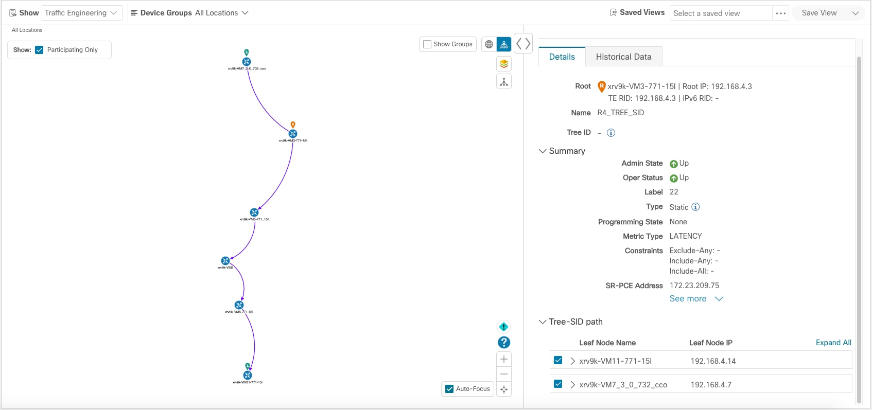
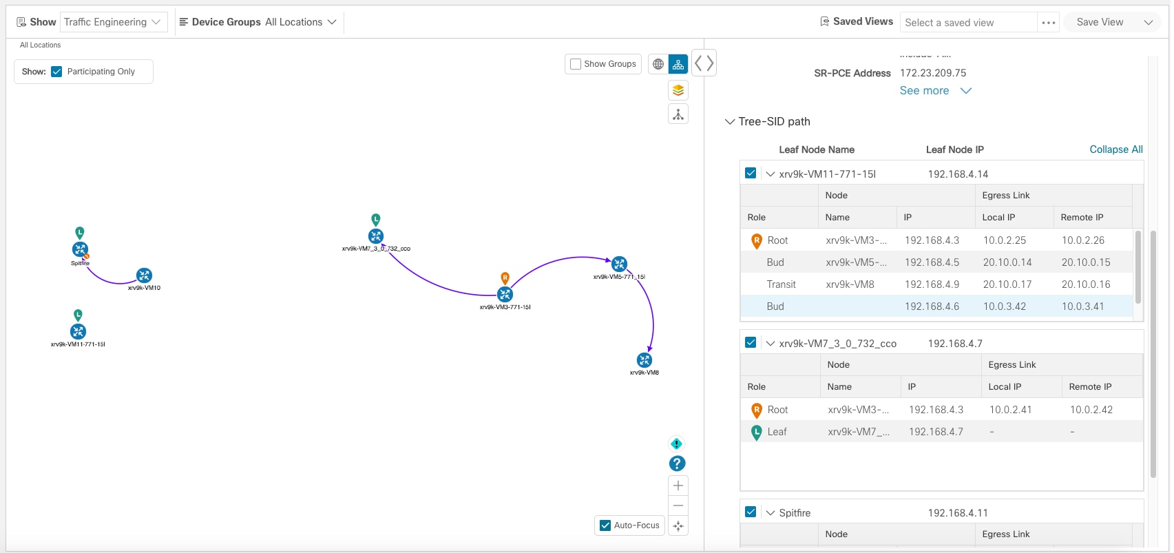
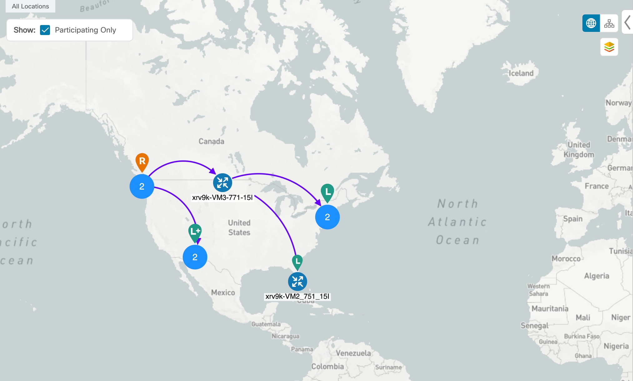
The following example shows a representation of a Tree-SID policy in the Crosswork network map. The root node (R) and leaf nodes (L) are clearly marked, and the arrows denote the path through the transit nodes from the root to the two leaves. Also, bud nodes have a separate leaf node path and are displayed on the Topology map.

You can drill down on the nodes and the links to see more details about the Tree-SID policy and validate the configuration.
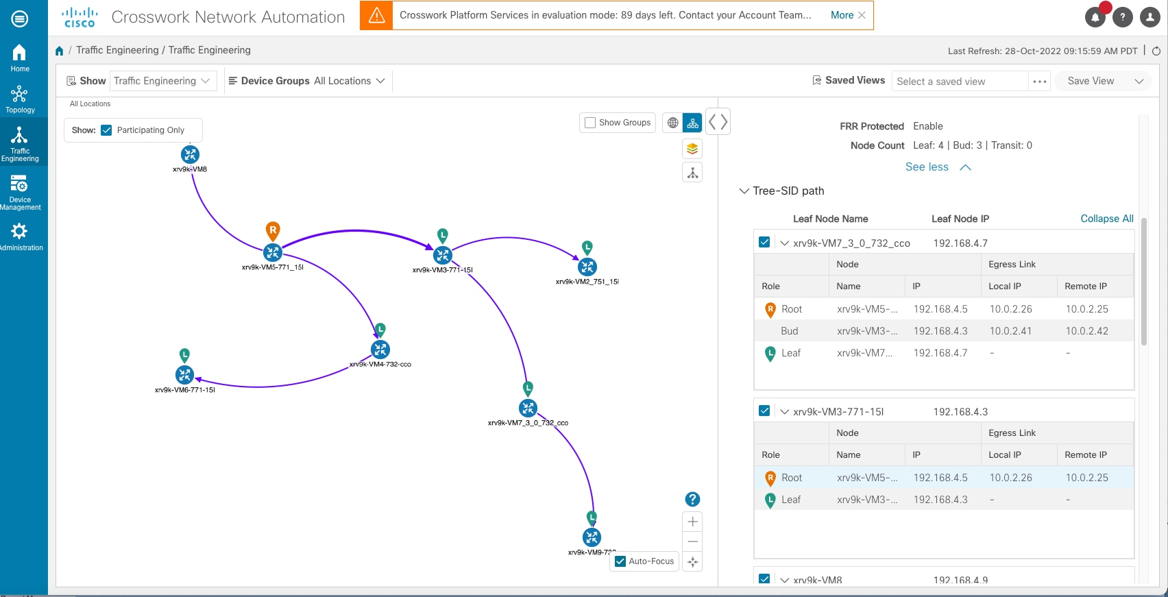
Tree-SID Topology

Before you begin

The following configurations are required for the Tree-SID policy and nodes:

  • Transit node: PCEP is required.

  • Bud node, Egress node, and Ingress node: PCEP, active BGP MVPN session, BGP autodiscovery segment-routing and MDT default segment-routing, MDT partitioned segment-routing

To visualize a multicast tree in the network map, Tree-SID policies must be configured in your network. For more information, see the SR Tree-SID configuration documentation for your specific device (for example: Segment Routing Configuration Guide for Cisco NCS 540 Series Routers).

Procedure


Step 1

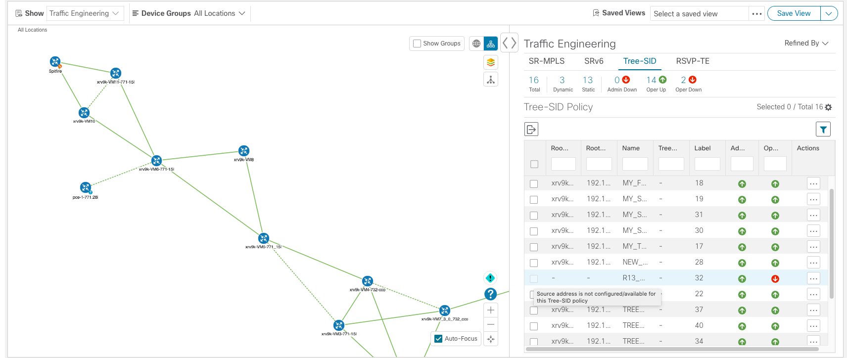
From the main menu, select Traffic Engineering > Traffic Engineering > Tree-SID tab.

Step 2

Select the Tree-SID policies you want to view on the topology map.
Note


You can view a maximum of two policies on the topology map at the same time.

Note


Any change in end-points is captured as an event in the historical data tab. For information on Tree-SID Historical Data see, View TE Event and Utilization History

Step 3

To view the Tree-SID Details, from the Actions column, click Edit icon > View Details for one of the Tree-SID policies.

Step 4

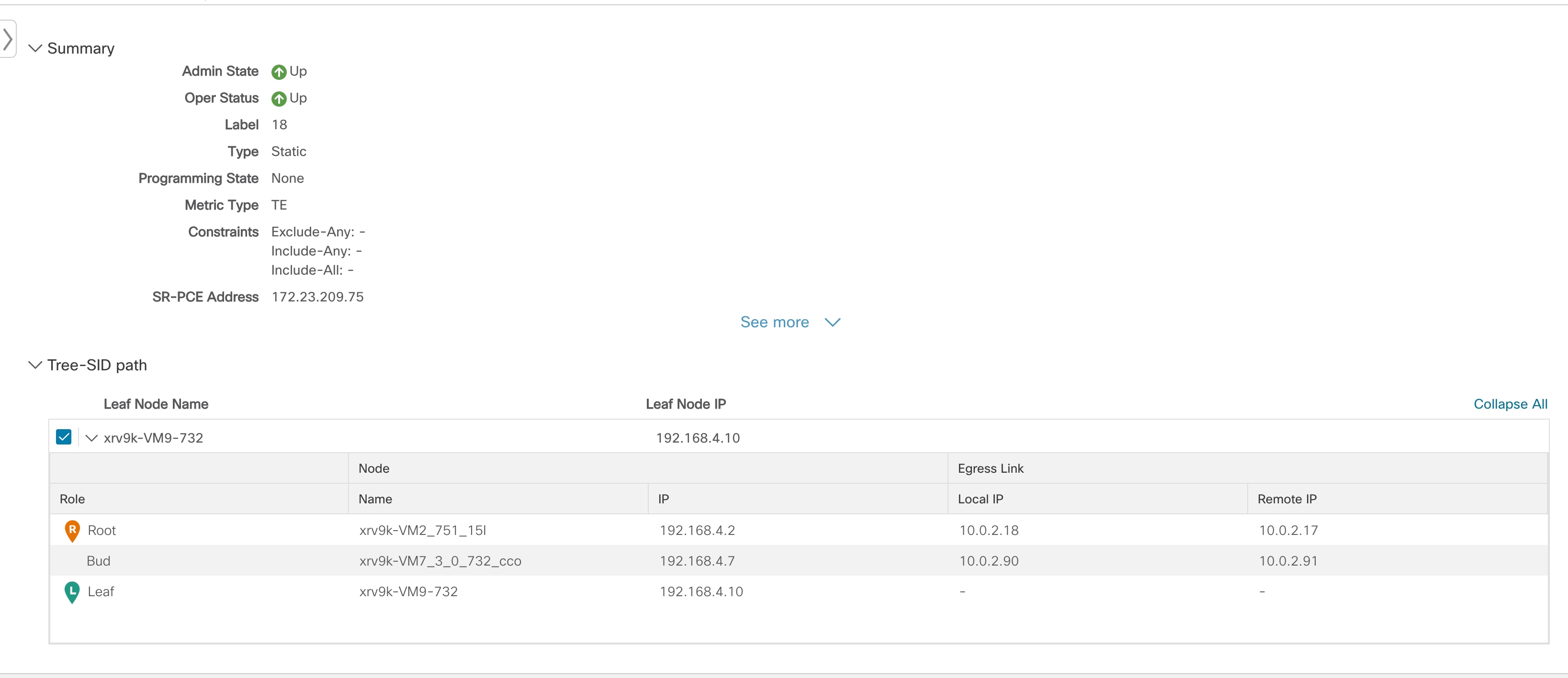
You can view the Tree-SID details, and verify the path and node details to ensure that the Tree-SID is configured correctly.


Limitations for Tree-SID Policies

Limitation

  • Only visualization of Tree-SID policies is supported. You cannot create, edit or delete Tree-SID policies from the UI.

  • Tree-SID policies are only supported on devices running Cisco IOS XR software.

  • Tree-SID policies are not deleted from the UI when the PCE in HA mode is down and also when the PCE is removed from the Crosswork UI.

  • PCE HA is not supported.

  • Tree-SID policies are not supported in Label Switch Multicast (LSM) routing. In cases where LSM is enabled, IGP updates and traffic utilization data are not supported.

  • Tree-SID policy is not created back in PCE, after "no vrf" under pim or "no multicast" on PCC.

  • Ignore the local-hop-address if FRR=true, show value of ‘next-hop-address’.

  • FIB platform update fails on PE routers, when IGP configuration is updated.

  • LCM will not operate in portions of the network carrying Tree-SID LSPs.

  • The RestConf API is not supported.

  • Tree-SID policy details do not show IPv6 router ID or Srv6 core information.

Visualization of Tree-SID Paths with Missing Nodes

Following are the scenarios with missing Tree-SID nodes on the topology:

  • You cannot visualise Tree-SID policy incase the source or root nodes are not configured on the PCE. The details for such Tree-SID policies are not populated, and the policy will be oper-down.

  • You cannot visualize Tree-SID policy path with specific leaf nodes missing. The details for such Tree-SID policies are populated with leaf node path missing. The other Tree-SID paths in the policy are displayed in the network, if any.

  • You can visualize the Tree-SID policy with missing transit or bud node with partial overlay. The details for the Tree-SID policies are populated without the hostname.


    Note


    The below warnings are displayed in case of missing transit or bud nodes:

    1. Historical data tab: Some device links are missing from the policy path because they are not present in the current device inventory and topology database.

    2. Topology UI: Topology map reflects the current state of the network. Current device/link states do not necessarily impact Traffic Engineering policies , tunnels, or services.


  • If the root or source node is removed from the UI, the root hostname will be empty and the Tree-SID policy will be oper-up with no paths available on the topology map. The root router IP is displayed from the earlier Tree-SID discovery.

Tree SID Configuration Example

To visualize Segment Routing Tree-SID, some configurations are required on the SR-PCE and on the devices involved in the Tree-SID paths. Following are some example configurations for each of the steps required in your network:

The following day 0 configuration is required:

Enabling the MVPN address family on all SEPs and on PCE.

Enabling p2mp on PCE.

Static Tree-SID Policy Configuration Example


Note


See Tree-SID configuration documentation for your specific device to view descriptions and supported configuration commands (for example: Segment Routing Configuration Guide for Cisco ASR 9000 Series Routers).


The following steps show examples of Static Tree-SID device configuration:

Procedure


Step 1

Configure the Path Computation Element Protocol (PCEP) and Path Computation Client (PCC) on all nodes involved in the Tree-SID path (root, transit/bud, and leaf).

Example:

pce

 address ipv4 <pce-loopback0-IP>

 api

  user admin

   password encrypted xxxx

  !

 !

 segment-routing

  traffic-eng

   p2mp

    endpoint-set MY_FIRST_TREE_SID_EPs

     ipv4 <leaf or pcc1-loopback0-IP>

     ipv4 <leaf or pcc2-loopback0-IP>

    !

Step 2

Configure P2MP SR static policy on the SR-PCE with end-points.

Example:

policy MY_FIRST_TREE_SID

             source ipv4 <root or pcc3-loopback0-IP>

             color 20 endpoint-set MY_FIRST_TREE_SID_EPs

             treesid mpls 18

             candidate-paths

               preference 100

                dynamic

                 metric

                  type te

        !

       !

      !

     !

    !

Dynamic Tree-SID Policy Configuration Example with VRF

To add more dynamic policies to Tree-SID policy, create VRF on both root and leaf devices. Mention the corresponding VRF, neighbor under BGP router config on PCE, root and leaf devices. VRF under multicast routing, router pim and create route-policy for each different VRFs as mentioned below in examples.

Follow the steps for Dynamic Tree-SID policy:

Pre-req route-policies (configure on both PCE, Root and leaf) devices

Under PCE
route-policy PASS

  pass

end-policy

!
Under Root and Leaf
route-policy bgp_in

  pass

end-policy

!

route-policy PIM-RPF

  set core-tree sr-p2mp

end-policy

!

route-policy bgp_out

  pass

end-policy

!

route-policy PASS_ALL

  pass

end-policy

!

route-policy TREESID-CORE

  set core-tree sr-p2mp

end-policy

!

Procedure


Step 1

Configure under pce→ segment-routing traffic engineering -> p2mp-> label range <>, multi-path disable.

Example:

 label-range min 15400 max 60000

               fast-reroute lfa

               multipath-disable

Step 2

Under router bgp - configure address family ipv4 mvpn at top level and under neighbor node IP <root> and <leaf> level as well with address family ipv4 mvpn.

Example:

 router bgp 1

                   ………..

                   address-family ipv4 mvpn

                   route-reflector-client

                 !

                   neighbor <root or pcc3-loopback0-IP>

                   remote-as 1

                  update-source Loopback0

                  address-family ipv4 unicast

                  route-policy PASS in

                  route-policy PASS out

                !       

                  address-family ipv4 mvpn

              !

             !


             neighbor <leaf or pcc1-loopback0-IP>

                   remote-as 1

                  update-source Loopback0

                  address-family ipv4 unicast

                  route-policy PASS in

                  route-policy PASS out

                !       

                  address-family ipv4 mvpn

              !

             !

Step 3

Configure headend and end-points.

Note


You can add end-point routers as neighbor under PCE → route BGP configuration. Router-IDs need to be updated with each PCC loopbackIP in topology.

  1. Create interface Loopback<80>

    Example:

    interface Loopback80
    
     ipv4 address 80.80.10.1 255.255.255.252
    
     ipv6 address 2001:192:168:80::1/128
    
    !
  2. Create VRF <vrf-name-80>

    Example:

    vrf L3VPN_NM-MVPN-80
    
     address-family ipv4 unicast
    
      import route-target
    
       80:80
    
      !
    
      export route-target
    
       80:80
    
      !
    
     !
    
    !
    
    
  3. Mention <vrf-name-80> under routing BGP configuration

    Example:

    vrf L3VPN_NM-MVPN-80
    
      rd 80:80
    
      address-family ipv4 unicast
    
       redistribute connected
    
      !      
    
      address-family ipv4 mvpn
    
      !
    
      neighbor 80.80.10.1 <leaf or pcc1-vrf-IP>
    
       remote-as 80
    
       address-family ipv4 unicast
    
        route-policy PASS_ALL in
    
        route-policy PASS_ALL out
    
       !
    
      !
    
     !
    
    !
  4. Mention <vrf-name-80> under multicast-routing configuration

    Example:

    multicast-routing
    
     address-family ipv4
    
      interface Loopback0
    
       enable
    
      !
    
      mdt source Loopback0
    
      mdt static segment-routing
    
     !
    
     vrf L3VPN_NM-MVPN-80
    
      address-family ipv4
    
       interface all enable
    
       bgp auto-discovery segment-routing
    
       !
    
       mdt default segment-routing mpls color 80
    
      !
    
     !
    
    !
  5. Create route-policy <vrf-name-80>

    Example:

    route-policy L3VPN_NM-MVPN-80
    
      if destination in (232.0.0.80) then
    
        set on-demand-color 80
    
        pass
    
      endif
    
    end-policy
    
    !
  6. Under segment routing traffic eng -> configure ODN color <80>

    Example:

    on-demand color 80
    
       dynamic
    
        pcep
    
        !
    
        metric
    
         type te
    
        !
    
       !
    
      !


Step 4

Configure Leaf

Note


Follow step a to d to configure headend and endpoint for root nodes.

Example:

router pim

 address-family ipv4

  rpf topology route-policy PIM-RPF

 !

 vrf L3VPN_NM-MVPN-80

  address-family ipv4

   rpf topology route-policy TREESID-CORE

   mdt c-multicast-routing bgp

   !

  !

 !


Dynamic Tree-SID Policy Configuration Example without VRF

To add dynamic policies to Tree-SID policy, without VRF on both root and leaf devices, follow the steps below:


Note


The configuration for PCE are same as for Dynamic Tree-SID with VRF. See Dynamic Tree-SID Policy Configuration Example with VRF


Procedure


Step 1

Configure Root

  1. Mention <leaf-node-IP or pcc1-IP> as neighbor under router BGP configuration.

  2. Mention unique RTs under multicast-routing configuration.

    Note


    The RTs should be unique between Root and Leaf set.

    Example:

    multicast-routing
    
                 address-family ipv4
    
                   import-rt 12:12
    
                   export-rt 12:12
    
                   mdt source Loopback0
    
                   interface all enable
    
                   bgp auto-discovery segment-routing
    
                !
    
                 mdt default segment-routing mpls color 12 fast-reroute lfa
    
                mdt data segment-routing mpls 5 threshold 0
    
            !
  3. Under segment routing traffic eng -> configure ODN color <unique one>.

Step 2

Configure Leaf

  1. Mention <root-node-IP or pcc3-IP> as neighbor under router BGP configuration.

  2. Mention unique RTs under multicast-routing configuration.

    Note


    The RTs should be unique between Root and Leaf set.

    Example:

     multicast-routing
    
                 address-family ipv4
    
                    import-rt 12:12
    
                    export-rt 12:12
    
                    mdt source Loopback0
    
                    interface all enable
    
                    bgp auto-discovery segment-routing
    
                !
    
                 mdt default segment-routing mpls color 12 fast-reroute lfa
    
                mdt data segment-routing mpls 5 threshold 0
    
            !
  3. Configure router PIM, route-policy TREESID_CORE.