Overview
Objective
Network operators need a toolset to help automate bandwidth optimization, steer traffic with little operator intervention, and ensure that critical links always have sufficient bandwidth to avoid congestion.
Challenge
For service providers, managing bandwidth problems used to be a reactive and manual process. Pressure to solve it is huge. Network congestion leads to poor end-customer experiences. Congested links, high latency, and other network impairments lead to a poor perception of the services carried across your network or result in an inability to meet the service level agreements (SLAs) you have with your customers. In the worst-case scenario, your network issues lead to SLA or contract violations and the loss of your brand equity.
Solution
Using Local Congestion Mitigation (LCM) and Circuit Style policies, service providers can now specify business-critical links with the intention of reserving bandwidth for these links. Identifying critical links and the operator's intention enables automatic optimization of the network in real-time.
Crosswork Network Controller offers both:
-
LCM is a tactical solution for bandwidth management and congestion mitigation. It is best applied when attempting to solve congestion issues directly, on the devices themselves, without a full-scale traffic matrix or advanced planning.
-
Circuit-Style Segment Routing (CS-SR) is a strategic traffic engineering solution that permits you to reserve bandwidth in advance for critical links, avoiding congestion issues entirely for these high-priority links.
Local Congestion Mitigation
Instead of optimizing for bandwidth resources in the network by rerouting traffic in the entire network (end-to-end path optimization), LCM checks the capacity locally, in and around the congested area, at an interface level and reroutes traffic between the endpoints of the congested interface (local interface-level optimization). Focusing on an issue locally eliminates the need for simulating edge-to-edge traffic flows in the network through a full traffic matrix, which is both cumbersome and less scalable as node counts continue to increase.
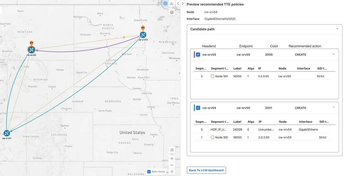
When congestion is detected in the network, LCM provides recommendations to divert the minimum amount of traffic away from the congested interface. LCM collects the SR-TE policy and interface counters through SNMP. It estimates the amount of traffic that may be diverted and, if the user approves, performs the mitigation through the deployment of Tactical Traffic Engineering (TTE) SR-TE policies. Mitigating congestion locally does not require the use of the full Segment Routing Traffic Matrix (SR-TM). TTE SR-TE policies are created at the device on only either side of the congested link, with the shortest paths possible that do not congest interfaces elsewhere.
How does LCM work?
-
First, network operators create domains that define "local" portions of the network. A domain can be the entire network, but more commonly, it matches one or more geographical areas or groups of device interfaces. In this example, we have defined a domain with four devices and all their interfaces. We also assume that all the links in this domain are 1Gpbs.
-
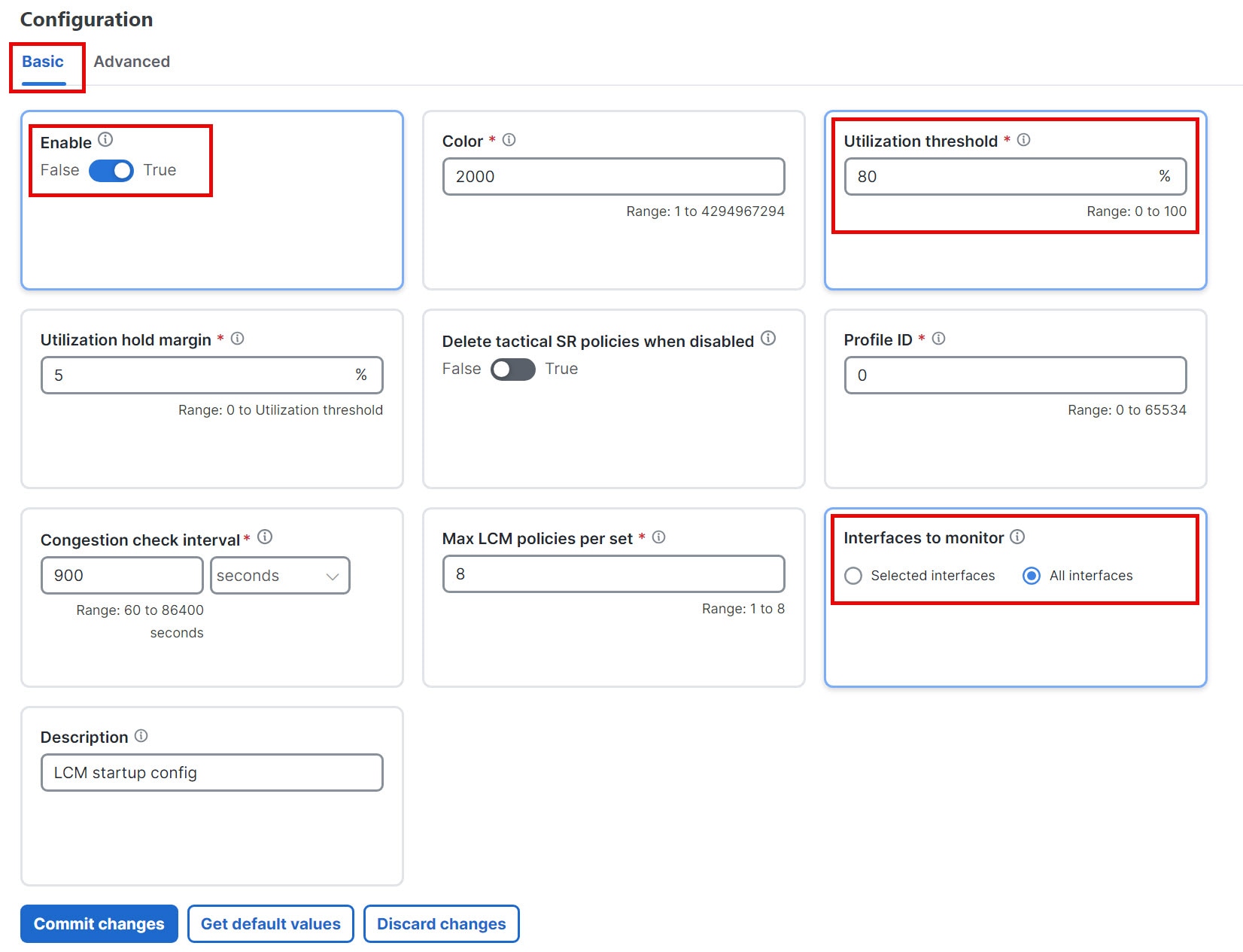
Operator specifies a threshold defining what "congestion" means for a particular domain. In this example, the operator has set the domain's congestion threshold to 70%. The congestion threshold you decide on may vary. For guidance on how to determine what congestion threshold is best for your network and its domain architecture, see Cisco's Local Congestion Mitigation (LCM) White Paper.
-
LCM first analyzes the Optimization Engine Model (a real-time representation of the physical network, topology, and traffic) on a regular cadence. After a congestion check interval, LCM detects congestion when Node 2 utilization goes above the 70% utilization threshold.
Figure 1. How does LCM work? 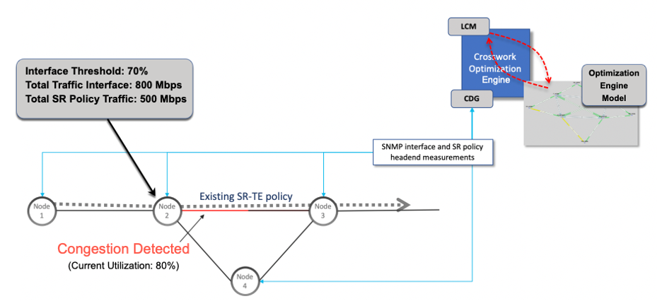
-
LCM calculates how much traffic is eligible to divert. LCM will follow these rules and restrictions in its recommendations:
LCM only diverts traffic that is not already routed by an existing SR policy (for example, unlabeled, IGP-routed, or carried via FlexAlgo-0 SIDs). Traffic within an SR policy will not be included in the LCM calculation and will continue to travel over the original programmed path.
LCM computes diversion-eligible traffic by taking the interface traffic statistics for all traffic on the interface and subtracting the sum of traffic statistics for all SR-TE policies that flow over the interface.
Total interface traffic – SR policy traffic = Eligible traffic that can be optimized
This process must account for any ECMP splitting of SR policies to ensure the proper accounting of SR policy traffic. In this example, the total traffic on congested Node 2 is 800 Mbps and the total traffic of all SR policies routed over Node 2 is 500 Mbps.
The total traffic that LCM can divert in this example is 240 Mbps. That is, 800 Mbps – 560 Mbps = 240 Mbps
-
LCM calculates the amount of traffic that must be sent over alternate paths by subtracting the threshold-equivalent traffic from the total traffic on the interface. In this example, the amount to be diverted is 100 Mbps:
800 Mbps – 640 Mbps (70% threshold) = 100 Mbps
LCM must route 100 Mbps of 300 Mbps (eligible traffic) to another path.
-
LCM determines the number of TTE SR policies are needed and their paths. The ratio of how much LCM eligible traffic can stay on the shortest path to the amount that must be rerouted, will determine the number of TTE SR policies needed on the shortest and alternate paths, respectively.
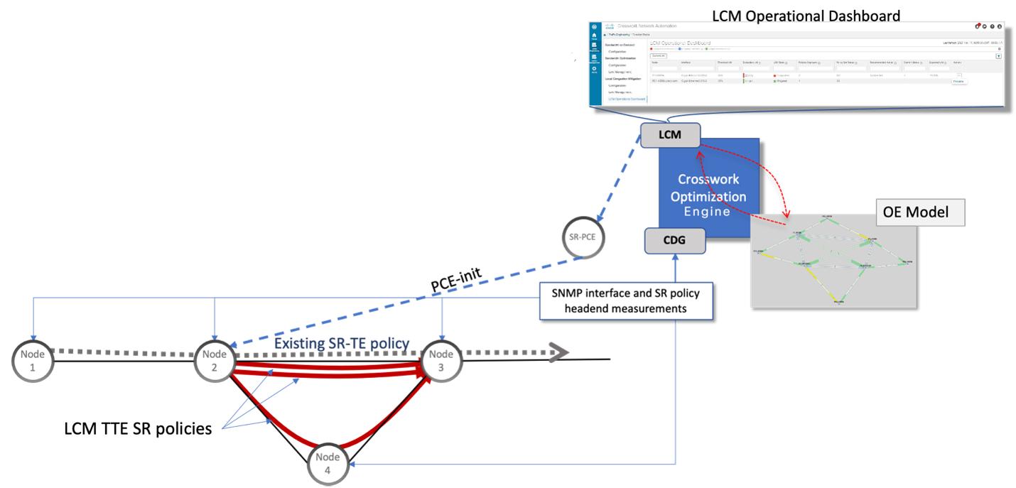
In this example, LCM must divert one-third of the total eligible traffic (100 Mbps out of 300 Mbps) away from the congested link. Assuming a perfect ECMP, LCM estimates three tactical SR-TE policies are required to create this traffic split: one tactical SR-TE policy will take the diversion path, and two tactical SR-TE policies will take the original path. There is sufficient capacity in the path between Node 2 and Node 4. Therefore, LCM recommends three TTE SR policies (each expected to route approximately 100 Mbps) to be deployed from Node 2 to Node 3 via SR-PCE:
-
2 TTE SR policies to take a direct path to Node 3 (200 Mbps)
-
1 TTE SR policy takes a path via Node 4 (100 Mbps)
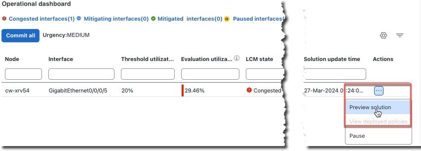
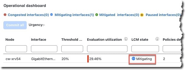
These recommendations will be listed in the LCM Operational Dashboard.
-
Assuming you deploy these TTE SR policies, LCM continues to monitor the deployed TTE policies and will recommend modifications or deletions as needed in the LCM Operational Dashboard. TTE SR policy removal recommendations will occur if the mitigated interface is not congested if these policies are removed (minus a hold margin). This helps to avoid unnecessary TTE SR policy churn throughout the LCM operation.
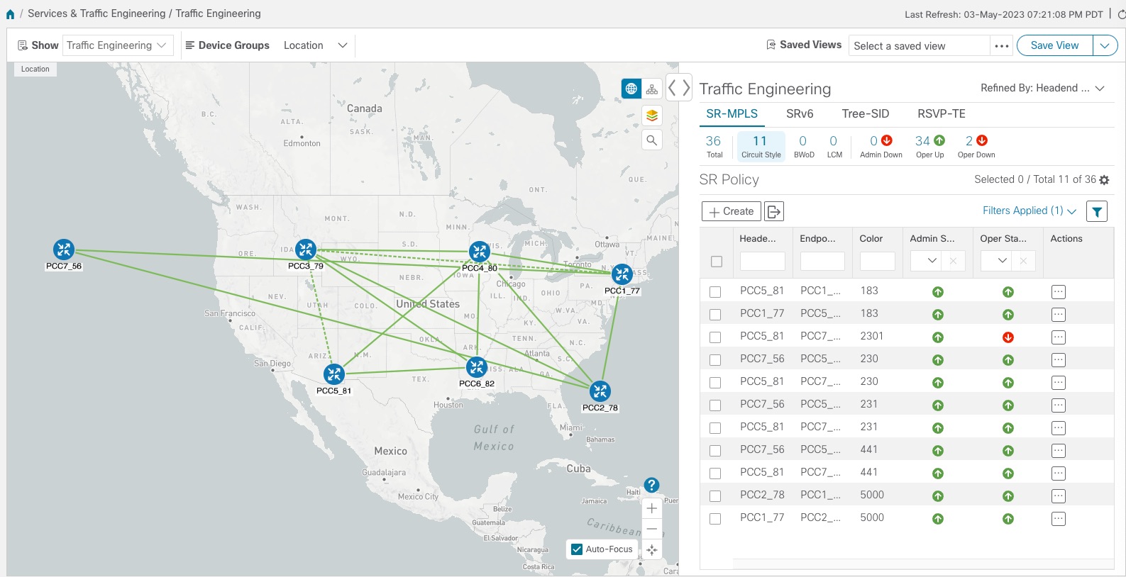
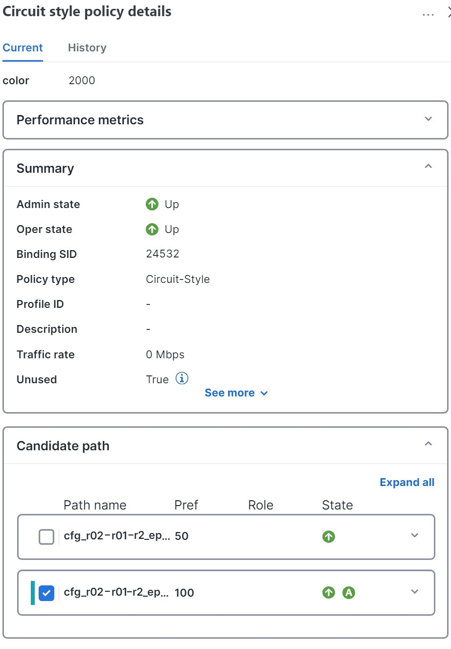
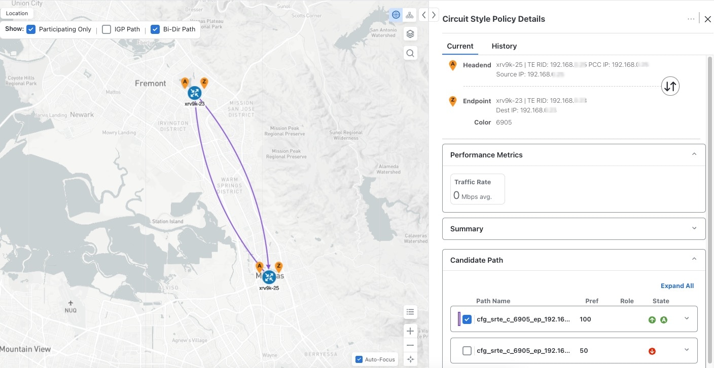
Circuit-Style policies
Circuit-Style Segment Routing Policies (CS-SR or CS policies) are connection-oriented transport services that you can use to implement what are sometimes referred to as "circuit emulations" or "private lines". Combining segment-routing architecture's adjacency SIDs with stateful PCEP path computation, CS policies provide:
-
Persistent, dedicated, bi-directional, co-routed transport paths with predictable latencies and other performance metrics in both directions.
-
Guaranteed bandwidth commitments for traffic-engineered services using these paths.
-
End-to-end path protection to ensure there is no impact on Service Level Agreements.
-
Automatic monitoring, maintenance, and restoration of path integrity.
-
Flexible operations, administration, and management of CS paths.
-
A software-defined replacement for older CEM infrastructure, such as SONET/SDH.
How do Circuit-Style policies work?
The initial configuration of CS policies follows these steps:
-
Crosswork Network Controller and its applications discover and map the network topology.
-
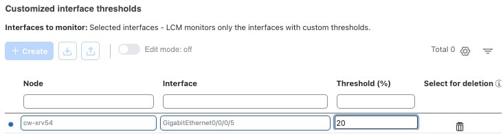
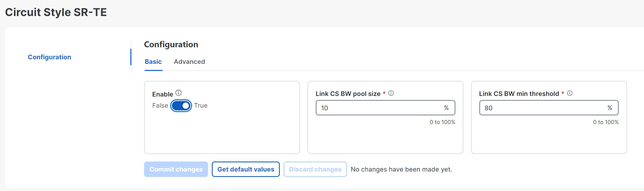
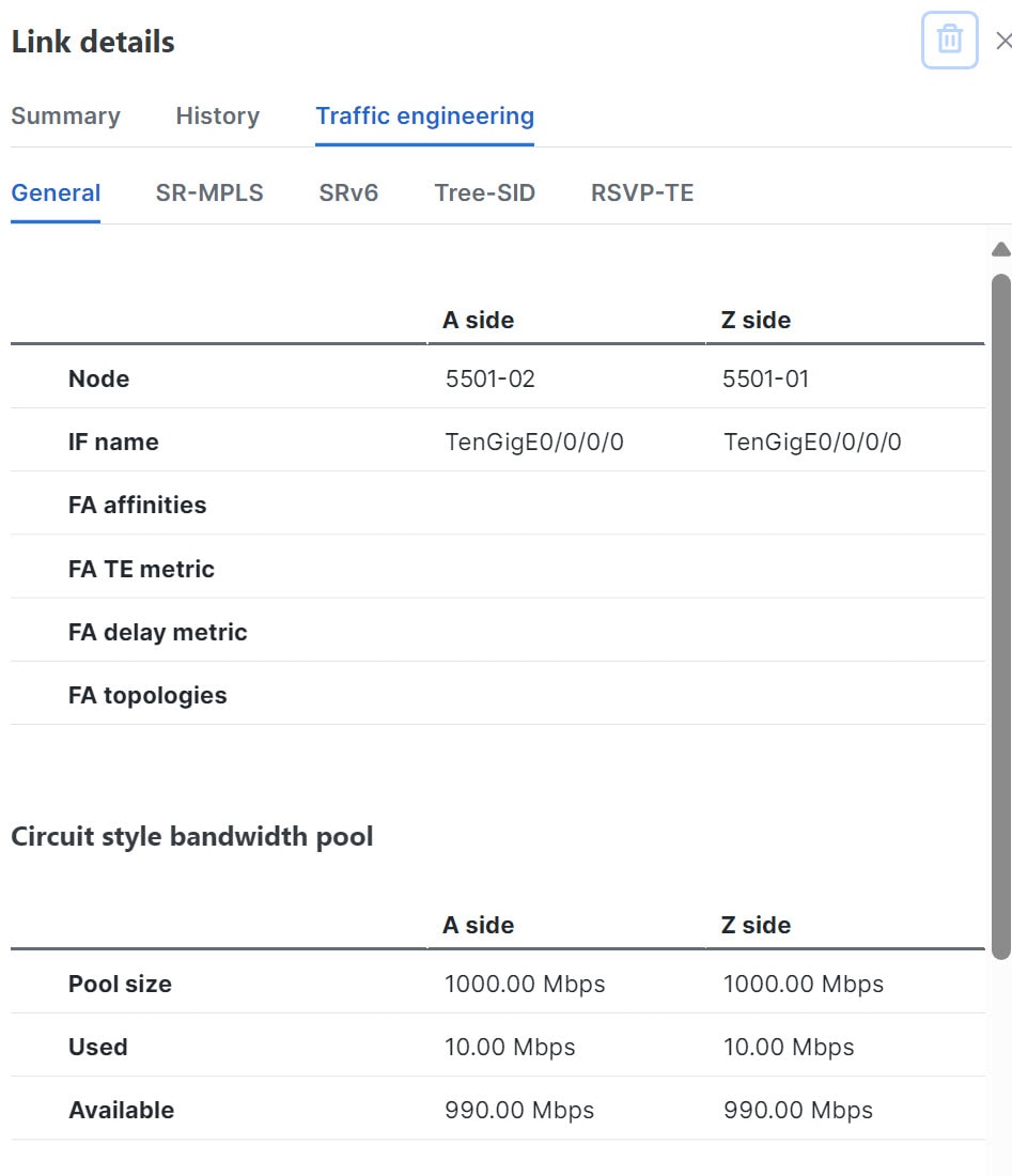
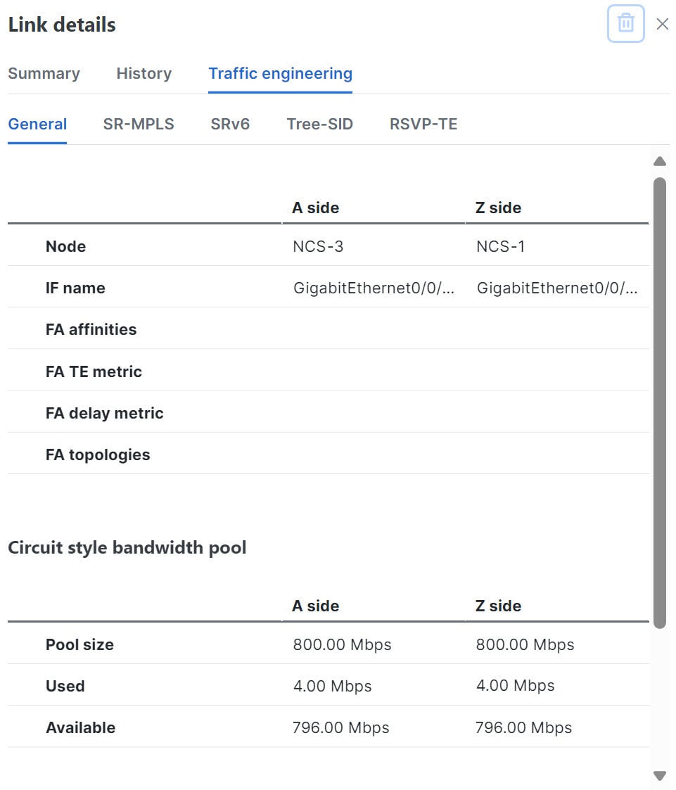
Crosswork Network Controller users enable CS policy support, specifying the base bandwidth to be allocated to CS policies as a whole and a threshold percentage of bandwidth usage that will generate an alarm when exceeded on any CS-calculated path. So, for example, on a 1 GB link with 20 percent of bandwidth reserved for CS use, CS policies can use up to 200 Mbps of that link. Note, however, that if the bandwidth minimum threshold is set to the default of 80 percent, alarms will be generated as soon as 160 Mbps of the link is used.
-
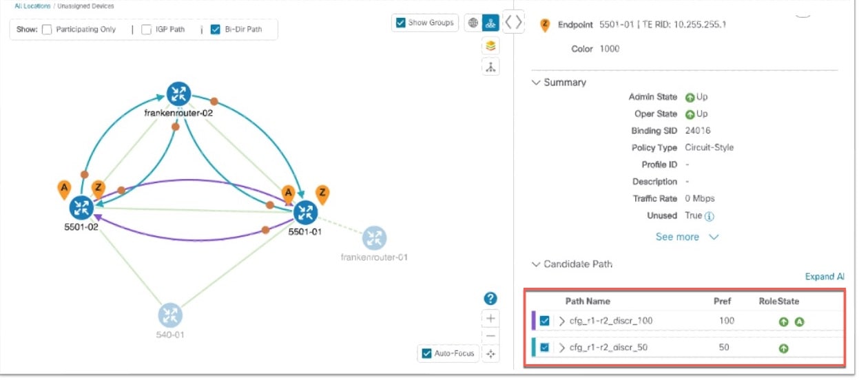
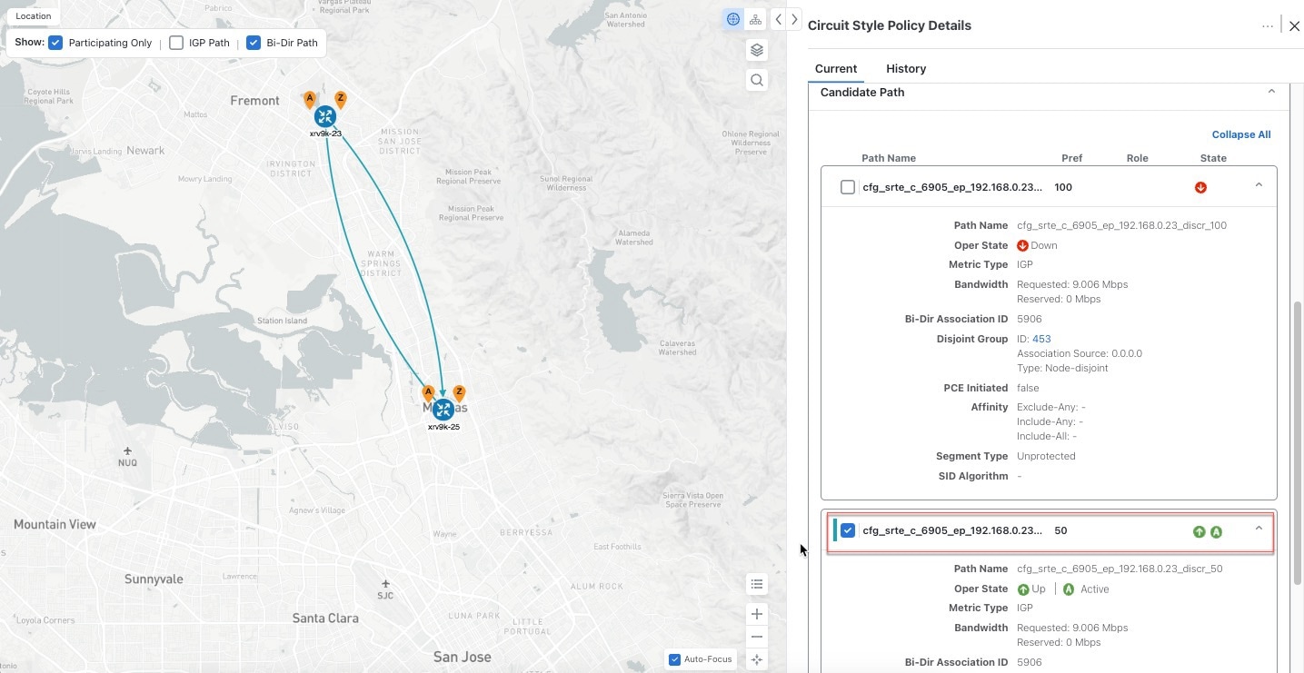
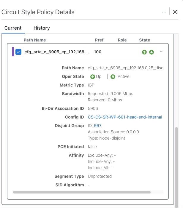
Network operators create a CS policy for each set of nodes for which they want to establish a guaranteed path. The policy specifies the two nodes to be linked by the main path, the bandwidth to be reserved, and the backup path. To accommodate bandwidth and path failures, the configuration must include bi-directionality, path protection, and performance-management liveness-detection settings.
-
When the operator commits the CS policy, the device-resident Path Computation Client (PCC) will request the Crosswork-resident PCE server to compute candidate Working and Protected paths that conform to the CS policy's bandwidth and other constraints (using a single PCEP request message).
-
When CS policy support is enabled, the PCC computes both paths and deducts their CS policy-guaranteed bandwidth from the allocated available bandwidth.
-
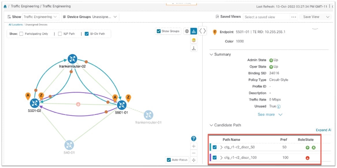
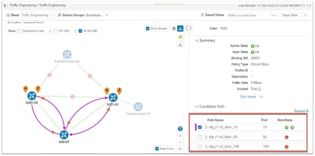
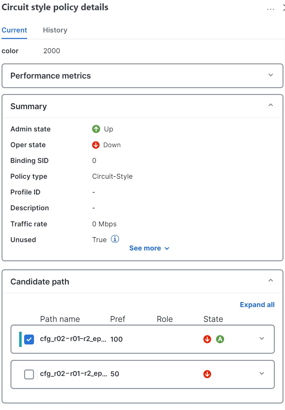
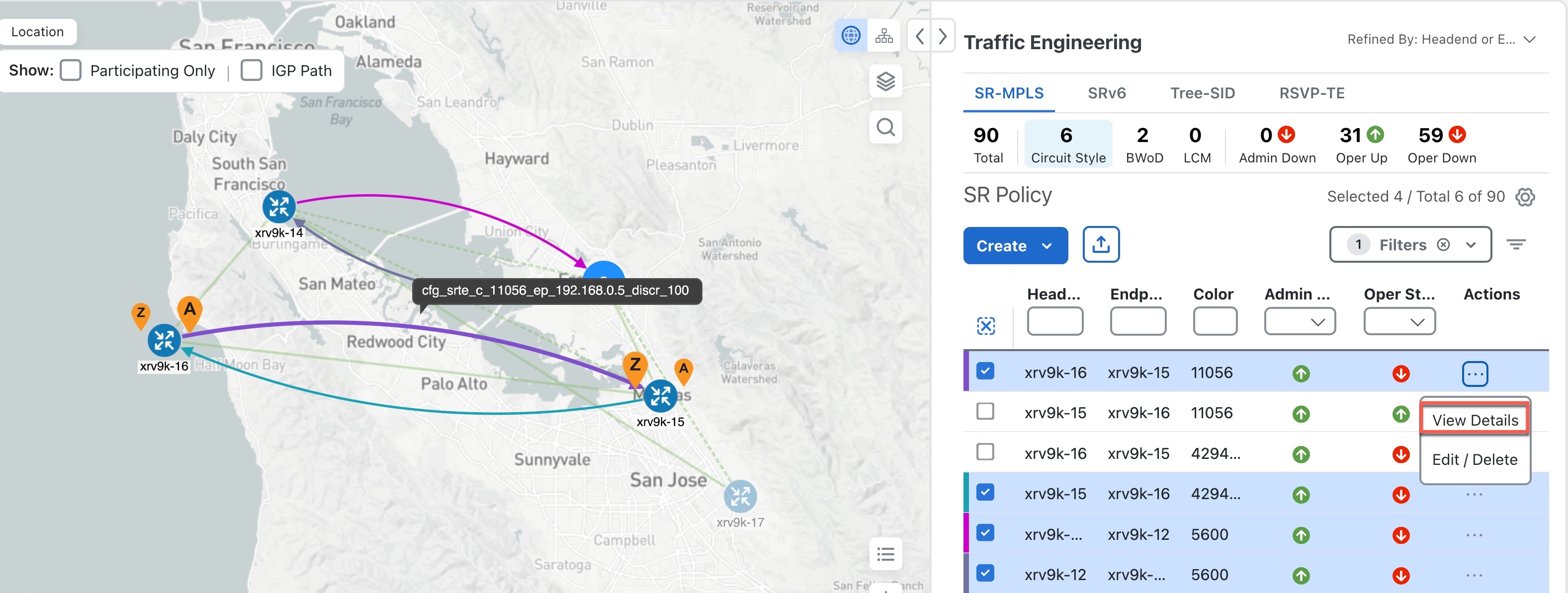
Crosswork Network Controller replies to the PCC with the primary Working and Protected path lists and commits to, or "delegates," them. The topology map displays the current Active and Protected paths between the two nodes, using the colors configured when the CS policy was configured, and labels the two endpoint nodes so they can be identified as CS policy endpoints.
After the initial configuration:
-
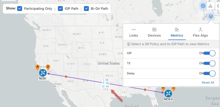
Crosswork Network Controller monitors the delegated path and the active CS policies. It updates the available and reservable bandwidth in the network in near real-time.
-
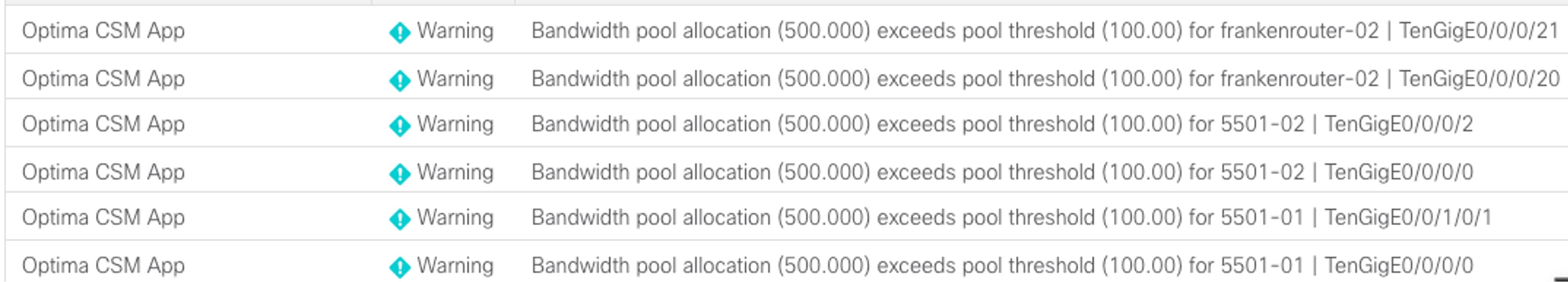
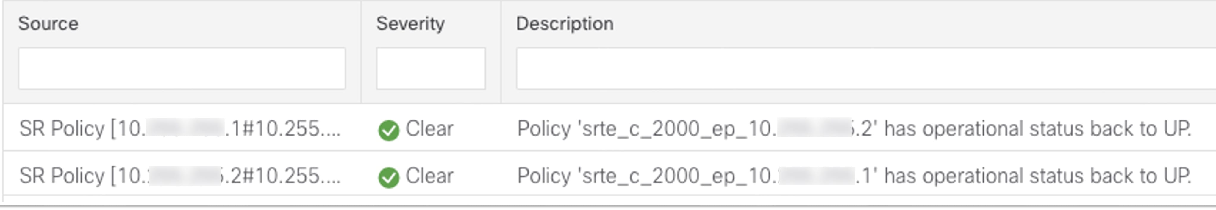
Crosswork Network Controller generates threshold-crossing alarms when bandwidth usage or additional CS policy requirements exceed the configured reserved bandwidth or bandwidth usage threshold.
-
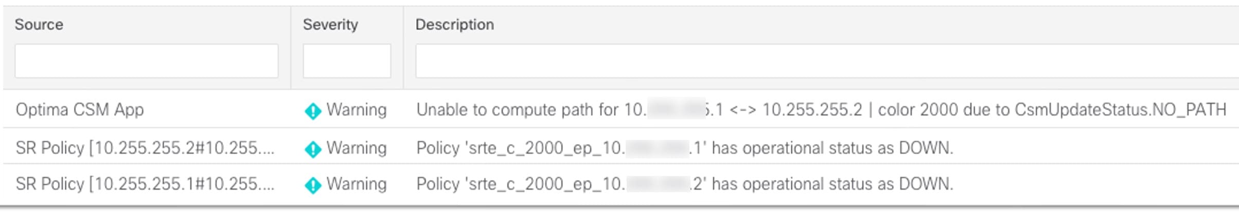
If delegated paths fail for any reason, Crosswork Network Controller recomputes paths as needed.


 Feedback