Local Congestion Mitigation (LCM) White Paper
Available Languages
Bias-Free Language
The documentation set for this product strives to use bias-free language. For the purposes of this documentation set, bias-free is defined as language that does not imply discrimination based on age, disability, gender, racial identity, ethnic identity, sexual orientation, socioeconomic status, and intersectionality. Exceptions may be present in the documentation due to language that is hardcoded in the user interfaces of the product software, language used based on RFP documentation, or language that is used by a referenced third-party product. Learn more about how Cisco is using Inclusive Language.
Service providers perform capacity management as part of the network design, implementation, and operation lifecycle. Capacity management encompasses three processes that provide a holistic approach to building and running a network efficiently.
A Holistic Approach
● Encompasses three processes – Solves different problems over different timeframes.
Table 1. Common processes performed by network operators as part of capacity management
|
|
Network Engineering |
Capacity Planning |
Traffic Engineering |
| Timeframe |
Long-term |
Medium-term |
Short-term |
| Problem Statement |
Build your network capacity where you think your traffic will be in the future |
Add network capacity where you think you will run out |
Routing traffic where network capacity is |
| Inputs |
Traffic demand matrix |
Physical topology and projected growth, per flow demand matrix |
Physical topology, optimizable and non-optimizable traffic |
| Objective |
What is most effectively physical topology |
How much capacity (and where) is required to support growth |
How to achieve most efficient routing of demands |
| Complexity |
Low |
Medium |
High |
Network engineering tries to solve the problem of building out network capacity where traffic will be in the foreseeable future. It requires insights into customer traffic patterns and uses heuristics to project where and when to build these capacities. Considering viability and cost of procuring circuits and resiliency against failures, this process aims to come up with the most effective physical topology.
Capacity planning is performed on an ongoing basis based on current network utilization and projected traffic growth. Using the current topology and data from trending analysis and knowledge of any future events that may drive demand, capacity planning provides the operator with information on how much capacity to add and at which part of the network to support the projected growth.
Comparatively, traffic engineering is a shorter-term approach to the capacity management problem in which an operator tries to route traffic to where capacity is currently available, thereby making efficient use of the network. Traffic engineering is traditionally performed using a manual workflow by customers periodically (for example, twice a day), on an ongoing basis.
The Cisco® WAN Automation Engine (Cisco WAE) has traditionally been used to assist operators in all three aspects of the capacity management process performed as part of offline planning. The Cisco Crosswork™ Optimization Engine is an enabler for real-time optimization use cases. With the introduction of Local Congestion Mitigation (LCM), Crosswork Optimization Engine provides operators with an additional toolset to address traffic engineering requirements as well as transient congestion by identifying and optionally diverting traffic to where capacity is available. Working hand in hand with Quality of Service (QoS) and capacity planning, it aims to provide a scalable and straightforward method for mitigating congestion locally through the deployment of tactical Segment Routing Traffic Engineering (SR-TE) policies.
LCM does not replace the need for proper network engineering and capacity planning. Having a well-engineered network that is resilient to failures is a prerequisite for using LCM. This ensures adequate capacity and path diversity in the event of network failures.
LCM is designed to temporarily bridge customers' gaps when traffic levels have exceeded their predicted/planned levels due to transient increases in traffic or short term network failures. This allows time for additional offline edge-to-edge traffic engineering and capacity planning/optimizations which may be performed using the WAN Automation Engine. LCM is not designed to react to congestion events in real-time to protect high-priority traffic, which is a task better suited by the proper implementation of QoS on the network. The effective implementation of LCM assumes that there will only be a small number of interfaces that are congested at any time, and that there is sufficient capacity on alternate path links for the diversion of traffic off the congested interfaces.
The main benefit of the approach adopted by LCM is in its design to be simple and scalable. The requirements on instrumentation on network elements are kept to a minimum. This translates to lower complexity and broader applicability of the solution across various customer deployment scenarios. LCM may also be operated in monitor mode, allowing it to be used as a tool for identifying transient sources of congestion and their potential solutions.
LCM's approach is to try to identify and find a solution to the congestion problem by diverting the minimal amount of traffic away from the congested interface to bring it out of congestion. LCM performs the collection of SR-TE policy and interface counters. It estimates the amount of traffic that may be diverted and, if the user approves, performs the diversion/mitigation through the deployment of tactical SR-TE policies.
LCM’s approach differs from the current Bandwidth Optimization (BWOpt) Feature Pack implementation in various aspects. It does not require the use of the Segment Routing Traffic Matrix (SR-TM) and creates tactical SR-TE policies only between devices on either side of the congested link. LCM relies on schedule-based (≥10-min) congestion detection and is suitably positioned for scheduled mitigation (for example, augmenting hourly or twice daily optimizations that customers perform using a manual workflow) instead of an event-based system implemented in BWOpt. Note that the initial release of LCM requires a human-in-the-loop in its current form, which is more appropriate for scheduled mitigations on a longer timescale.
Optimizable and nonoptimizable traffic
In LCM, only traffic that is not carried by SR-TE policies (for example, unlabeled, IGP routed, or carried via FlexAlgo-0 SIDs) is eligible to be diverted or steered via LCM tactical SR-TE policies. In a customer network, this may be traffic that is best effort or low priority. Traffic that is being carried on existing SR policies, or carried on strict-SPF SIDs or adjacency SIDs or Flex Algo, will continue to travel over the original programmed path. By a similar token, RSVP-TE traffic, if it exists, will be considered under the nonoptimizable traffic bucket. In the initial implementation, steering is performed using autoroute include-all to divert traffic to the alternate path.
One may optionally use Policy-Based Tunnel Selection (PBTS) and MPLS EXP to steer optimizable traffic in a more flexible way from all traffic outside of an existing policy.
Note that the initial implementation of LCM does not perform the following:
● Move traffic belonging to existing SR policies to LCM tactical SR-TE policies
● Modify the path of existing deployed SR-TE policies in order to mitigate congestion
The same rules above also apply for RSVP-TE tunnels.
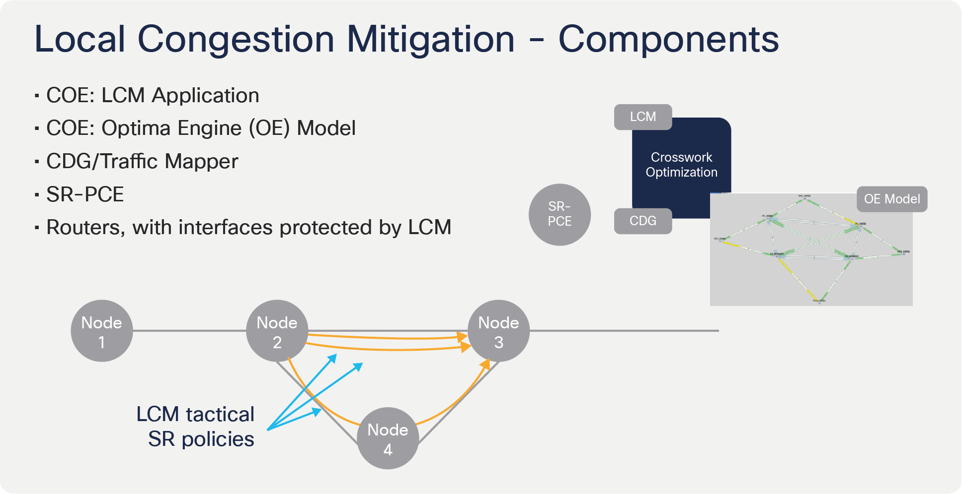
The LCM solution is composed of the following components:
● LCM Application – The LCM application is a functional component shipped with the Crosswork Optimization Engine. It may be enabled/disabled as desired by the operator. The LCM Application provides a Configuration, Link Management, and Operational Dashboard within the Optimization Feature Pack menu of the Crosswork Optimization Engine UI. RESTCONF APIs are available for LCM configuration.
● Optimization Engine (OE) Model – Crosswork Optimization Engine maintains a representation of the physical network using a real-time network model. This real-time model includes topology and traffic information and is the basis for LCM algorithms to execute against, detect, and attempt to find a solution to the congestion problem.
● CDG/Traffic Mapper – The Crosswork Data Gateway (CDG) performs statistics collection, reaching out to the network elements to retrieve information on interface and SR-TE policy utilization. The traffic mapper allows the correlation of the collected information with the network elements and the Optimization Engine (OE) model to be updated.
● SR-PCE – The Segment Routing Path Computation Element (SR-PCE) performs real-time topology collection through the use of BGP-Link State (BGP-LS), or by participating directly in the network’s Interior Gateway Protocol (IGP). In addition, it collects information on deployed SR-TE policies and may be used to deploy LCM tactical SR-TE policies through the use of the Path Computation Element Communication protocol (PCEP).
● Routers, with interfaces protected by LCM – These are routers in the topology whose interfaces are to be monitored and protected against congestion. LCM supports the use of a global and per-link congestion thresholds. These thresholds may be used as a means to exclude links eligible for consideration in LCM computation.
Local Congestion Mitigation - Key components
A typical Local Congestion Mitigation (LCM) workflow is composed of the following:
● Congestion Detection – In the congestion detection phase, the Crosswork Optimization Engine network model is updated with interface and edge SR-TE policy statistics at a regular cadence. LCM analyses the model and determines which interfaces are congested by comparing the measured utilization against the interface threshold.
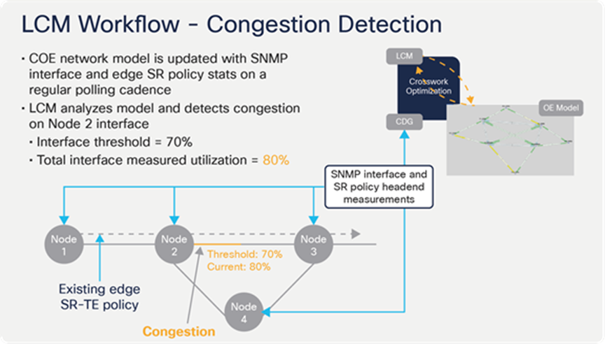
LCM congestion detection
● Estimating Optimizable Traffic – LCM will attempt to estimate the amount of traffic on the congested interface, which is eligible for steering onto LCM tactical SR-TE policies. This is done by collecting the interface statistics on the device with the congested interface and headend SR-TE statistics and policy path information. LCM can then estimate how much traffic on the congested interface originates from SR-TE policies and determines the total amount of traffic that needs to be diverted off the congested interface.
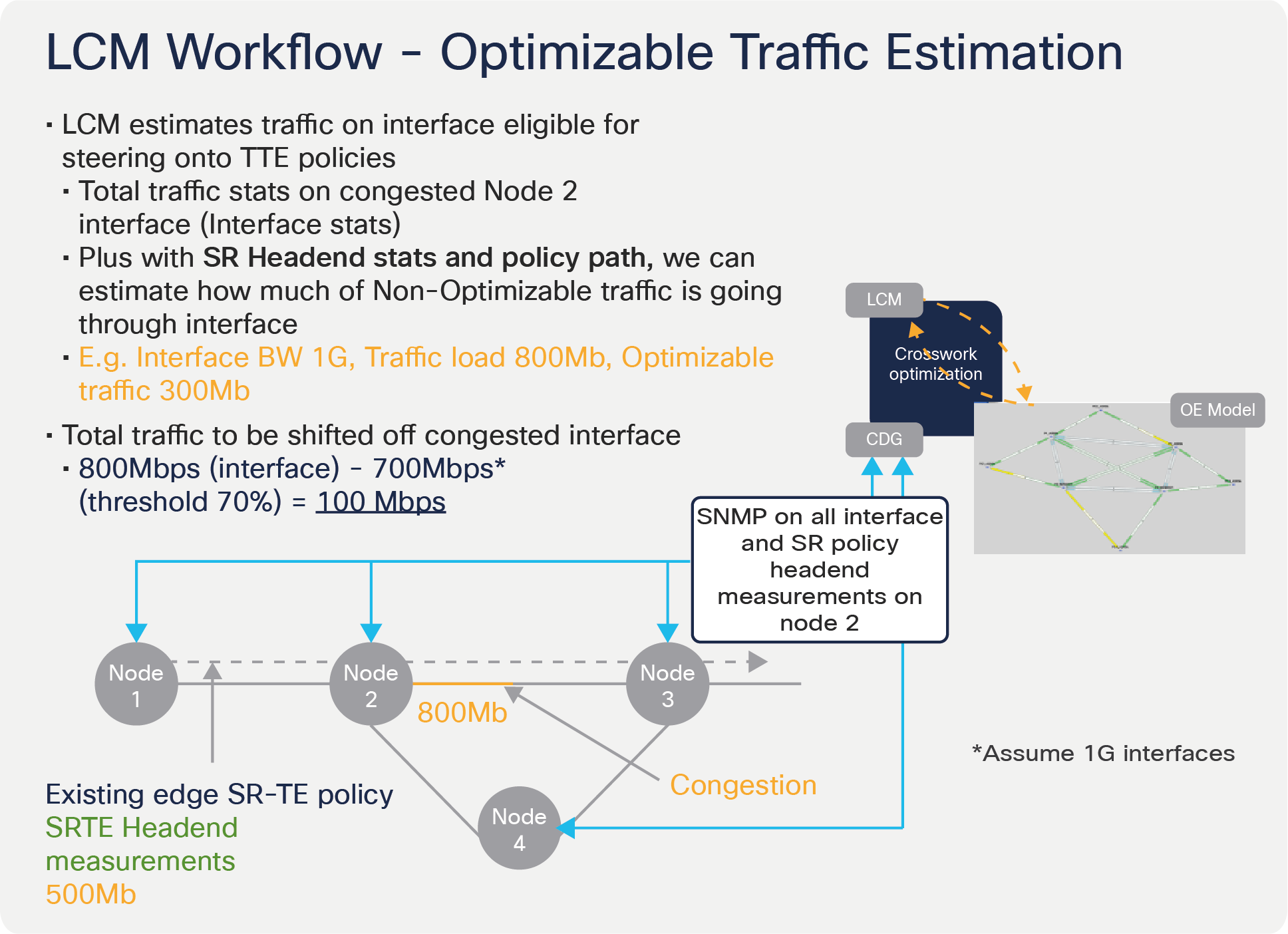
LCM estimating traffic which may be optimized during congestion
● LCM Tactical SR-TE Policy Path Computation – At this stage, LCM has determined the minimal amount of traffic that must be diverted to bring the monitored interface out of congestion. It determines which alternate paths have sufficient capacity and recommends the deployment of multiple parallel SR-TE policies on the device with the congested interface. LCM leverages on Equal Cost Multi-Path (ECMP) on PCE-initiated SR-TE policies using autoroute steering to divert the minimum amount of traffic to the alternate path by having some of these tactical SR-TE policies go over the original traffic path. CDG will collect interface and SR-TE policy statistics on the device with the congested interface, allowing LCM to monitor the actual traffic on both the original and diversion path, thereby providing for further adjustments to be made in the next run of the LCM algorithm.
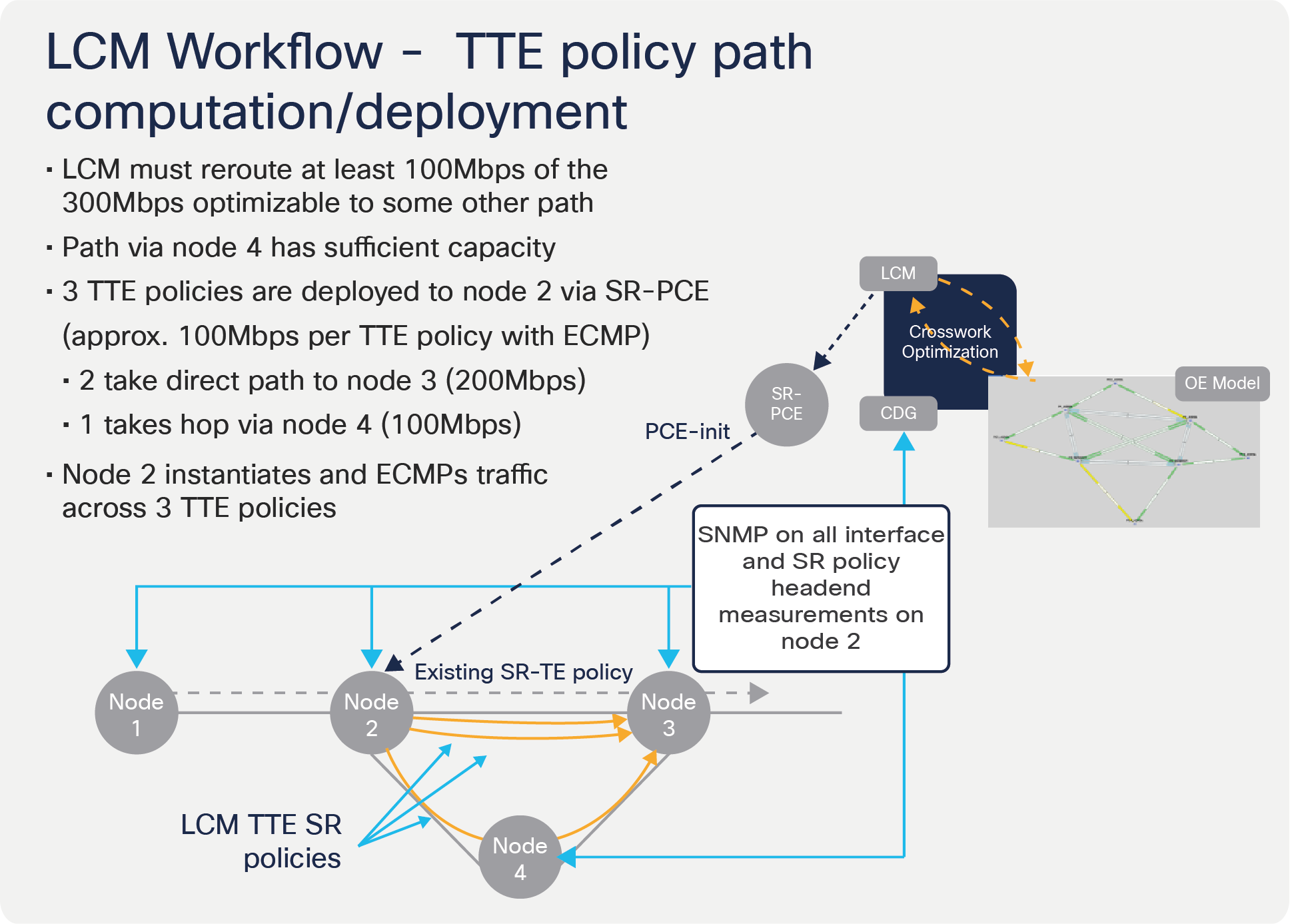
LCM tactical SR-TE policy path calculation and deployment
● Tactical SR-TE Policy – LCM continues to manage the deployed tactical SR-TE policies and recommend modifications or deletions if congestion reoccurs. The tactical SR-TE policies will be recommended for removal if the mitigated interface would not be congested if these policies were removed, minus a hold margin. This helps to avoid unnecessary tactical SR-TE policy churn throughout the LCM operation.
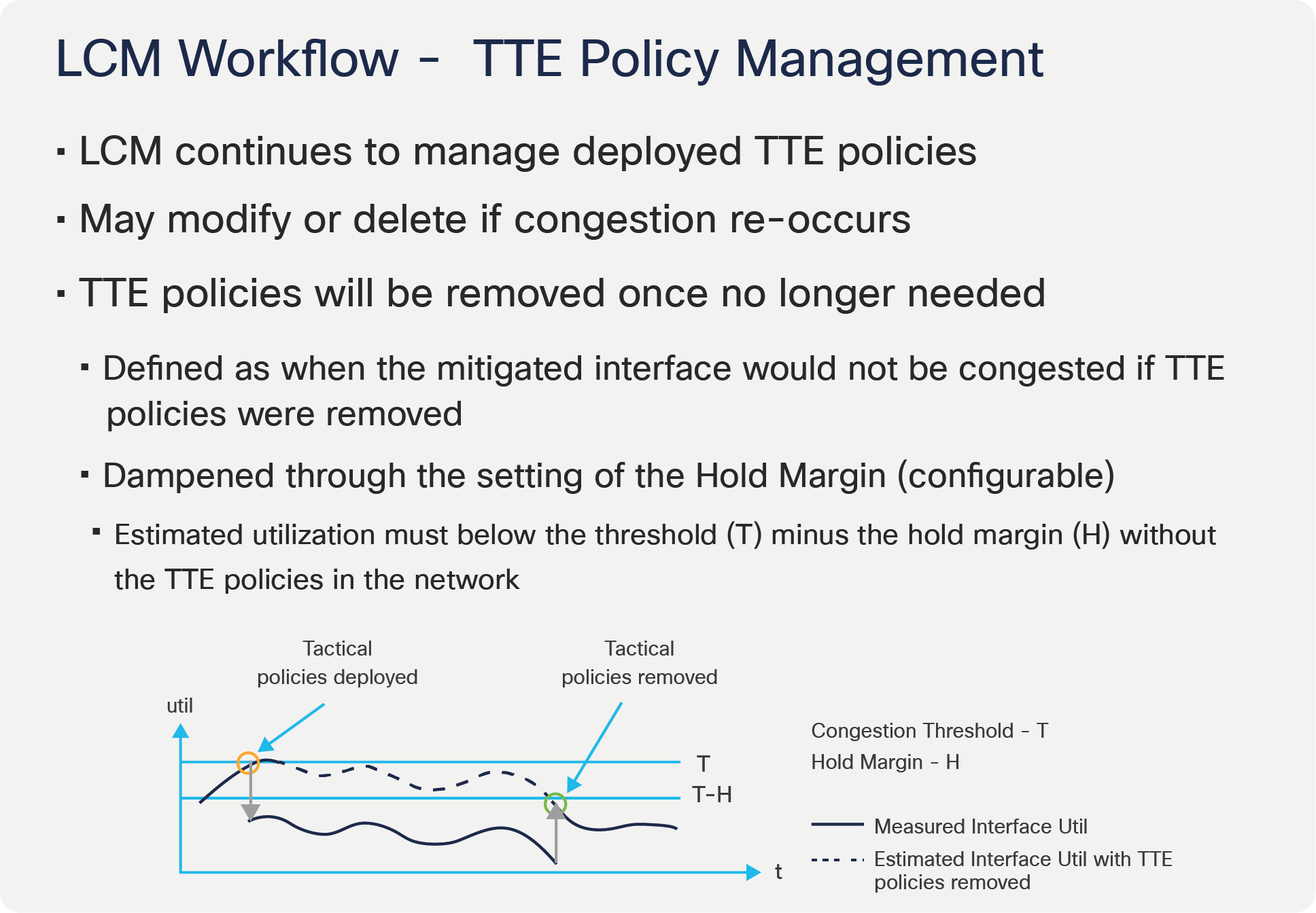
LCM tactical SR-TE policy management
One of the cornerstones in LCM’s design is to minimize instrumentation requirements on the network devices. The intent is to allow maximum applicability of the solution across a wide range of network devices for multiple vendors. The following is a nonexhaustive list of high-level requirements for proper LCM operation:
Congestion Evaluation:
● LCM requires traffic statistics from the following:
◦ Interface traffic measurements
◦ Headend SR-TE policy traffic measurements
● LCM evaluates network utilization on a regular cadence. This cadence can be configured but must be greater than or equal to the collection cadence (typically five minutes or more).
Congestion Mitigation:
● Headend device must support PCE-initiated SR-TE policies with autoroute steering
● Headend device must support Equal Cost Multi-Path (ECMP) across multiple parallel SR-TE policies
As an example, the Cisco ASR 9000 is a platform that fulfills all requirements and is slated to be supported in COE 2.0. For more information, please contact your Cisco account representative.
LCM, in its current implementation, provides an operational dashboard that is used as part of the LCM operational workflow. The LCM dashboard presents the user with a list of detected congested interfaces, LCM tactical SR-TE policy recommendations, and the predicted interface utilization with these policies deployed.
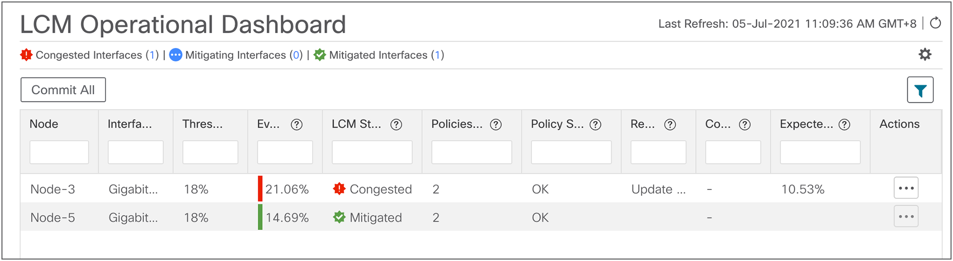
LCM Operational dashboard showing congested/mitigated interfaces and recommendations
In addition, the user may choose to preview the recommended tactical SR-TE policies. The user must select “Commit All” to commit these LCM tactical SR-TE policies to the network.
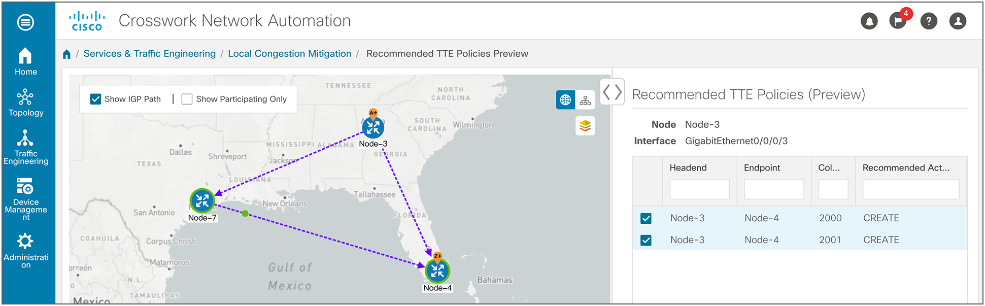
LCM previewing recommended SR-TE policy prior to user commit
Alternatively, the user may choose to adopt LCM operating in monitoring mode and not perform any commits. This allows a phased approach to LCM deployment, for the operator to better understand LCM before performing any mitigation action.
Local Congestion Mitigation (LCM) is designed to be a simple and scalable solution to provide service providers with a toolset for congestion mitigation. It complements existing QoS implementation and capacity planning in order to achieve this goal.
Appendix A. LCM configuration parameters
| Name |
Default |
Description |
|
| Basic |
Enable |
False |
Enable LCM Feature Pack. |
| Advanced |
Optimization objective |
Minimize the IGP metric |
Path computation objective used for tactical SR policies. |
| Basic |
Color |
2000 |
LCM will assign color values to tactical SR policies incrementally starting at this value. [1, 4294967295] |
| Basic |
Utilization threshold |
100 |
The percent utilization at which LCM will consider an interface to be congested. Overridden by Link Management entries. [0, 100] |
| Basic |
Utilization hold margin |
5 |
Tactical policies are removed only if the utilization of the mitigated interface without them will be this amount below utilization threshold. Dampens removals. [0, utilization threshold] |
| Basic |
Delete tactical SR policies when disabled |
False |
Delete all deployed tactical SR policies when LCM is disabled. |
| Basic |
Profile ID |
0 |
Profile ID to assign all tactical SR policies. Should be mapped to autoroute feature on PCCs. 0 means unset. [0, 65535] |
| Basic |
Congestion check interval |
900 |
LCM evaluates the network for congestion at this interval (seconds). [600, 86400] |
| Advanced |
Congestion check suspension interval |
600 |
The minimum duration in seconds after any tactical SR policy create/update/delete to suspend congestion detection/mitigation and allow model convergence. [600, 3600] |
| Advanced |
Deployment timeout |
180 |
Max time in seconds to allow deployment of tactical SR policies to be confirmed. [10, 300] |
| Advanced |
Debug optimizer |
False |
Save debug plan files to file system. |
| Advanced |
Debug opt max plan files |
30 |
The max number of debug plan file sets to save. 0 means no max. [0, 1024] |
| Basic |
Max LCM policies per set |
8 |
Max number of tactical policies used to mitigate a single interface. [1, 8] |
| Basic |
Include all interfaces |
False |
If set to false, only interfaces defined in Link Management can be mitigated. If true, all interfaces. |