Overview
Allow users to provision and visualize Tree Segment Identifier (Tree-SID) Segment Routing policies easily and quickly before associating the policies with an L3VPN service model.
Objective
To provision, visualize, and update static Tree-SID policies within your network using Crosswork Network Controller and associate the (mVPN) policies with an L3VPN service model. Provisioning Tree-SID policies through the Crosswork Network Controller UI allows for visualizing and analyzing multicast paths, root and leaf nodes, transit nodes, and link information among the nodes. This process provides a comprehensive view for creating, visualizing, updating, and maintaining point-to-multipoint (P2MP) network configurations. These static Tree-SID policies can be associated with a L3VPN service model and can be visualized and edited as needed using the Crosswork Network Controller UI.
Challenge
Keeping track of SR PCE and PE paths within networks is a challenge for video broadcasting and streaming service providers, who must use multipath protocols to replicate traffic and send it to different points in the network. To ensure a high-quality service, providers need to use difficult manual approaches to visualize, update, and maintain their point-to-multipoint (P2MP) network configurations. This approach slows response to network problems and increases costs.
Solution
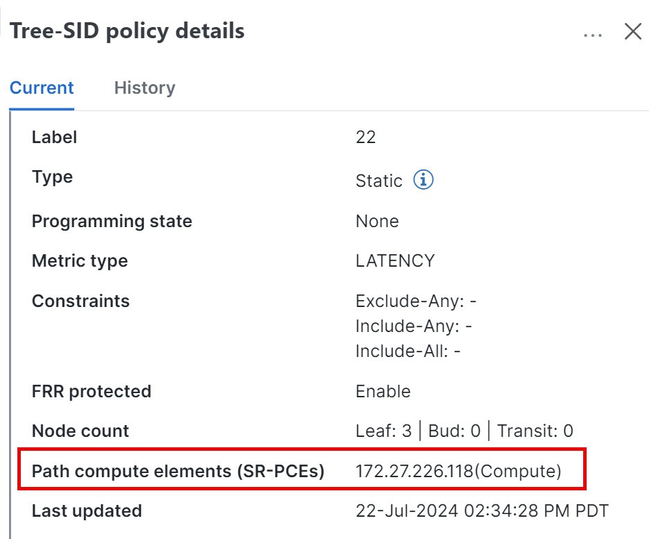
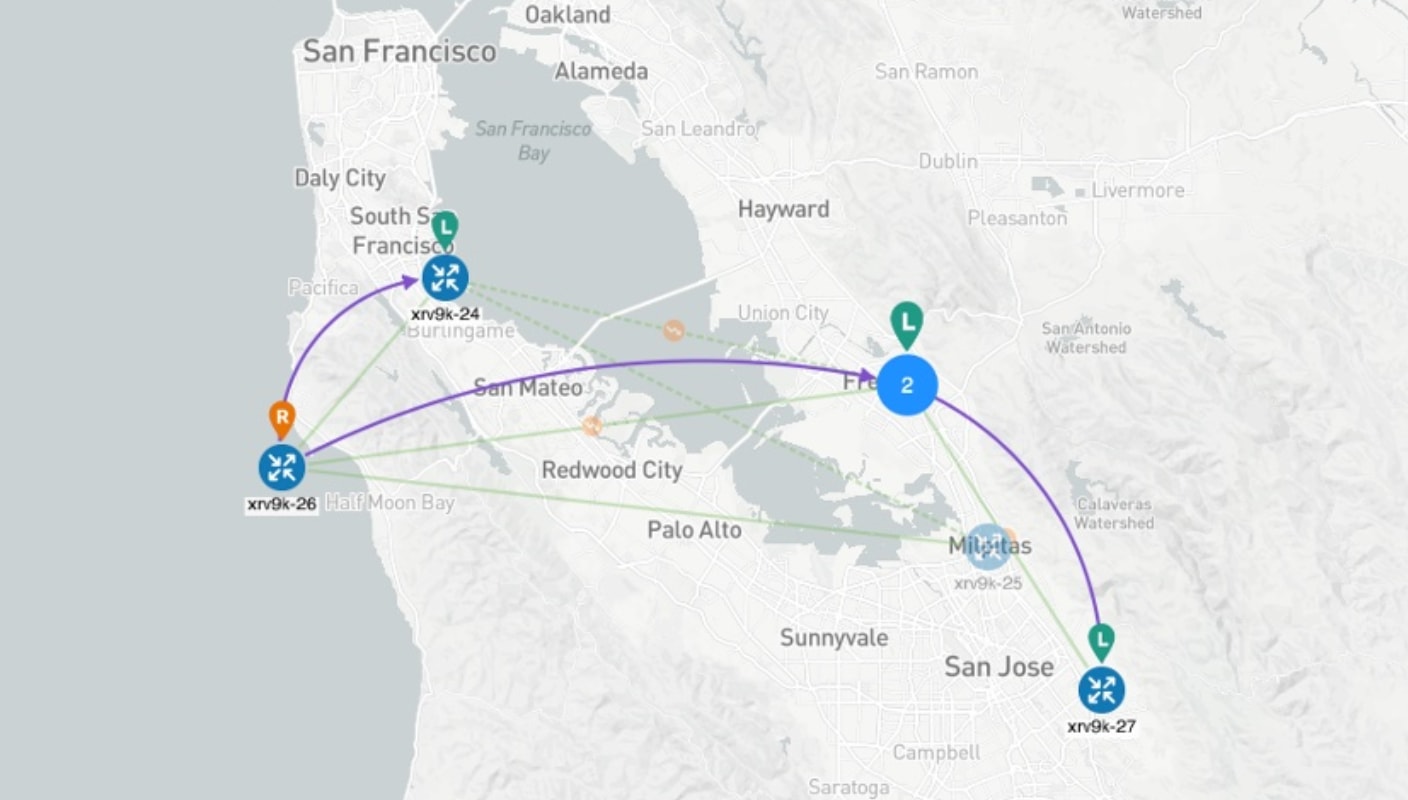
Tree-SID is a method of implementing tree-like multicast flows over a segmented routing network. Using Tree-SID, an SDN controller (a device running SR-PCE using PCEP) calculates the tree. Each node (device) in the tree has a specific role in routing the multicast data through the tree. These roles include Ingress for the root or headend node, Transit or Bud for midpoint nodes that are not leaf nodes, and Egress for destination leaf nodes. The tree itself is assigned a single SID label representing all the tree segments and devices. The SDN controller is highly flexible, as it understands the segmentation and can construct routing paths using any constraints that network architects can specify.
The most interesting use case for constraint-based Tree-SID use is where routers are configured to deliver two P2MP streams with the same content over different paths. Here, the multicast flow is forwarded twice through the network, each copy following a unique path. The two copies never use the same node or link to reach the destination, reducing packet loss due to network failures on any one of the paths.
Using Crosswork Network Controller, you can now create static tree-SID policies using the UI, associate Static mVPN tree-SID policies with a provisioned L3VPN service, and visualize, analyze, edit or delete your tree-SID policies to manage your multicast network actively.
 Note |
Static and Dynamic mVPN Tree-SID policies can be associated with an L3VPN service model. In this workflow tutorial, only a Static mVPN Tree-SID policy will be associated, visualized, and analyzed with an L3VPN service model. |
How does it work?
-
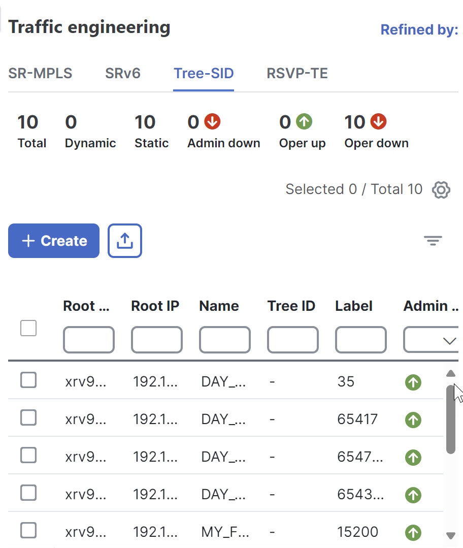
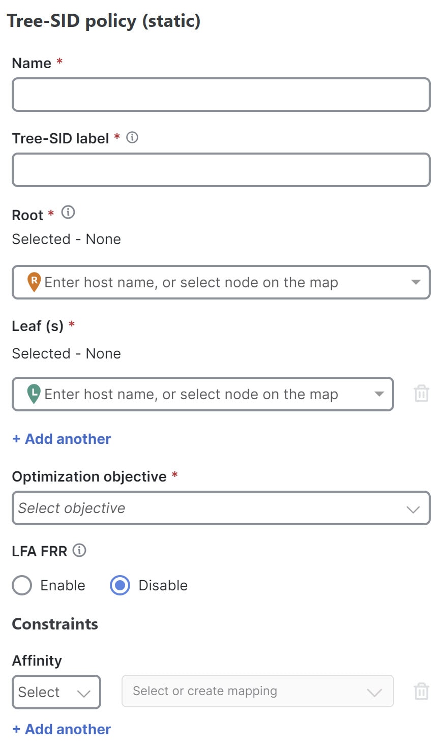
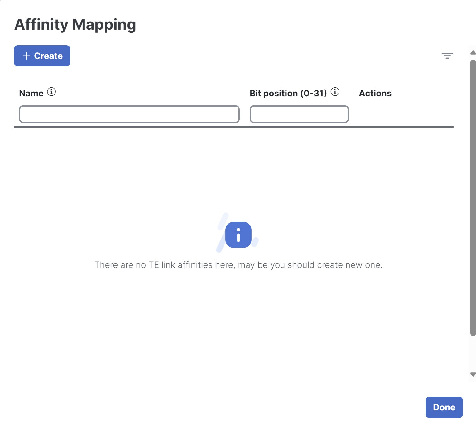
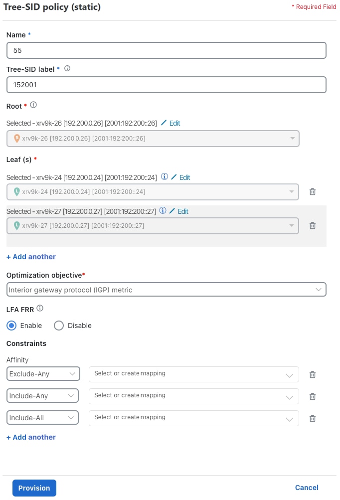
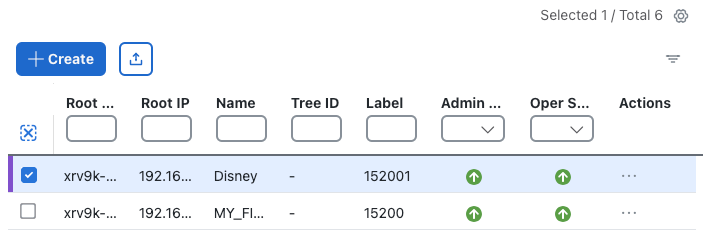
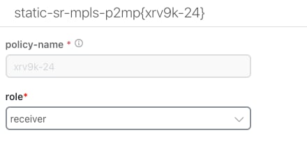
Create a static Tree-SID policy using Crosswork Network Controller UI
-
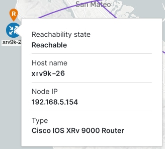
Visualize and validate the new static Tree-SID policy
-
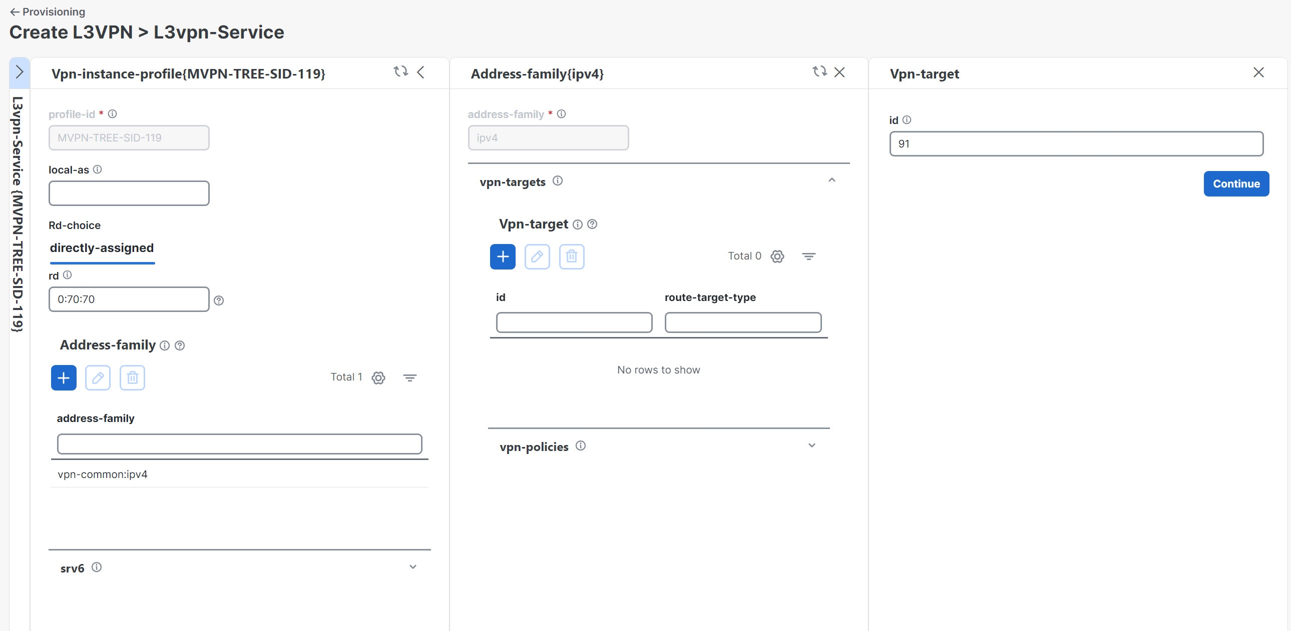
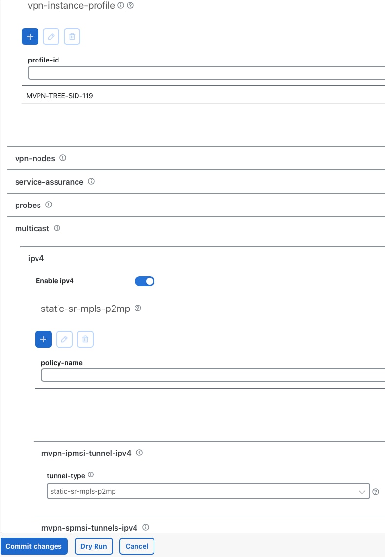
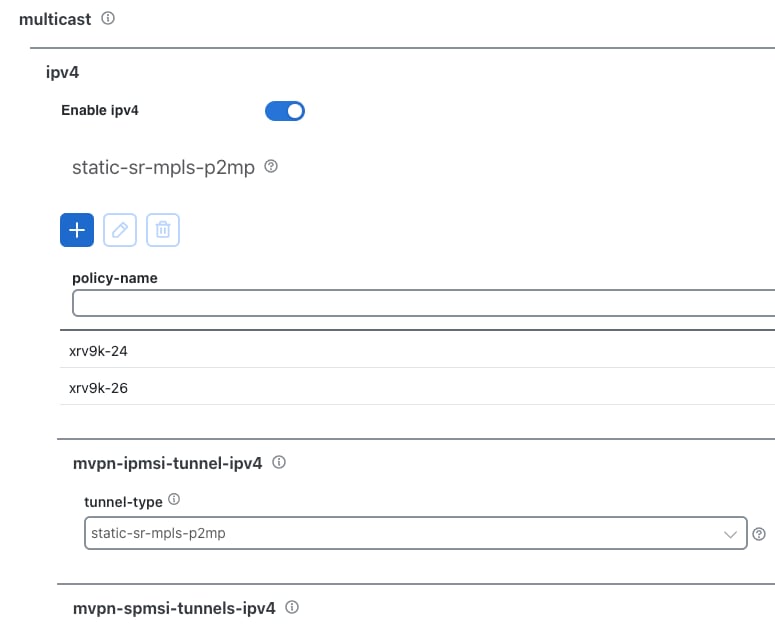
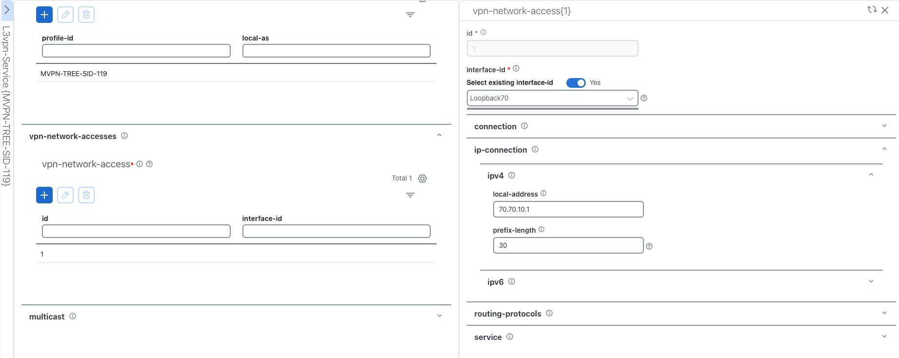
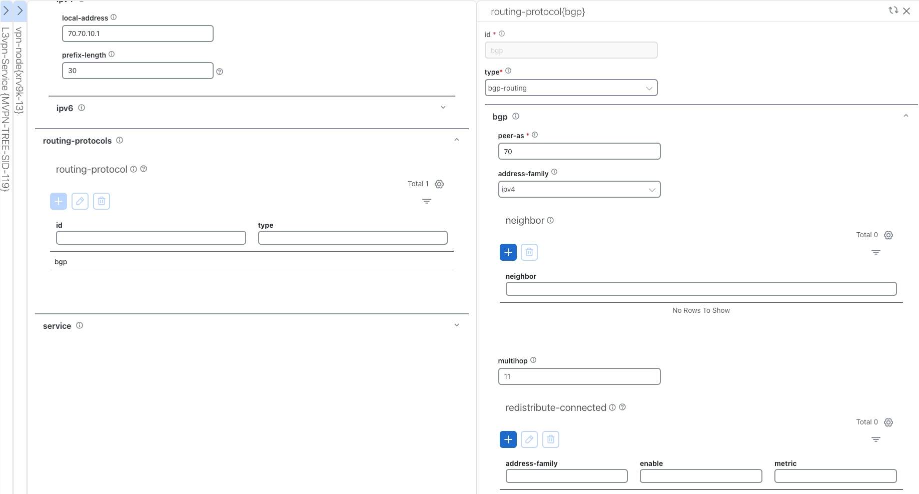
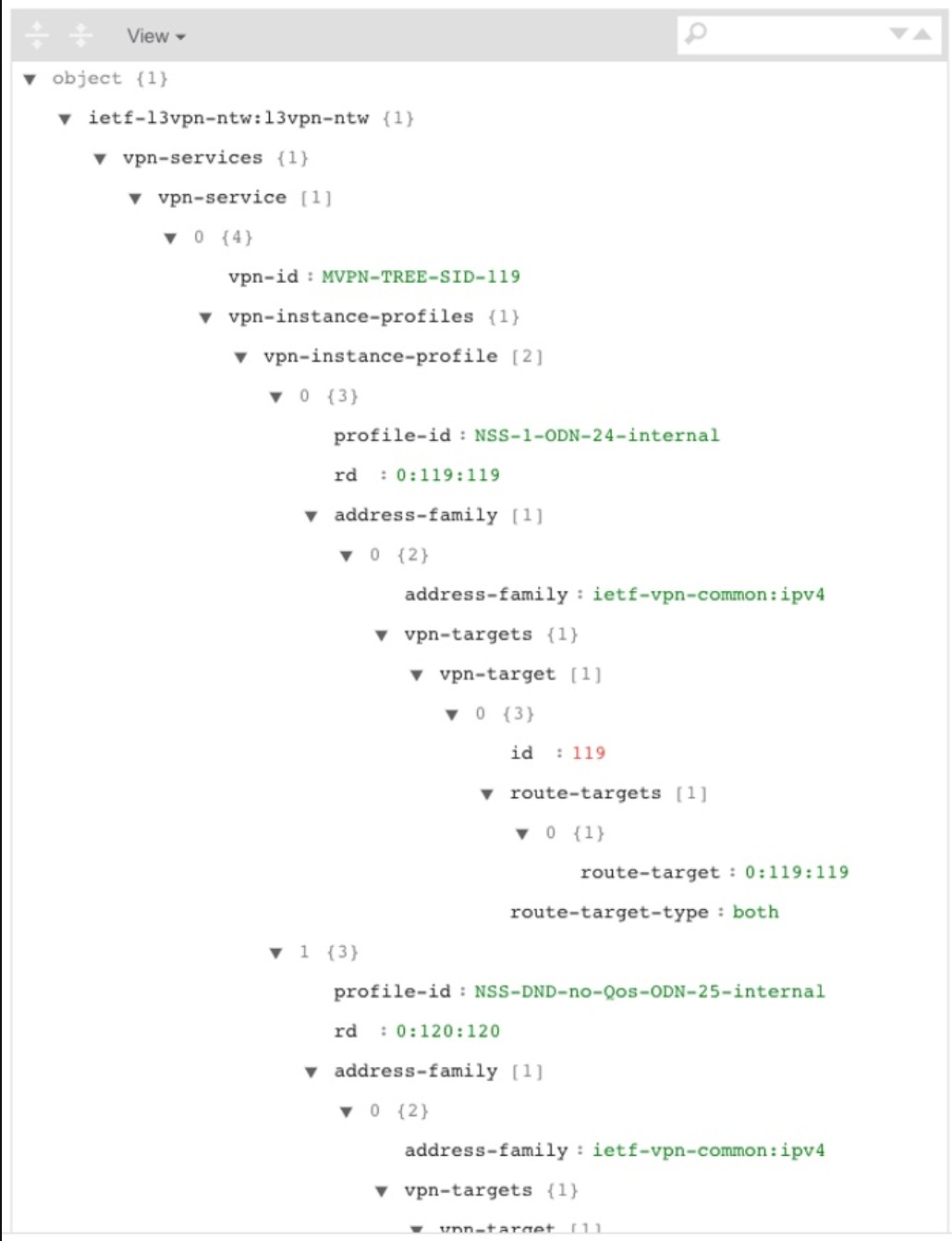
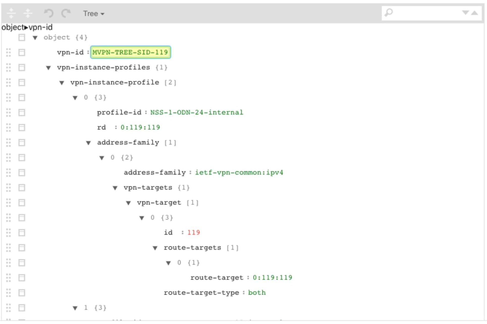
Associate your static mVPN Tree-SID policy with an L3VPN service model (or import an existing static or dynamic Tree-SID policy)
-
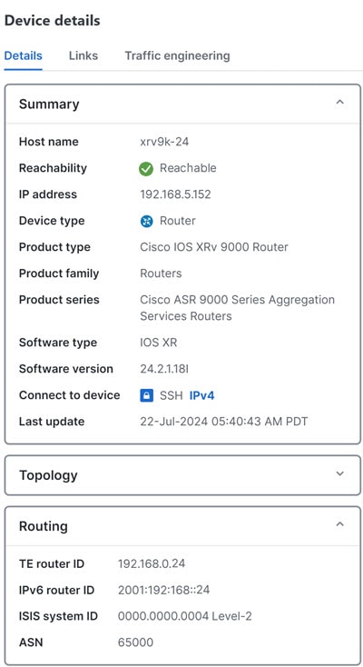
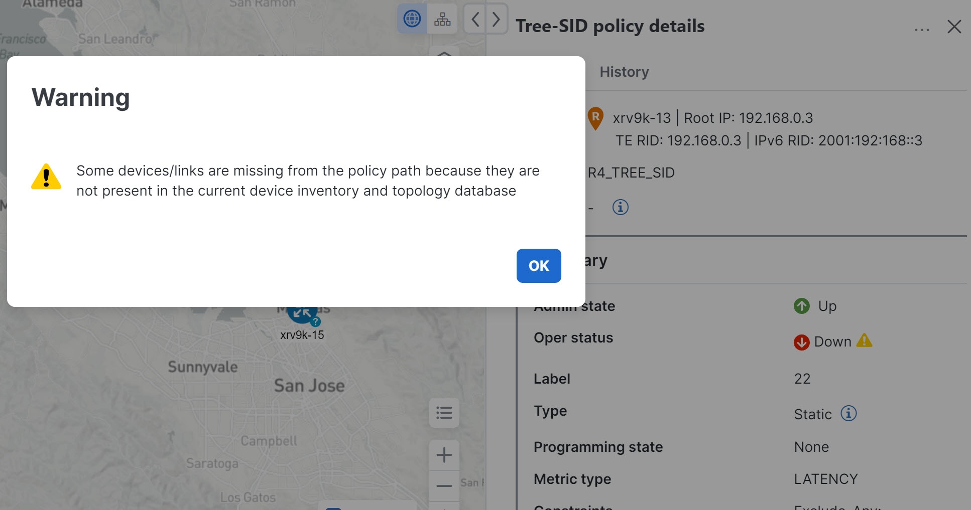
Visualize and analyze the performance details of your static mVPN Tree-SID paths and nodes within the L3VPN service model
-
Edit your existing static mVPN Tree-SID policy to enhance performance or correct issues with your Tree-SID L3VPN service model

 Feedback