-
- Downstream Interface Configuration
- Upstream Interface Configuration
- DOCSIS Interface and Fiber Node Configuration
- Service Group Based Configuration of the Cisco cBR Router
- DOCSIS Load Balancing Groups
- DOCSIS Load Balancing Movements
- DOCSIS 3.0 Downstream Bonding
- DOCSIS 2.0 A-TDMA Modulation Profiles
- Downstream Resiliency Bonding Group
- Downstream Channel ID Assignment
- Upstream Channel Bonding
- Spectrum Management and Advanced Spectrum Management
- Upstream Scheduler Mode
- Generic Routing Encapsulation
- Transparent LAN Service over Cable
- Downgrading Channel Bonding in Battery Backup Mode
- Upstream Bonding Support for D-PON
- Energy Management Mode
- Cable Modem Steering on the Cisco cBR Series Converged Broadband Routers
-
- IP Access Control Lists
- Creating an IP Access List and Applying It to an Interface
- Creating an IP Access List to Filter IP Options, TCP Flags, Noncontiguous Ports
- Refining an IP Access List
- IP Named Access Control Lists
- IPv4 ACL Chaining Support
- IPv6 ACL Chaining with a Common ACL
- Commented IP Access List Entries
- Standard IP Access List Logging
- IP Access List Entry Sequence Numbering
- ACL IP Options Selective Drop
- ACL Syslog Correlation
- IPv6 Access Control Lists
- IPv6 Template ACL
- IPv6 ACL Extensions for Hop by Hop Filtering
-
- Call Home
- SNMP Support over VPNs—Context-Based Access Control
- SNMP Cache Engine Enhancement
- Onboard Failure Logging
- Control Point Discovery
- IPDR Streaming Protocol
- Usage-Based Billing (SAMIS)
- Frequency Allocation Information for the Cisco CMTS Routers
- Flap List Troubleshooting
- Maximum CPE and Host Parameters
- SNMP Background Synchronization
- Online Offline Diagnostics
- Index
Cisco Converged Broadband Routers Software Configuration Guide For DOCSIS
Bias-Free Language
The documentation set for this product strives to use bias-free language. For the purposes of this documentation set, bias-free is defined as language that does not imply discrimination based on age, disability, gender, racial identity, ethnic identity, sexual orientation, socioeconomic status, and intersectionality. Exceptions may be present in the documentation due to language that is hardcoded in the user interfaces of the product software, language used based on RFP documentation, or language that is used by a referenced third-party product. Learn more about how Cisco is using Inclusive Language.
- Updated:
- March 28, 2016
Chapter: MPLS VPN Cable Enhancements
MPLS VPN Cable
Enhancements
This feature module describes the Multiprotocol Label Switching Virtual Private Network (MPLS VPN) and cable interface bundling features. It explains how to create a VPN using MPLS protocol, cable interfaces, bundle interfaces and sub bundle interfaces. VPNs can be created in many ways using different protocols.
- Finding Feature Information
- Hardware Compatibility Matrix for Cisco cBR Series Routers
- Feature Overview
- Prerequisites
- Configuration Tasks
- Configuration Examples
- Additional References
- Feature Information for MPLS VPN Cable Enhancements
Finding Feature Information
Finding Feature Information
Your software release may not support all the features documented in this module. For the latest feature information and caveats, see the release notes for your platform and software release. To find information about the features documented in this module, and to see a list of the releases in which each feature is supported, see the Feature Information Table at the end of this document.
Use Cisco Feature Navigator to find information about platform support and Cisco software image support. To access Cisco Feature Navigator, go to http://tools.cisco.com/ITDIT/CFN/. An account on http://www.cisco.com/ is not required.
Hardware Compatibility Matrix for Cisco cBR Series Routers
 Note | The hardware components introduced in a given Cisco IOS-XE Release are supported in all subsequent releases unless otherwise specified. |
|
Cisco CMTS Platform |
Processor Engine |
Interface Cards |
|---|---|---|
|
Cisco cBR-8 Converged Broadband Router |
Cisco IOS-XE Release 3.15.0S and Later Releases Cisco cBR-8 Supervisor:
|
Cisco IOS-XE Release 3.15.0S and Later Releases Cisco cBR-8 CCAP Line Cards: Cisco cBR-8 Downstream PHY Modules: Cisco cBR-8 Upstream PHY Modules: |
Feature Overview
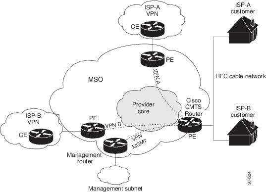
Using MPLS VPN technology, service providers can create scalable and efficient private networks using a shared hybrid fiber coaxial (HFC) network and Internet protocol (IP) infrastructure.
The cable MPLS VPN network consists of:
- The Multiple Service Operator (MSO) or cable company that owns the physical infrastructure and builds VPNs for the Internet Service Providers (ISPs) to move traffic over the cable and IP backbone.
- ISPs that use the HFC network and IP infrastructure to supply Internet service to cable customers.
Each ISP moves traffic to and from a subscriber's PC, through the MSO's physical network infrastructure, to the ISP's network. MPLS VPNs, created in Layer 3, provide privacy and security by constraining the distribution of a VPN’s routes only to the routers that belong to its network. Thus, each ISP's VPN is insulated from other ISPs that use the same MSO infrastructure.
An MPLS VPN assigns a unique VPN Routing/Forwarding (VRF) instance to each VPN. A VRF instance consists of an IP routing table, a derived forwarding table, a set of interfaces that use the forwarding table, and a set of rules and routing protocols that determine the contents of the forwarding table.
Each PE router maintains one or more VRF tables. It looks up a packet’s IP destination address in the appropriate VRF table, only if the packet arrived directly through an interface associated with that table.
MPLS VPNs use a combination of BGP and IP address resolution to ensure security. See Configuring Multiprotocol Label Switching.
The table shows a cable MPLS VPN network. The routers in the network are:
- Provider (P) router—Routers in the core of the provider network. P routers run MPLS switching, and do not attach VPN labels (MPLS label in each route assigned by the PE router) to routed packets. VPN labels are used to direct data packets to the correct egress router.
- Provider Edge (PE) router— Router that adds the VPN label to incoming packets based on the interface or subinterface on which they are received. A PE router attaches directly to a CE router. In the MPLS-VPN approach, each Cisco CMTS router acts as a PE router.
- Customer (C) router—Router in the ISP or enterprise network.
- Customer Edge (CE) router—Edge router on the ISP’s network that connects to the PE router on the MSO’s network. A CE router must interface with a PE router.
The MPLS network has a unique VPN that exclusively manages the MSOs devices called the management VPN. It contains servers and devices that other VPNs can access. The management VPN connects the Cisco CMTS router to a PE router, which connects to management servers such as Cisco Network Registrar (CNR) and Time of Day (ToD) servers. A PE router connects to management servers and is a part of the management VPN. Regardless of the ISP they belong to, the management servers serve the Dynamic Host Configuration Protocol (DHCP), DNS (Domain Name System), and TOD requests coming from PCs or cable modems.
Note | When configuring MPLS VPNs, you must configure the first subinterface created as a part of the management VPN. |
Cable VPN configuration involves an:
- MSO domain that requires a direct peering link to each enterprise network (ISP), provisioning servers for residential and commercial subscribers, and dynamic DNS for commercial users. The MSO manages cable interface IP addressing, Data-over-Cable Service Interface Specifications (DOCSIS) provisioning, CM hostnames, routing modifications, privilege levels, and usernames and passwords.
- ISP or enterprise domain that includes the DHCP server for subscriber or telecommuter host devices, enterprise gateway within the MSO address space, and static routes back to the telecommuter subnets.
Note | Cisco recommends that the MSO assign all addresses to the end user devices and gateway interfaces. The MSO can also use split management to let the ISP configure tunnels and security. |
In an MPLS VPN configuration, the MSO must configure the following:
- CMTS
- P routers
- PE routers
- CE routers
- One VPN per ISP DOCSIS servers for all cable modem customers. The MSO must attach DOCSIS servers to the management VPN, and make them visible.
The MSO must configure the Cisco CMTS routers that serve the ISP, and remote PE routers connecting to the ISP, as PE routers in the VPN.
The MSO must determine the primary IP address range for all cable modems.
The ISP must determine the secondary IP address range for subscriber PCs.
To reduce security breaches and differentiate DHCP requests from cable modems in VPNs or under specific ISP management, MSOs can use the cable helper-address command in Cisco IOS software. The MSO can specify the host IP address to be accessible only in the ISP’s VPN. This lets the ISP use its DHCP server to allocate IP addresses. Cable modem IP address must be accessible from the management VPN.
The MPLS VPN approach of creating VPNs for individual ISPs or customers requires subinterfaces to be configured on the virtual bundle interface. Each ISP requires one subinterface. The subinterfaces are tied to the VPN Routing/Forwarding (VRF) tables for their respective ISPs. The first subinterface must be created on the cable interface bound to the management VPN.
To route a reply from the CNR back to the cable modem, the PE router that connects to the CNR must import the routes of the ISP VPN into the management VPN. Similarly, to forward management requests (such as DHCP renewal to CNR) to the cable modems, the ISP VPN must export and import the appropriate management VPN routes.
You can group all of the cable interfaces on a Cisco CMTS router into a single bundle so that only one subnet is required for each router. When you group cable interfaces, no separate IP subnet or each individual cable interface is required. This grouping avoids the performance, memory, and security problems in using a bridging solution to manage subnets, especially for a large number of subscribers.
Subinterfaces allow traffic to be differentiated on a single physical interface, and assigned to multiple VPNs. You can configure multiple subinterfaces, and associate an MPLS VPN with each subinterface. You can split a single physical interface (the cable plant) into multiple subinterfaces, where each subinterface is associated with a specific VPN. Each ISP requires access on a physical interface and is given its own subinterface. Create a management subinterface to support cable modem initialization from an ISP.
Using each subinterface associated with a specific VPN (and therefore, ISP) subscribers connect to a logical subinterface, which reflects the ISP that provides their subscribed services. When properly configured, subscriber traffic enters the appropriate subinterface and VPN.
Benefits
- MPLS VPNs give cable MSOs and ISPs a manageable way of supporting multiple access to a cable plant. Service providers can create scalable and efficient VPNs across the core of their networks. MPLS VPNs provide systems support scalability in cable transport infrastructure and management.
- Each ISP can support Internet access services from a subscriber’s PC through an MSO’s physical cable plant to their networks.
- MPLS VPNs allow MSOs to deliver value-added services through an ISP, and thus, deliver connectivity to a wider set of potential customers. MSOs can partner with ISPs to deliver multiple services from multiple ISPs and add value within the MSO’s own network using VPN technology.
- Subscribers can select combinations of services from various service providers.
- The MPLS VPN cable features set build on CMTS DOCSIS 1.0 and DOCSIS 1.0 extensions to ensure services are reliably and optimally delivered over the cable plant. MPLS VPN provides systems support domain selection, authentication per subscriber, selection of QoS, policy-based routing, and ability to reach behind the cable modem to subscriber end devices for QoS and billing while preventing session spoofing.
- MPLS VPN technology ensures both secure access across the shared cable infrastructure and service integrity.
- Cable interface bundling eliminates the need for an IP subnet on each cable interface. Instead, an IP subnet is only required for each cable interface bundle. All cable interfaces in a Cisco CMTS router can be added to a single bundle.
Restrictions
- Each subinterface on the CMTS requires an address range from the ISP and from the MSO. These two ranges must not overlap and must be extensible to support an increased number of subscribers for scalability.
Note | This document does not address allocation and management of MSO and ISP IP addresses. See Configuring Multiprotocol Label Switching for this information. |
- The cable source-verify dhcp command enables Dynamic Host Control Protocol (DHCP) Lease query protocol from the CMTS to DHCP server to verify IP addresses of upstream traffic, and prevent MSO customers from using unauthorized, spoofed, or stolen IP addresses.
- When using only MPLS VPNs, create subinterfaces on the virtual bundle, assign it an IP address, and provide VRF configuration for each ISP. When you create subinterfaces and configure only MPLS VPNs, the cable interface bundling feature is independent of the MPLS VPN.
- When using cable
interface bundling:
- Define a virtual bundle interface and associate any cable physical interface to the virtual bundle.
- Specify all generic IP networking information (such as IP address, routing protocols, and switching modes) on the virtual bundle interface. Do not specify generic IP networking information on bundle slave interfaces.
- An interface that has a subinterface(s) defined over it is not allowed to be a part of the bundle.
- Specify generic (not downstream or upstream related) cable interface configurations, such as source-verify or ARP handling, on the virtual bundle interface. Do not specify generic configuration on bundle slave interfaces.
- Interface bundles can only be configured using the command line interface (including the CLI-based HTML configuration).
Prerequisites
Before configuring IP-based VPNs, complete the following tasks:
- Ensure your network supports reliable broadband data transmission. Your plant must be swept, balanced, and certified based on National Television Standards Committee (NTSC) or appropriate international cable plant recommendations. Ensure your plant meets all DOCSIS or European Data-over-Cable Service Interface Specifications (EuroDOCSIS) downstream and upstream RF requirements.
- Ensure your Cisco router is installed following instructions in the Hardware Installation Guide and the Regulatory Compliance and Safety Information guide.
- Ensure your Cisco router is configured for basic operations.
- The chassis must contain at least one port adapter to provide backbone connectivity and one Cisco cable modem card to serve as the RF cable TV interface.
Other Important Information
- Ensure all other required headend or distribution hub routing and network interface equipment is installed, configured, and operational based on the services to support. This includes all routers, servers (DHCP, TFTP, and ToD), network management systems, other configuration or billing systems and backbone, and other equipment to support VPN.
- Ensure DHCP and DOCSIS configuration files have been created and pushed to appropriate servers such that each cable modem, when initialized, can transmit a DHCP request, receive an IP address, obtain TFTP and ToD server addresses, and download a DOCSIS configuration file. Configure each subinterface to connect to the ISP’s VPN.
- Ensure DOCSIS servers are visible on the management VPN.
- Be familiar with your channel plan to assign appropriate frequencies. Outline your strategies for setting up bundling or VPN solution sets if applicable to your headend or distribution hub. Obtain passwords, IP addresses, subnet masks, and device names as appropriate.
- Create subinterfaces off of a virtual bundle interface. Configure each subinterface to connect to the ISP network.
The MPLS VPN configuration steps assume the following:
- IP addressing has already been determined and there are assigned ranges in the MSO and ISP network for specific subinterfaces.
- The MSO is using CNR and has configured it (using the cable helper-address command) to serve appropriate IP addresses to cable modems based on the cable modem MAC address. The CMTS forwards DHCP requests to the CNR based on the cable helper-address settings. The CNR server determines the IP address to assign the cable modem using the client-classes feature, which let the CNR assign specific parameters to devices based on MAC addresses.
- ISP CE routers are configured (using the cable helper-address command) to appropriately route relevant IP address ranges into the VPN.
- P and PE routers are already running Cisco Express Forwarding (CEF).
- MPLS is configured on the outbound VPN using the tag switching ip command in interface configuration mode.
Configuration Tasks
To configure MPLS VPNs, perform the following tasks:
- Creating VRFs for each VPN
- Defining Subinterfaces on a Virtual Bundle Interface and Assigning VRFs
- Configuring Cable Interface Bundles
- Configuring Subinterfaces and MPLS VPNs on a Virtual Bundle Interface
- Configuring MPLS in the P Routers in the Provider Core
- Verifying the MPLS VPN Configuration
Creating VRFs for each VPN
To create VRFs for each VPN, perform the following steps beginning in the router configuration mode.
Note | Since only the CMTS has logical subinterfaces, assignments of VRFs on the other PE devices will be to specific physical interfaces. |
Defining Subinterfaces on a Virtual Bundle Interface and Assigning VRFs
To create a logical cable subinterface, perform the following steps beginning in the global configuration mode. Create one subinterface for each VPN (one per ISP). The first subinterface created must be configured as part of the management VPN (with the lowest subinterface number).
Configuring Cable Interface Bundles
To assign a cable interface to a bundle, perform the following steps beginning in the interface configuration mode.
Configuring Subinterfaces and MPLS VPNs on a Virtual Bundle Interface
To configure subinterfaces on a virtual bundle interface and assign each subinterface a Layer 3 configuration:
Configure cable interface bundles.
Define subinterfaces on the virtual bundle interface and assign a Layer 3 configuration to each subinterface.
Create one subinterface for each customer VPN (one per ISP).
Configuring MPLS in the P Routers in the Provider Core
To configure MPLS in the P routers in the provider core, perform the following steps.
Verifying the MPLS VPN Configuration
Use the following commands to verify MPLS VPN operations on PE routers. For more MPLS VPN verification commands, see Configuring Multiprotocol Label Switching.
For more verification instructions, see the MPLS: Layer 3 VPNs Configuration Guide.
Configuration Examples
This section provides the following configuration examples:
- VRF Definition Configuration
- Cable Bundle SubInterface Configuration
- PE WAN Interface Configuration
- PE BGP Configuration
VRF Definition Configuration
vrf definition Basketball
 rd 100:2
 route-target export 100:2
 route-target import 100:0
 route-target import 100:2
 !
 address-family ipv4
 exit-address-family
 !
 address-family ipv6
 exit-address-family
vrf definition Football
 rd 100:1
 route-target export 100:1
 route-target import 100:0
 route-target import 100:1
 !
 address-family ipv4
 exit-address-family
 !
 address-family ipv6
 exit-address-family
vrf definition MGMT
 rd 100:0
 route-target export 100:0
 route-target import 100:0
 !
 address-family ipv4
 exit-address-family
 !
 address-family ipv6
 exit-address-family
vrf definition Mgmt-intf
 !
 address-family ipv4
 exit-address-family
 !
 address-family ipv6
 exit-address-family
vrf definition Tennis
 rd 100:4
 route-target export 100:4
 route-target import 100:0
 route-target import 100:4
 !
 address-family ipv4
 exit-address-family
 !
 address-family ipv6
 exit-address-family
vrf definition Volleyball
 rd 100:3
 route-target export 100:3
 route-target import 100:0
 route-target import 100:3
 !
 address-family ipv4
 exit-address-family
 !
 address-family ipv6
 exit-address-family
Cable Bundle SubInterface Configuration
interface Bundle255
 description Bundle Master Interface
 no ip address
 cable arp filter request-send 3 2
 cable arp filter reply-accept 3 2

interface Bundle255.1
 description Management Interface
 vrf forwarding MGMT
 ip address 112.51.0.1 255.255.0.0
 cable helper-address 20.11.0.162
 ipv6 address 2001:100:112:B001::1/64

interface Bundle255.2
 vrf forwarding Basketball
 ip address 112.54.0.1 255.255.0.0 secondary
 ip address 112.53.0.1 255.255.0.0
 cable helper-address 20.11.0.62
 cable helper-address 20.11.0.162
 ipv6 address 2001:100:112:B003::1/64
 ipv6 address 2001:100:112:B004::1/64

interface Bundle255.3
 vrf forwarding Football
 ip address 112.56.0.1 255.255.0.0 secondary
 ip address 112.55.0.1 255.255.0.0
 cable helper-address 20.11.0.62
 cable helper-address 20.11.0.162
 ipv6 address 2001:100:112:B005::1/64
 ipv6 address 2001:100:112:B006::1/64

interface Bundle255.4
 vrf forwarding Volleyball
 ip address 112.58.0.1 255.255.0.0 secondary
 ip address 112.57.0.1 255.255.0.0
 cable helper-address 20.11.0.62
 cable helper-address 20.11.0.162
 ipv6 address 2001:100:112:B007::1/64
 ipv6 address 2001:100:112:B008::1/64

interface Bundle255.5
 vrf forwarding Tennis
 ip address 112.61.0.1 255.255.0.0 secondary
 ip address 112.60.0.1 255.255.0.0 secondary
 ip address 112.59.0.1 255.255.0.0
 cable helper-address 20.11.0.162
 ipv6 address 2001:100:112:B009::1/64
 ipv6 address 2001:100:112:B00A::1/64
PE WAN Interface Configuration
mpls label protocol ldp
mpls ldp nsr
mpls ldp graceful-restart

interface TenGigabitEthernet4/1/1
 description WAN connection to cBR8
 mtu 4470
 ip address 100.6.120.5 255.255.255.252
 ip router isis hub
 ipv6 address 2001:100:6:120::5:1/112
 ipv6 enable
 mpls ip
 mpls traffic-eng tunnels
 cdp enable
 isis circuit-type level-1
 isis network point-to-point
 isis csnp-interval 10
 hold-queue 400 in
 ip rsvp bandwidth 1000000
end
PE BGP Configuration
router bgp 100
 bgp router-id 100.120.120.120
 bgp log-neighbor-changes
 bgp graceful-restart restart-time 120
 bgp graceful-restart stalepath-time 360
 bgp graceful-restart
 timers bgp 5 60
 neighbor 100.100.4.4 remote-as 100
 neighbor 100.100.4.4 ha-mode sso
 neighbor 100.100.4.4 update-source Loopback0
 neighbor 100.100.4.4 ha-mode graceful-restart
 !
 address-family ipv4
  redistribute connected
  redistribute static route-map static-route
  redistribute rip
  neighbor 100.100.4.4 activate
  neighbor 100.100.4.4 send-community extended
  neighbor 100.100.4.4 next-hop-self
  neighbor 100.100.4.4 soft-reconfiguration inbound
  maximum-paths ibgp 2
 exit-address-family
 !
 address-family vpnv4
  neighbor 100.100.4.4 activate
  neighbor 100.100.4.4 send-community extended
 exit-address-family
 !
 address-family ipv6
  redistribute connected
  redistribute rip CST include-connected
  redistribute static metric 100 route-map static-route-v6
  neighbor 100.100.4.4 activate
  neighbor 100.100.4.4 send-community extended
  neighbor 100.100.4.4 send-label
 exit-address-family
 !
 address-family vpnv6
  neighbor 100.100.4.4 activate
  neighbor 100.100.4.4 send-community extended
 exit-address-family
 !
 address-family ipv4 vrf Basketball
  redistribute connected
 exit-address-family
 !
 address-family ipv6 vrf Basketball
  redistribute connected
  redistribute static metric 100
 exit-address-family
 !
 address-family ipv4 vrf Football
  redistribute connected
 exit-address-family
 !
 address-family ipv6 vrf Football
  redistribute connected
  redistribute static metric 100
 exit-address-family
 !
 address-family ipv4 vrf MGMT
  redistribute connected
 exit-address-family
 !
 address-family ipv6 vrf MGMT
  redistribute connected
 exit-address-family
 !
 address-family ipv4 vrf Tennis
  redistribute connected
  redistribute static route-map static-route
  redistribute rip
 exit-address-family
 !
 address-family ipv6 vrf Tennis
  redistribute connected
  redistribute rip CST include-connected
  redistribute static metric 100 route-map static-route-v6
 exit-address-family
 !
 address-family ipv4 vrf Volleyball
  redistribute connected
  redistribute static route-map static-route
  redistribute rip
 exit-address-family
 !
 address-family ipv6 vrf Volleyball
  redistribute connected
  redistribute rip CST include-connected
  redistribute static metric 100 route-map static-route-v6
 exit-address-family
Additional References
Standards
|
Standard |
Title |
|---|---|
|
DOCSIS 1.0 |
DOCSIS 1.0 |
MIBs
|
MIB |
MIBs Link |
|---|---|
|
CISCO-DOCS-REMOTE-QUERY.my |
To locate and download MIBs for selected platforms, Cisco IOS releases, and feature sets, use Cisco MIB Locator found at the following URL: |
RFCs
|
RFC |
Title |
|---|---|
|
RFC 1163 |
A Border Gateway Protocol |
|
RFC 1164 |
Application of the Border Gateway Protocol in the Internet |
|
RFC 2283 |
Multiprotocol Extensions for BGP-4 |
|
RFC 2547 |
BGP/MPLS VPNs |
|
RFC 2233 |
DOCSIS OSSI Objects Support |
|
RFC 2669 |
Cable Device MIB |
Technical Assistance
|
Description |
Link |
|---|---|
|
The Cisco Support and Documentation website provides online resources to download documentation, software, and tools. Use these resources to install and configure the software and to troubleshoot and resolve technical issues with Cisco products and technologies. Access to most tools on the Cisco Support and Documentation website requires a Cisco.com user ID and password. |
Feature Information for MPLS VPN Cable Enhancements
Use Cisco Feature Navigator to find information about platform support and software image support. Cisco Feature Navigator enables you to determine which software images support a specific software release, feature set, or platform. To access Cisco Feature Navigator, go to http://tools.cisco.com/ITDIT/CFN/. An account on http://www.cisco.com/ is not required.
Note | The below table lists only the software release that introduced support for a given feature in a given software release train. Unless noted otherwise, subsequent releases of that software release train also support that feature. |
|
Feature Name |
Releases |
Feature Information |
|---|---|---|
|
Multiprotocol Label Switching Virtual Private Network (MPLS VPN) |
IOS-XE 3.15.0S |
This feature was introduced on the Cisco cBR Series Routers. |
 Feedback