The switch has two alarm input and one alarm output relay circuits for external alarms. The alarm input circuits are designed
to sense if an external dry contact is open or closed relative to the alarm input reference pin. Each alarm input can be configured
as an open or closed contact. The alarm output relay circuit has a normally open and a normally closed contact.
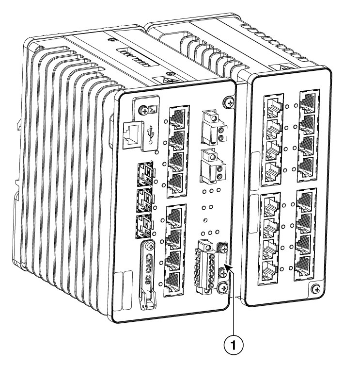
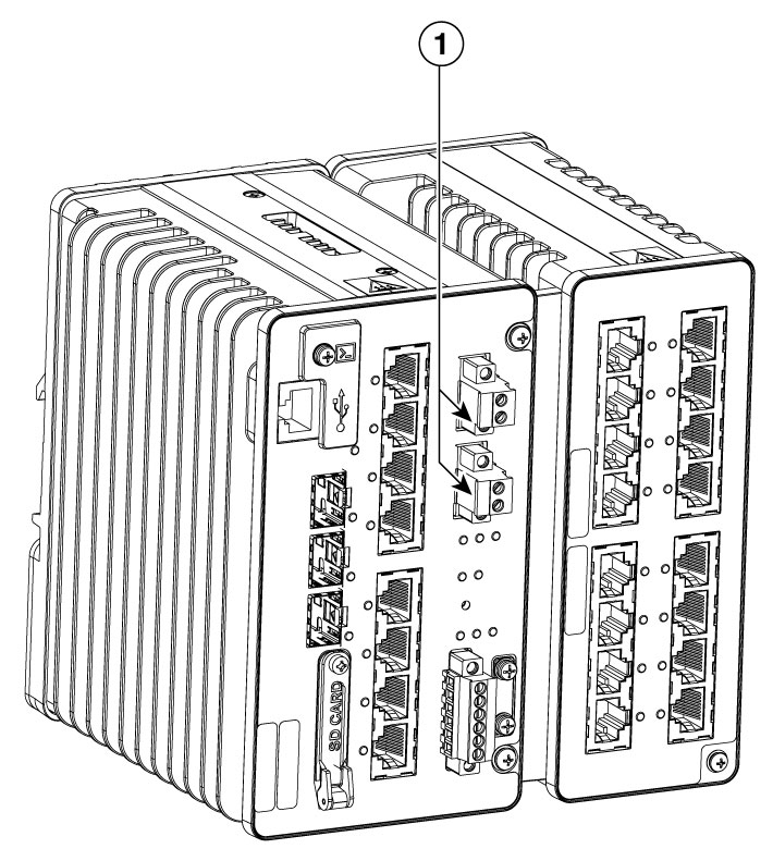
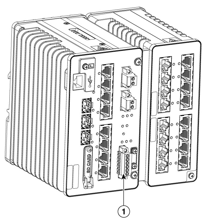
Alarm signals are connected to the switch through the six-pin alarm connector. Three connections are dedicated to the two
alarm input circuits: alarm input 1, alarm input 2, and and alarm input reference. An alarm input and the reference wiring
connection are required to complete a single alarm input circuit. The three remaining connections are for the alarm output
circuit: a normally open output, a normally closed output, and a common signal. An alarm output and the common wiring connection
are required to complete a single alarm output circuit.
The labels for the alarm connector are on the switch panel and are displayed below.
|
Label
|
Connection
|
|
NO
|
Alarm Output Normally Open (NO) connection
|
|
COM
|
Alarm Output Common connection
|
|
NC
|
Alarm Output Normally Closed (NC) connection
|
|
IN2
|
Alarm Input 2
|
|
REF
|
Alarm Input Reference Ground connection
|
|
IN1
|
Alarm Input 1
|

Caution
|
The voltage applied to the alarm output relay circuit must be an isolated source and limited to less than or equal to 24 VDC,
1.0 A or 48 VDC, 0.5 A.
|
Caution
|
To reduce risk of electric shock and fire, the alarm output relay must be connected to an IEC60950/IEC 62368 compliant limited
power source.
|

Note
|
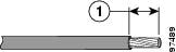
Wire connections to the power and alarm connectors must use copper wire that is appropriately-rated for the installation environment.
|
To wire the switch to an external alarm device, follow these steps:


 Feedback