Cable and Connectors
Connector Specifications
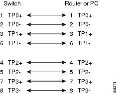
10/100/1G Ports
The 10/100/1G Ethernet ports on the switches use RJ-45 connectors.
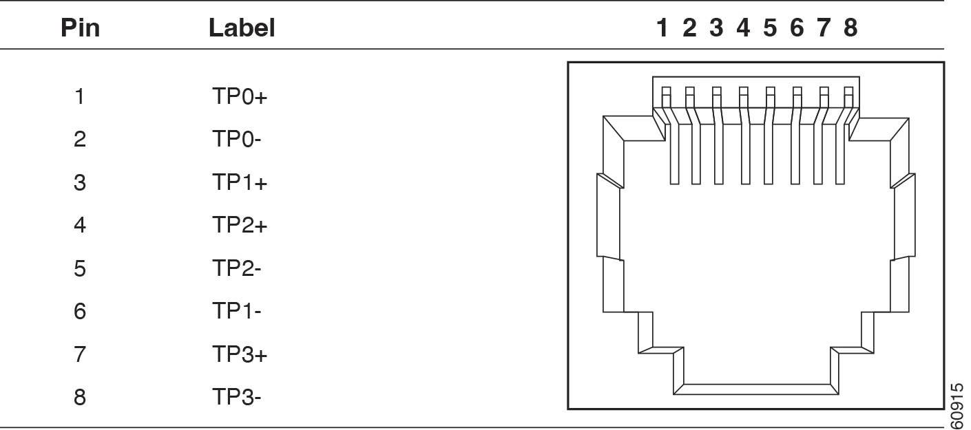
 Note |
Connector pins 1, 2, 3, and 6 are used for PoE. |
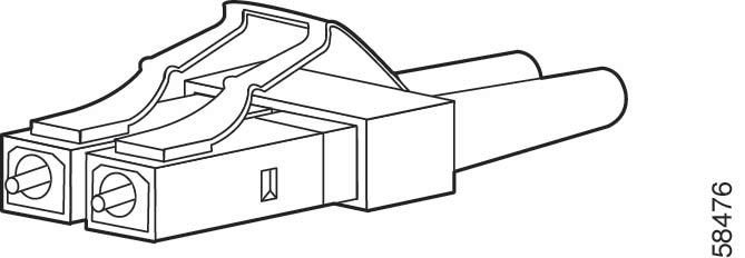
SFP Module Connectors
The illustration below shows an LC style connector that is used with the SFP Module slots. It is a fiber-optic cable connector.
 Warning |
Statement 1051—Laser Radiation Invisible laser radiation may be emitted from disconnected fibers or connectors. Do not stare into beams or view directly with optical instruments. |
Console Port
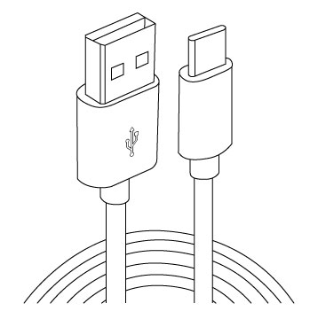
The switch has two console ports: a USB-C port on the front panel (see image below) and an RJ-45 console port on the rear panel.
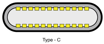
The USB console port uses a USB-C cable, shown in the illustration. The USB-C cable is not supplied.
The RJ-45 console port uses an 8-pin RJ-45 connector. A RJ45-to-DB-9 adapter cable is used to connect the console port of the switch to a console PC.
Alarm Port
The labels for the alarm connector pin-outs are on the switch panel and are displayed below.
|
Label |
Connection |
|---|---|
|
NO |
Alarm Output Normally Open (NO) connection |
|
COM |
Alarm Output Common connection |
|
NC |
Alarm Output Normally Closed (NC) connection |
|
IN2 |
Alarm Input 2 |
|
REF |
Alarm Input Reference Ground connection |
|
IN1 |
Alarm Input 1 |
Cables and Adapters
SFP Module Cables
Each port must match the wave-length specifications on each end of the cable, and for reliable communications, the cable must not exceed the allowable length. Refer to the Data Sheets for the complete list of supported SFP Modules and cables.
Note |
|
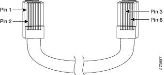
Cable Pinouts
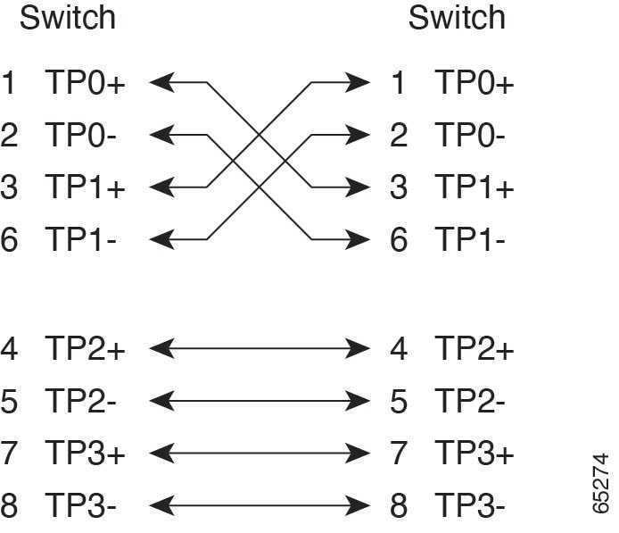
To identify a crossover cable, hold the cable ends side-by-side, with the tab at the back. The wire connected to pin 1 on the left end should be the same color as the wire connected to pin 3 on the right end. The wire connected to pin 2 on the left end should be the same color as the wire connected to pin 6 on the right end.
Console Port Adapter Pinouts
The console port uses an 8-pin RJ-45 connector. If you did not order a console cable, you need to provide an RJ-45-to-DB-9 adapter cable to connect the switch console port to a PC console port. You need to provide an RJ-45-to-DB-25 female DTE adapter if you want to connect the switch console port to a terminal.
|
Switch ConsolePort (DTE) |
RJ-45-to-DB-9Terminal Adapter |
ConsoleDevice |
|---|---|---|
|
Signal |
DB-9 Pin |
Signal |
|
RTS |
8 |
CTS |
|
DTR |
6 |
DSR |
|
TxD |
2 |
RxD |
|
GND |
5 |
GND |
|
RxD |
3 |
TxD |
|
DSR |
4 |
DTR |
|
CTS |
7 |
RTS |
Note |
The RJ-45-to-DB-25 female DTE adapter is not supplied with the switch. |
|
SwitchConsolePort (DTE) |
RJ-45-to-DB-25Adapter |
ConsoleDevice |
|---|---|---|
|
Signal |
DB-25 Pin |
Signal |
|
RTS |
5 |
CTS |
|
DTR |
6 |
DSR |
|
TxD |
3 |
RxD |
|
GND |
7 |
GND |
|
RxD |
2 |
TxD |
|
DSR |
20 |
DTR |
|
CTS |
4 |
RTS |
 Feedback