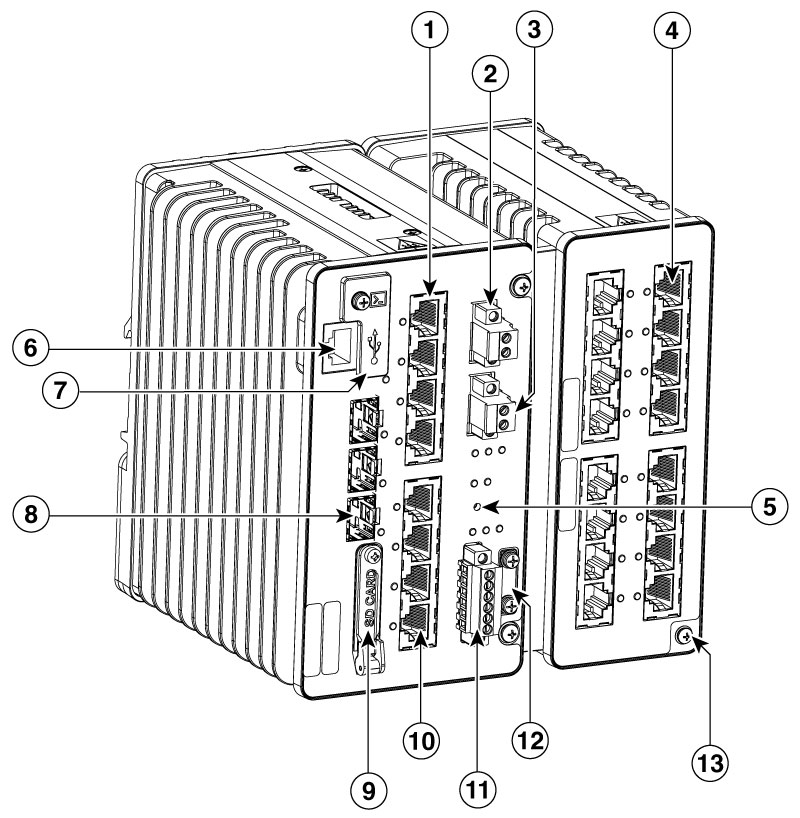
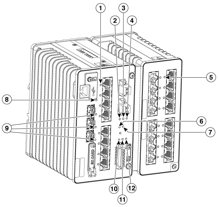
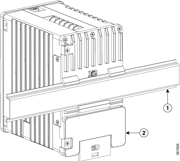
Cisco IE3500, IE3505 Rugged Series Switches

Product Overview

Cisco IE3500, IE3505 Rugged Series Switches are ruggedized Ethernet switching platforms that provide superior high-bandwidth, secure switching and industry-leading redundancy features for industrial environments, all built on the proven Cisco IOS XE Software.

These DIN-rail Industrial Ethernet switches are designed for deployments requiring hardened products, such as factory automation, smart cities, energy and process control, intelligent transportation systems (ITS), energy production sites, smart city programs, and mining. They offer high performance, high bandwidth, a rich feature set, rugged hardware, and class-leading security features. Built to withstand extreme environments, they adhere to IT network design, compliance, and performance requirements.

Security features include:

  • Cisco Trusted Platform Module (TPM)—serves as a hardware root-of-trust.

  • Secure Boot—uses a public key to validate each subsequent booting stage.

  • Chip guard—Security feature that records unique ID of critical system components to detect hardware tampering.

Switch Models

License Level

Description

IE-3500-8T3S-E

Network Essentials

8x Ethernet 10/100/1000 RJ45 ports, 3x fiber 100/1000 SFP ports, non-PoE

IE-3500-8P3S-E

Network Essentials

8x Ethernet 10/100/1000 PoE/PoE+ ports, 3x fiber 100/1000 SFP ports;

PoE power budget of 360 W (including expansion module)

IE-3505-8T3S-E

Network Essentials

8x Ethernet 10/100/1000 RJ45 ports, 3x fiber 100/1000 SFP ports, non-PoE

IE-3505-8P3S-E

Network Essentials

8x Ethernet 10/100/1000 PoE/PoE+ ports, 3x fiber 100/1000 SFP ports

PoE power budget of 480 W (including expansion module)

IE-3500-8T3X-E

Network Essentials

8x Ethernet 10/100/1000 ports, 3x 1G/10G fiber SFP+ ports, non-PoE

IE-3500-8U3X-E

Network Essentials

8x Ethernet 10/100/1000 4PPoE ports, 3x 1G/10G fiber SFP+ ports

PoE power budget of 480 W (including expansion module)

IE-3500-8T3S-A

Network Advantage

8x Ethernet 10/100/1000 RJ45 ports, 3x fiber 100/1000 SFP ports, non-PoE

IE-3500-8P3S-A

Network Advantage

8x Ethernet 10/100/1000 PoE/PoE+ ports, 3x fiber 100/1000 SFP ports

PoE power budget of 360 W (including expansion module)

IE-3505-8T3S-A

Network Advantage

8x Ethernet 10/100/1000 RJ45 ports, 3x fiber 100/1000 SFP ports, non-PoE

IE-3505-8P3S-A

Network Advantage

8x Ethernet 10/100/1000 PoE/PoE+ ports, 3x fiber 100/1000 SFP ports

PoE power budget of 480 W (including expansion module)

IE-3500-8T3X-A

Network Advantage

8x Ethernet 10/100/1000 ports, 3x 1G/10G fiber SFP+ ports, non-PoE

IE-3500-8U3X-A

Network Advantage

8x Ethernet 10/100/1000 4PPoE ports, 3x 1G/10G fiber SFP+ ports

PoE power budget of 480 W (including expansion module)


Note


The primary switch's power ratings account for the power supplied to the supported expansion modules. Since the expansion modules cannot function as standalone devices, they do not have independent power ratings. The installer must configure the PoE power budget to match the installed power supply(s).


Front Panel

The illustration below provides an overview of an Cisco IE3500-family switch. Not all models are illustrated.

Figure 1. Cisco IE3500/IE3505 switch with expansion module

1

10/100/1G Copper Ethernet ports (downlink ports)

8

SFP module slots (uplink ports)

2

Power connector DC-A

9

Flash memory card slot

3

Power connector DC-B

10

10/100/1G Copper Ethernet ports (downlink ports)

4

Expansion Module (Port types vary)

11

Alarm connector

5

Express Setup Button (recessed)

12

Protective ground connection

6

RJ-45 console port

13

EMC Ground

7

USB C Console Port and USB A host port (behind cover) 1

1 Use a Phillips screwdriver to remove the port cover and access the port.

Note


The USB ports are intended only for service operation and not for continuous use.

Ports

Note: Different configurations are available. Not all ports or slots are present in all configurations.

Console Ports

You can connect the switch to a computer or to a terminal server through either the RJ-45 console port or the USB-C console port.

The switch includes two console ports for management and configuration.

  • RS-232 Console Port: Features an RJ-45 connector and supports connections to a terminal server or an RS-232 port

  • USB-C Console Port: For use with a computer running a terminal emulator application

    The USB-C console port is a standard Communication Device Class (CDC) device. It is compatible with the CDC driver included in most operating systems. This port functions exclusively as a USB device and does not operate as a host port. It cannot be used to power the switch

The USB-C console and RJ-45 console operate at the same configured baud rate interface speeds.

Power Connectors

DC Power Connector

Connect DC power to the switch through the front panel connectors. The switch has two DC power input connectors (DC-A and DC-B). Each power connector has an LED status indicator.

The switch power connectors are attached to the switch chassis. Each power connector has screw terminals for terminating the DC power. All connectors are secured to the switch front panel with the provided captive screws.

The switch can operate with a single power source or with dual power sources. When both power sources are operational, the switch draws power from the DC source with the higher voltage. If one of the two power sources fail, the other continues to power the switch.

When using two power supplies that support PoE, set the system PoE Power Budget to match the smaller capacity supply.

Cisco provides a range of DIN-rail DC power supplies suitable for many applications. Installers may also use third-party power supplies, provided they meet the switch's specifications.

Cisco will support the switch when powered by a third-party power supply, however, it does not provide support for the third-party power supply itself. Customers with questions about installing or troubleshooting a third-party power supply should contact the power supply vendor directly.

Alarm Connector

You connect the alarm signals to the switch through the alarm connector. The switch supports two alarm inputs and one alarm output relay.

The alarm connector has six terminals. The connector is secured to the switch front panel with the provided captive screws.

Figure 2. Alarm Connector

The two alarm input circuits can sense if an external contact is open or closed. From the CLI, you can configure each alarm input as normally open or normally closed.

The alarm output can be activated for environmental, power supply, and port status alarm conditions. The alarm output circuit is a relay with a normally open and a normally closed contact. The switch is configured to detect faults that are used to energize the relay coil and change the state of the relay contacts: normally open contacts close, and normally closed contacts open. The alarm output relay can be used to control an external alarm device, such as a bell or a light.

See the switch software configuration guide for instructions on configuring the alarm relay.

SFP Modules Supported

Refer to the switch datasheet for details about the supported SFP Modules. Support for additional SFPs may be added over time. See the Cisco IOS-XE Release notes for latest supported modules list.

LEDs

You can use the LEDs to monitor the switch status, activity, and performance.

Figure 3. LEDs on the IE3500/IE3505 switch

1

Copper Downlink Port LEDs on Base Chassis Ports 4-11

7

System Status LED

2

DC Input A Status LED

8

USB Console LED

3

DC Input B Status LED

9

SFP uplink LEDs

4

POE Operation LED (On systems that support PoE)

10

Alarm Input 1 LED

5

Copper Downlink Port LEDs on Expansion Module

11

Alarm Input 2 LED

6

Express Setup LED

12

Alarm Output LED

Express Setup LED

The Express Setup LED displays the express setup mode for the initial configuration.

Color

Setup Status

Off (dark)

Switch is configured as a managed switch or is operating normally.

Solid green

The switch has successfully connected with a computer after the Express Setup button is pressed.

Blinking green

The switch has completed its power-on sequence.

If the Express Setup button is pressed within 5 minutes after the power-on sequence is complete, the Setup status indicator turns off.

Solid red

Switch failed to start initial setup or recovery because there is no available switch port to which to connect the management station. Disconnect a device from a switch port, and then press the Express Setup button.

System LED

The System LED shows whether the system is receiving power and is functioning properly.

Color

System Status

Off

System is not powered on.

Blinking green

Boot is in progress.

Green

System is operating normally.

Red

Switch is not functioning properly.

USB-C Console LED

The USB-C console LED shows which console port is in use. See LEDs for the LED location. If you connect a cable to a console port, the switch automatically uses that port for console communication. If you connect two console cables, the USB-C console port has priority.

Color

Description

Green

USB-C console port is connected and is active.

Off

USB-C Console port is not corrected or media type is set to RJ45.

Alarm LEDs

Alarm OUT

Alarm Output LED is set based on severity of input/facility Alarm

Color

System Status

Green

Alarm is not present.

Red

Minor alarm condition is present.

Blinking red

Major alarm condition is present.

Off

Alarm Out is not configured.

Alarm IN1 and IN2

Color

System Status

Off

When Alarm is not configured (severity is configured to none) the state of the LED will be green.

Green

Alarm is configured but no alarm detected.

Red

Minor alarm is present.

Blinking red

Major alarm is present.

Power Status LEDs

The switch can operate with one or two DC power sources. If the switch has dual power sources, it draws power from the source with the higher voltage. In the event of a failure of one DC source, the alternate DC source powers the switch, and the corresponding power status LED for the active source remains green. The power status LED for the failed source is either off or red, depending on the alarm configuration.

Table 1. Power LED Status

Color

System Status

Green

Power is present on the associated input.

Off

Power is not present on the associated input, or is outside the operating range.

Red

Power is not present in the associated input, and the system is configured to expect dual power inputs.

The Power A and Power B LEDs show that power is not present on the switch if the power input drops below the low valid level. The power status LEDs only show that power is present if the voltage at the switch input exceeds the valid level.

For information about the power LED colors during the boot fast sequence, see Verify Switch Operation.

Port Status LEDs

Each port and SFP uplink slot has a status LED, as shown in LEDs and described below.

Color

System Status

Off

No link.

Solid green

Link present, no activity.

Blinking green

Activity. Port is sending or receiving data.

Alternating green-amber

Link fault. Error frames can affect connectivity, and errors such as excessive collisions, CRC errors, and alignment and jabber errors are monitored for a link-fault indication.

Solid amber

Port is not forwarding. The port was disabled by management, an address violation, or STP.

Note

 
After a port is reconfigured, the port LED can remain amber for up to 30 seconds while STP checks the switch for possible loops.

Blinking amber

System is sending Spanning Tree BPDUs on an STP blocked port Disabled.

PoE Status LED

The PoE LED shows the status of the PoE subsystem. This LED is only present on models that support PoE.

Color

PoE Status

Off

PoE is not enabled.

Solid green

PoE function is enabled and all of the PoE-enabled ports are functioning correctly.

Blinking red

PoE function is enabled, but one of the PoE port’s power is disconnected or has failed.

Solid red

PoE function is enabled, but all of the PoE ports have failed.

Internal Flash Memory

The internal flash memory can be used to store Cisco IOS XE Software, configuration data, and other files.

It is designed to support up to 1 gigabyte of writes per day. Long-term write-intensive operations, such as sustained packet capture, may cause the flash media to exceed its write life. To mitigate this, write-intensive operations should utilize the SD flash, which is removable and replaceable in case of media wear.

Flash Memory Card

The Switch has a secure digital (SD) card socket. The card can be use for the swap drive feature and to copy files on and off the system. A cover protects the flash card and holds the card firmly in place. The cover is hinged and closed with a captive screw. This prevents the card from coming loose and protects against shock and vibration.


Note


Caution


Do not install or remove the SD card in an explosive environment.


Rear Panel

The rear panel of the switch has a latch for installation on a DIN rail. The latch is spring-loaded to secure the switch to a DIN rail.


Note


The switch should only be installed in the vertical orientation shown in this document.


Figure 4. IE3500/IE3505 switch Rear Panel

1

DIN rail

2

Switch