Configure Switch using CLI

This chapter provides a command-line interface (CLI)-based setup procedure for the switch.

Before connecting the switch to a power source, review the Warnings section of the Switch Installation chapter.

Console Port CLI access

You can enter Cisco IOS commands and parameters through the CLI. The IE3500/IE3505 switch switch has two console options: RJ45 8 pin, or USB-C. Use one of these options to access the CLI:

RJ-45 Console Port

Procedure


Step 1

Connect one end of the console cable to your PC.

To connect, a USB to RS232 adapter may be required.

Step 2

Connect the other end of the cable or adapter to the switch console port.

Step 3

Start a terminal-emulation program on the PC.
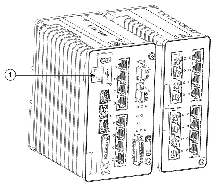
Figure 1. Connecting the Console Cable

1

RJ-45 Console Port

Step 4

Configure the baud rate and character format of the PC or terminal to match the console port characteristics:

The default characteristics are:

  • 9600 baud

  • 8 data bits

  • 1 stop bit

  • No parity

  • None (flow control)

Step 5

Connect power to the switch as described in Connecting to Power.

Step 6

The PC or terminal displays the bootloader sequence.

After the switch has finished booting press Enter to display the setup prompt.

See Initial System Configuration to configure the switch using the Setup program.


USB-C Console Port

Before you begin


Note


The USB Console port is intended only for service operation and not for continuous use.

Procedure


Step 1

Use a Phillips screwdriver to loosen the screw on the USB type C console port cover.

Remove the screw and take off the cover.
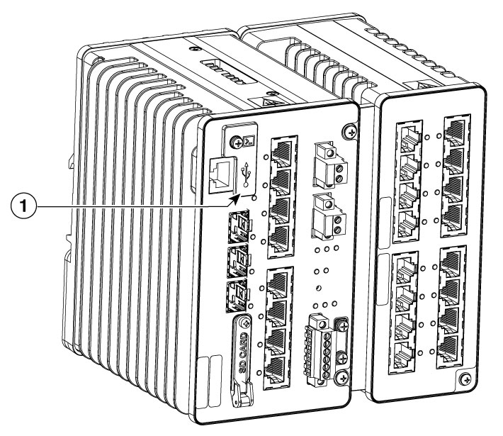
Figure 2. USB-C Console Port, Cover

1

USB-C Console Port, Cover

Step 2

Connect a USB cable to the PC USB port.

Connect the other end of the cable to the switch USB-C console port.

Step 3

Identify the COM port assigned to the USB-C console port.

Step 4

Start the terminal-emulation program on the PC.

Step 5

Configure the COM port.

Step 6

Configure the baud rate and character format of the PC or terminal to match the console port characteristics:

The default characteristics are:

  • 9600 baud

  • 8 data bits

  • 1 stop bit

  • No parity

  • None (flow control)

Step 7

Apply power to the switch as described in Connecting to Power.

Step 8

The PC or terminal displays the bootloader sequence.

Press Enter to display the setup prompt.

See Initial System Configuration to configure the switch using the Setup program.

Step 9

Place the console port cover back, hand tighten the screw.


Initial System Configuration

To set up the switch, you need to complete the setup program, which runs automatically after the switch is powered on. You must assign an IP address and other configuration information necessary for the switch to communicate with the local routers and the Internet. This information is also required if you plan to use WebUI to configure and manage the switch.

IP and Password Settings

You need this information from your network administrator before you complete the setup program:

  • Encryption level and Master key

  • Switch IP address

  • Subnet mask (IP netmask)

  • Default gateway (router)

  • Enable secret password

  • Enable password

Initial Configuration

Complete the following steps to create an initial configuration for the switch with the setup program:

Procedure


Step 1

Enter Yes at these two prompts:


Would you like to enter the initial configuration dialog? [yes/no]: yes
At any point you may enter a question mark '?' for help.
Use ctrl-c to abort configuration dialog at any prompt.
Default settings are in square brackets '[]'.
Basic management setup configures only enough connectivity
for management of the system, extended setup will ask you
to configure each interface on the system.
Would you like to enter basic management setup? [yes/no]: yes

Step 2

Enter a hostname for the switch.

On a command switch, the hostname is limited to 28 characters; on a member switch, it is limited to 31 characters. Do not use -n , where n is a number, as the last character in a hostname for any switch.

Configuring global parameters:


Enter host name [Switch]:host_name

Step 3

Enter an enable secret password.

The password can be of minimum 10 to maximum 25 alphanumeric characters, and must contain atleast one uppercase, one lower case, and a digit.

Note

 
The password should not contain the word cisco in it.

Enter enable secret: secret_password
Confirm enable secret: secret_password

Step 4

Enter an enable password.


Enter enable password: enable_password

Step 5

Enter a virtual terminal password.

The password can be from 1 to 25 alphanumeric characters, is case sensitive, allows spaces, but ignores leading spaces.


Enter virtual terminal password: terminal-password

Step 6

Enter the interface name (physical interface or VLAN name) of the interface that connects to the management network.

For this release, always use vlan1 as the interface connecting to the management network.

Note


The switch will transmit a DHCP discover message on the vlan1 interface. If the switch is connected to the network before the CLI initial setup process is started, the interface may have been assigned a dynamic IP address. If you do not see an IP address on the vlan1 interface, this process allows you set a static IP address for management. This will over write the dynamically assigned IP address.

Current interface summary

Interface                   IP-Address      OK? Method Status                Protocol
Vlan1                       10.0.113.39     YES DHCP   up                       up
GigabitEthernet1/1          unassigned      YES unset  down                    down
GigabitEthernet1/2          unassigned      YES unset  down                    down
GigabitEthernet1/3          unassigned      YES unset  down                    down
GigabitEthernet1/4          unassigned      YES unset  down                    down
GigabitEthernet1/5          unassigned      YES unset  down                    down
GigabitEthernet1/6          unassigned      YES unset  down                    down
GigabitEthernet1/7          unassigned      YES unset  down                    down
GigabitEthernet1/8          unassigned      YES unset  down                    down
GigabitEthernet1/9          unassigned      YES unset  down                    down
GigabitEthernet1/10         unassigned      YES unset  down                    down
GigabitEthernet1/11         unassigned      YES unset    up                      up
AppGigabitEthernet1/1       unassigned      YES unset    up                      up

Enter interface name used to connect to the
management network from the above interface summary: 
 vlan1

Step 7

Configure the interface by entering the switch IP address and subnet mask.

The configuration summary is displayed.

Step 8

Select option 2 to save the configuration and exit the configuration menu.


The switch can run on the default configuration. However, you can use the CLI, enter commands at the Switch> prompt to change the configuration or perform other management tasks.

Example


         --- System Configuration Dialog ---
Would you like to enter the initial configuration dialog? [yes/no]: yes

At any point you may enter a question mark '?' for help.
Use ctrl-c to abort configuration dialog at any prompt.
Default settings are in square brackets '[]'.


Basic management setup configures only enough connectivity
for management of the system, extended setup will ask you
to configure each interface on the system

Would you like to enter basic management setup? [yes/no]: yes
Configuring global parameters:

  Enter host name [Switch]: Switch

  The enable secret is a password used to protect
  access to privileged EXEC and configuration modes.
  This password, after entered, becomes encrypted in
  the configuration.
  -------------------------------------------------
  secret should be of minimum 10 characters and maximum 32 characters with
  at least 1 upper case, 1 lower case, 1 digit and
  should not contain [cisco]
  -------------------------------------------------
  Enter enable secret: **********
  Confirm enable secret: **********
Netconf SSH RSA key generated
Key Name: NETCONF_SSH_RSA_KEY
Key Type: ssh-rsa
Modulus Size: 2048
Public Key: ssh-rsa AAAAB3AAAADAQABAAABAQC46E6OfS9Tl6bHuxJkyrCy9JDwgkE9tK
XJcgD2Mu26NTCGpIDRyGAjaj9+gc04Gc/TOHruWEt/XTZu9hWK1dN+rZytJMNw3nEavFcsm+d
gDzYwh3BAi16edDil97YzlNr5bsisrgehSqKoq7Srj8fW3SyPNRU2WNdbeLkwjLtZQSgA7hBL
x1r9V+wS9+hk8SQJsMRBhMSLMo7Mo/XZ22risylZPeWvypmip6zGakKm14K8TbgnKmTbgZscp
hn/qJ9ag+tzuDQug+ZLWw/QE3MJHZmcbXdt1gcE8b0lTRT


  The enable password is used when you do not specify an
  enable secret password, with some older software versions, and
  some boot images.
  Enter enable password: **********

  The virtual terminal password is used to protect
  access to the router over a network interface.
  Enter virtual terminal password: *********

Current interface summary

Interface                   IP-Address      OK? Method Status                Protocol
Vlan1                       10.0.113.39    YES DHCP   up                        up
GigabitEthernet1/1          unassigned      YES unset  down                    down
GigabitEthernet1/2          unassigned      YES unset  down                    down
GigabitEthernet1/3          unassigned      YES unset  down                    down
GigabitEthernet1/4          unassigned      YES unset  down                    down
GigabitEthernet1/5          unassigned      YES unset  down                    down
GigabitEthernet1/6          unassigned      YES unset  down                    down
GigabitEthernet1/7          unassigned      YES unset  down                    down
GigabitEthernet1/8          unassigned      YES unset  down                    down
GigabitEthernet1/9          unassigned      YES unset  down                    down
GigabitEthernet1/10         unassigned      YES unset  down                    down
GigabitEthernet1/11         unassigned      YES unset  up                        up
AppGigabitEthernet1/1       unassigned      YES unset  up                        up

Enter interface name used to connect to the
management network from the above interface summary: Vlan1

Configuring interface Vlan1:
    IP address for this interface [10.0.113.39]:
    Subnet mask for this interface [255.0.0.0] :
    Class A network is 10.0.0.0, 8 subnet bits; mask is /8

The following configuration command script was created:

hostname Switch
enable secret 9 $9$IjMTkpAcbKRIK.$W27WanN6KUn4NnrjTTJteGEox1u.
enable password enable_password
line vty 0 15
password teminal_password
no snmp-server
!
no ip routing

!
interface Vlan1
no shutdown
ip address 22.1.1.39 255.0.0.0
!
interface GigabitEthernet1/1
!
interface GigabitEthernet1/2
!
interface GigabitEthernet1/3
!
interface GigabitEthernet1/4
!
interface GigabitEthernet1/5
!
interface GigabitEthernet1/6
!
interface GigabitEthernet1/7
!
interface GigabitEthernet1/8
!
interface GigabitEthernet1/9
!
interface GigabitEthernet1/10
!
interface GigabitEthernet1/11
!
interface AppGigabitEthernet1/1
!
end


[0] Go to the IOS command prompt without saving this config.
[1] Return back to the setup without saving this config.
[2] Save this configuration to nvram and exit.

Enter your selection [2]: 2
Building configuration...
[OK]
Use the enabled mode 'configure' command to modify this configuration.


Press RETURN to get started!