Understand Best Practices AP Auto-Locate in Spaces AnyLocate
Available Languages
Contents
Introduction
This document describes best practices and troubleshooting for AP Auto-Locate in Cisco Spaces AnyLocate.
Overview
Cisco Spaces AnyLocate (AP Auto-Locate) uses FTM ranging, GNSS (GPS) data, and AP-to-AP relative positioning to determine access point placement on floor maps.
This document provides configuration requirements, best practices, validation steps, and troubleshooting guidance to help ensure accurate AP placement and successful ranging.
Prerequisites
Requirements
Cisco recommends that you have knowledge of these topics:
Wireless LAN Controller (WLC) Validation
These configurations are mandatory for AP Auto-Locate to function correctly.
FTM and Geolocation
FTM ranging and AP geolocation must be enabled on the controller.
Refer to Cisco documentation:
-
Geolocation Derivation
These features enable AP-to-AP distance measurements and GPS-based positioning.
TDL (Telemetry) Subscriptions
TDL Subscriptions between Spaces and WLC must be Active. This is the channel through which ranging data is relayed.
- TDL Subscription number is prefixed with first 7 digits of Connector ID, suffixed with [11-21].
- Required TDL subscriptions, functions, and respective minimum WLC code versions required:
| subscription-id |
tdl-uri |
min-version-required |
| 11 |
/services;serviceName=ewlc_oper/rrmAPautoRfdot11Data |
Always present |
| 14 |
/services;serviceName=wncloudm_oper/ap_gnss_loc_data |
>=17.12.0 |
| 12 |
/services;serviceName=ewlc_oper/ap_sensor_cache |
>=17.12.0 |
| 13 |
/services;serviceName=ewlc_oper/ap_ranging_data |
>=17.12.0 |
| 17 |
/services;serviceName=ewlcevent/geo_loc_asc_meas |
>=17.12.2 |
| 18 |
/services;serviceName=ewlc_oper/cdp_cache_data |
>=17.12.0 |
| 20 |
/services;serviceName=ewlcevent/geoloc_disruptive_ranging |
>=17.13.0 |
| 21 |
/services;serviceName=ewlcevent/ap_movement |
>=17.13.0 |
| 22 |
/services;serviceName=ewlcevent/tdoa_events |
>=17.18.2 |
Validation Commands
- Show active subscriptions
show telemetry ietf subscription all- Show Subscription Details
show telemetry ietf subscription <subscription-id> receiver- Removing Subscription
(config)# no telemetry ietf subscription <subscription-id>Components Used
The information in this document is based on these software and hardware versions:
- Spaces Connector 3 - Location Service 3.1.0.94 or later
- Catalyst 9800 - Minimum version 17.12.1 (17.15 for 917x APs)
- Supported AP models - 9130, 9136, 9164, 9166
- CAD file of floormap - DWG format (Published in Spaces)
- 6 GHz must be enabled for ranging accuracy (WLAN enabled for 6GHz).
- AnyLocate is not supported for default Catalyst site tag (must place APs in new site tag).
- Use Beta UI (Edit in Spaces Home dashboard).
Upload a completed CAD file to Spaces in Locations & Maps (Rich Maps Section). It must be tied to a Location Hierarchy element which can be created from CSV method. The Rich Map generation process can take from 3 days to 2 weeks. CAD can be rejected based on layer criteria and requirements.
The information in this document was created from the devices in a specific lab environment. All of the devices used in this document started with a cleared (default) configuration. If your network is live, ensure that you understand the potential impact of any command.
NETCONF Requirement
AnyLocate uses NETCONF/SSH to poll the AP list from the controller.
NETCONF must be enabled and the current credentials must be updated in the Spaces UI. If AP list is not polled properly within 30-days, AP ranging data is purged from Spaces
GPS Validation
To validate GNSS functionality:
show gnss status-
Check the number of satellites heard by APs.
-
A minimum of 4 satellites is required for reliable GPS positioning.
-
GPS validation is best suited for cloud-side validation and anchor placement.
Best Practices
Ranging Behavior
Allow 15 minutes for neighbor tables and ranging data to populate.
Ensure at least one WLAN is active on:
-
5 GHz
-
6 GHz (recommended for improved ranging accuracy)
Ranging Scope
To avoid performance issues, site tags are configured on per-floor or per-building basis:
-
Ranging under 250 APs at a time is recommended via either of these options:
-
Per-site tag, or
-
Selected APs
-

Note: Ranging too many APs simultaneously can leave some APs without ranging data and incomplete operations.
Operational Considerations
AP ranging is performance-impacting and must be scheduled during a maintenance window.
Default FTM parameters are recommended.
Ensure CAD files are dimensionally accurate and match the physical space.
Map Service Restriction
If Catalyst Center maps exist in Cisco Spaces:
-
AnyLocate maps cannot be published to the Map Service.
-
The CatC floor map must be removed before publishing AnyLocate results.
Ranging Troubleshooting Commands
| WLC Commands |
Description |
| show ap geolocation ranging capability |
Details AP ability to participate in ranging |
| show ap geolocation summary |
Gives gnss data for all the APs |
| show ap geolocation gnss-capable summary |
Shows whether the APs are GPS-capable or not. |
| show ap geolocation ranging request |
APs to which ping request is sent and APs from which reports are received |
| show ap geolocation ranging report |
Gives complete list of all the latest and best records received from all FTM capable APs |
| show ap geolocation ranging status |
Shows AP-to-AP ranging detection with neighboring APs. |
| AP commands |
Description |
| show ap name <gray-ap-name> geo ranging status |
AP-to-AP ranging status for an AP that appears gray on the floor map |
| show spaces endpoint connection detail |
GNSS-related information at the access point (AP) level |
| show spaces endpoint key authentication |
|
| show spaces endpoint key access |
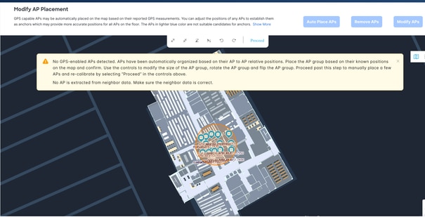
AP Placement
AP Color Key
-
Solid Blue – Anchor-possible, decided by algorithm (typically edge APs)
-
Light Blue – standard ranged AP
-
Gray – No ranging data
-
Green – Manually placed AP by user
AP Overlay
Initial placement is anchorless, based on AP-to-AP relative distances. Hence, this is not the actual position, just the cluster of APs with their relative position based on their distances.
The AP overlay could require manual rotation to align with the floor map. Use the rotation function to manually spin the full AP overlay to sit on top of the Rich maps
It is possible that the initial placement is not aligned with map orientation, but is accurate relative to AP location.
Anchor AP Requirement
Ensure the network has a minimum of 4–5 anchor APs whose locations can be determined either via GPS or manual placement based on known relative positions.
These anchor APs are used as reference points to calculate the relative positions of the remaining APs in the network.
GPS Considerations
GPS availability depends on:
-
AP model
-
Physical location
-
Proximity to windows
-
First-floor APs often have poor GPS signal quality.
Isolation and Line-of-Sight
Line-of-sight is extremely important to ranging. If an AP is isolated or has no path to be heard by other APs (at least 3), it does not generate ranging data.
Ensure the AP is mounted near a window or has a clear line of sight to the sky to allow the GPS module to obtain the satellite signal:
- It links with neighboring APs.
- When it is not ranged, user needs to manually place AP. (Displayed as gray AP).
Accuracy
Accuracy is highly dependent on the aforementioned isolation and line-of-sight factors. A review of the physical space is possibly required to confirm if APs are positioned to properly range.
Some manual intervention on AP placement is highly recommended after system placement to ensure highest degree of AP placement
AP placement has downstream effects on asset and location tracking due to RTLS requirements of AP location reference point.
Delete a Catalyst Center Floor Map Image in Cisco Spaces
- Log in to the Cisco Spaces dashboard.
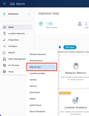
- Navigate to Setup > Map Service.
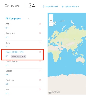
- Drill down through the location hierarchy:
- Campus > Building > Floor
Campus:
Building:
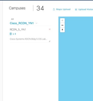
Floor:
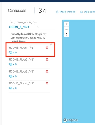
1. Select the floor you want to remove.
2. Click the Delete (trash) icon next to the floor.
3. When prompted with Are you sure you want to delete the floor?, click Yes to confirm.
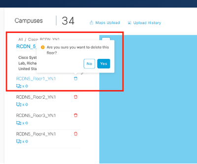
Once confirmed, the floor map image is deleted from Cisco Spaces.
Revision History
| Revision | Publish Date | Comments |
|---|---|---|
1.0 |
07-May-2026
|
Initial Release |
 Feedback
Contact Cisco
- Open a Support Case

- (Requires a Cisco Service Contract)