Configure Disjoint Layer 2 in Cisco UCS Manager
Available Languages
Contents
Introduction
This document describes how to configure Disjoint Layer 2 (DL2) in Cisco Unified Computing System Manager (UCS Manager) and how to verify that VLAN traffic uses the intended uplinks.
Environment
- At least one available link on each Fabric Interconnect and two available links on your upstream switch
- The links between the Fabric Interconnects and the upstream switch must be up and configured as uplinks. If they are not, see Cisco UCS Manager GUI Configuration Guide: Using the LAN Uplinks Manager.
- The VLANs to be used must already exist in UCS Manager. If they do not, see Cisco UCS Manager GUI Configuration Guide: Creating a Named VLAN with the LAN Uplinks Manager.
- The VLANs to be used must be created on the upstream switch already.
- The VLANs to be used cannot exist on any other virtual Network Interface Cards (vNIC) on the Service Profiles.
Requirements
Knowledge of these topics is helpful:
- Cisco Unified Computing System Manager (UCS Manager).
- Basic understanding of Disjoint Layer 2 networks.
- Networking configuration.
- vNIC configuration.
Components used
| Product |
Role |
Version/Model |
|---|---|---|
| Cisco UCS Manager |
Management platform |
4.2(3e) |
| Fabric Interconnect |
UCS fabric connectivity |
6454 |
| Cisco UCS B-Series Server |
Server under test |
B200 M5 |
| Cisco Nexus Switch |
Upstream switch |
Nexus 5672UP 16G-FC Chassis |
| Cisco Catalyst Switch |
Access/upstream switch |
WS-C3650-12X48UR-E |
Issue
Disjoint Layer 2 (DL2)
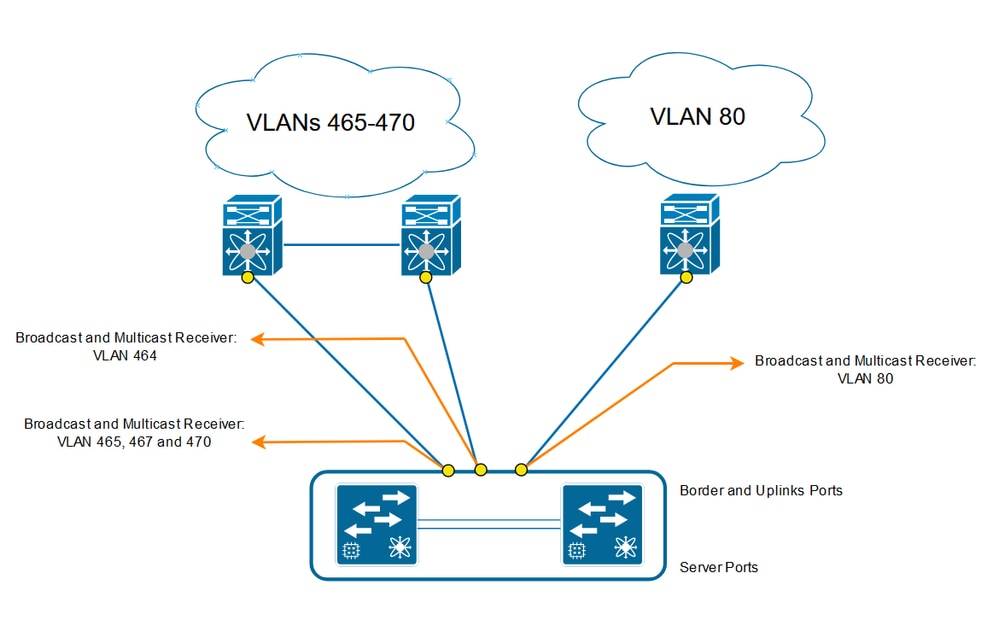
Disjoint Layer 2 (DL2) is used when two or more Ethernet networks do not connect to each other but must be accessed by servers or virtual machines in the same Cisco UCS domain.
The expected result is that each VLAN remains pinned to the correct uplink while the required Layer 2 connectivity is maintained for the associated servers or virtual machines.
Network Diagram
Resolution
Log in to the Cisco UCS Manager GUI as an administrative user.
Create Uplinks on the Fabric Interconnects
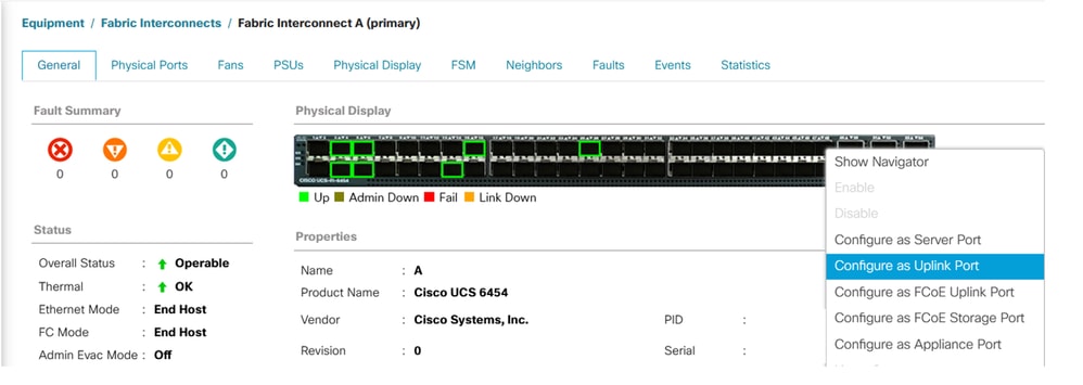
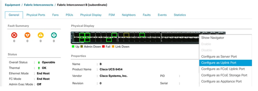
Step 1. Navigate to Equipment > Fabric Interconnects > Fabric Interconnect A or Fabric Interconnect B.
Step 2. Right-click the required port and click Configure as Uplink Port. This uplink port connects to the Disjoint Layer 2 (DL2) network. In this example, VLAN 80 is used.
Assign VLANs
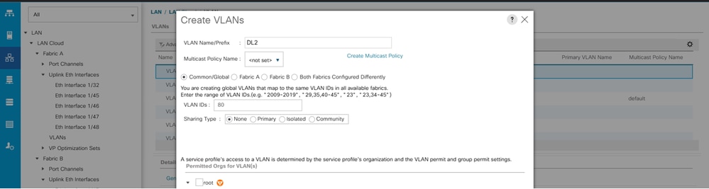
For this example, VLAN 80 was created.
Step 1. Navigate to LAN > LAN Cloud > VLANs, click Add, and complete the fields to create VLAN 80.
Create vNIC Template
Step 1. Navigate to LAN > Policies > root > vNIC Templates and click Add.
Select the vNIC template, enter a name, and select the appropriate Fabric ID.
A redundant vNIC configuration can be used.
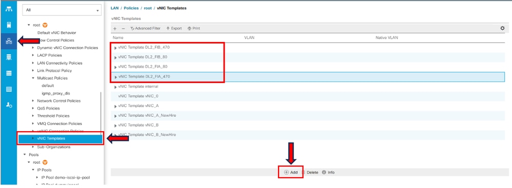
Select the VLANs to be configured accordingly. In this example, the base VLAN is VLAN 470, and the disjoint VLAN is VLAN 80.
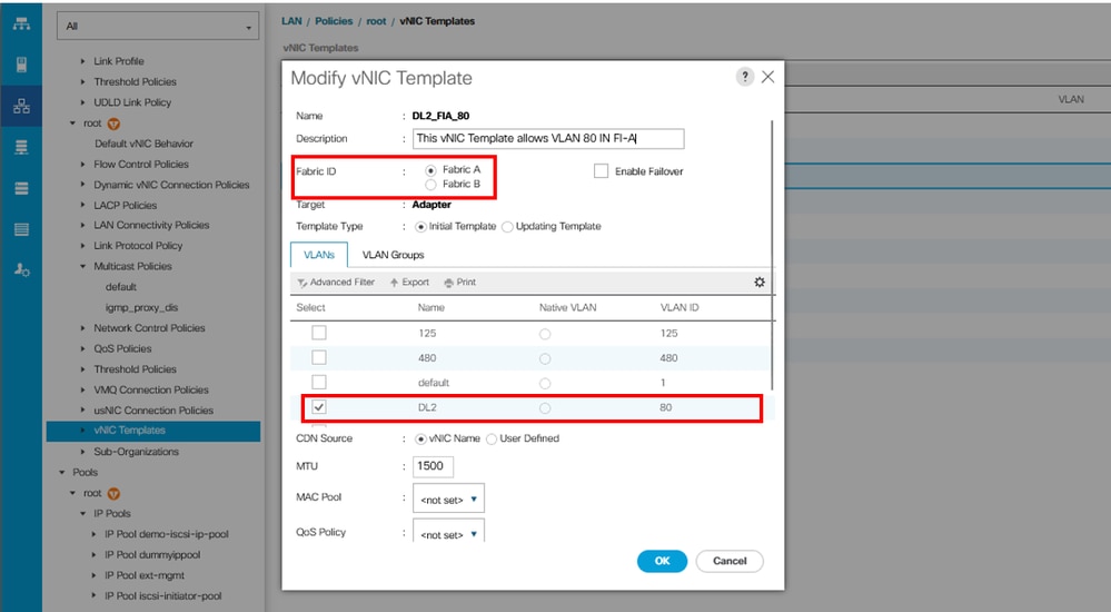
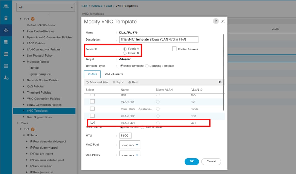
Repeat the same steps for Fabric B.
Step 2. Navigate to LAN > Policies > root > LAN Connectivity Policies, create a new policy, click Add, and create the vNICs.
Enter a name for the vNIC, select the MAC pool, and select the Use vNIC Template check box.
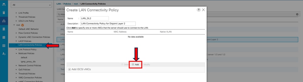
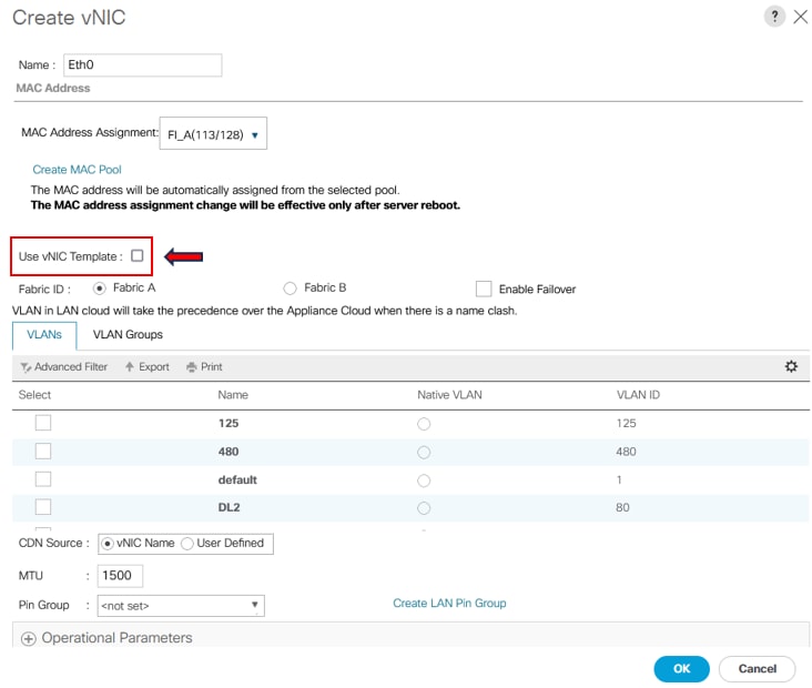
Step 3. Use the previously configured vNIC Template, select the required Adapter Policy, and click OK. Repeat this procedure for Fabric Interconnect B.
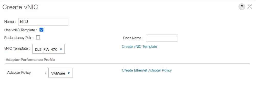
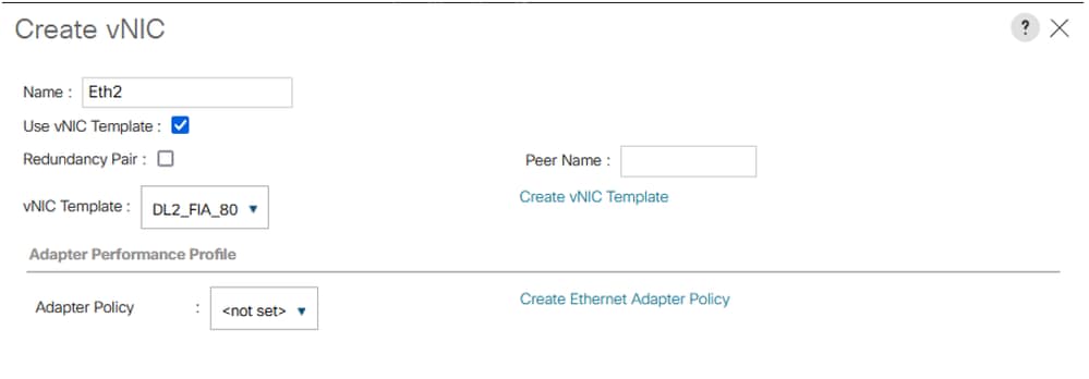
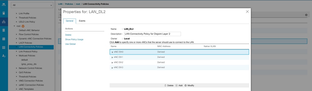
Step 4. Navigate to the Service Profile and select the LAN Connectivity Policy.
Reboot the Server
Step 1. Reboot the server to apply the configuration changes.

Note: In vCenter, ensure that the node is in maintenance mode.
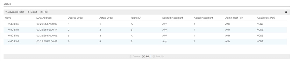
Step 2. After the server finishes booting, verify that the vNIC is present. Navigate to Servers > Service Profiles > root > service-profile-name > Network.
Create VLAN Group
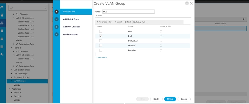
Step 1. Navigate to LAN > LAN Cloud > VLAN Groups > Create VLAN Groups.
Step 2. Enter a name for the VLAN Group, select the required VLAN, and add the individual uplinks in Step 2 of the wizard.
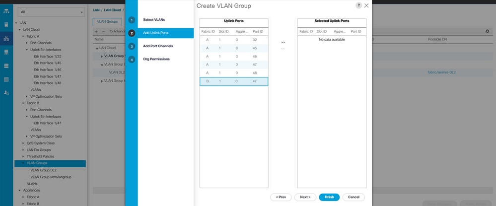
Step 3. Optionally move to Step 3 of the VLAN Group wizard to add port channels.
ESXi Configuration
Step 1. Log in to the ESXi host and navigate to the Networking tab > Virtual Switches and click Add standard virtual Switch, name the virtual switch, and select the uplink.
Step 2. Navigate to Networking > Port Group > Add Port Group. Name your port group, select the desired VLAN, and use the virtual switch previously configured.
Step 3. Navigate to Networking, select the previously configured vSwitch, and click Add Uplink. For redundancy, add a new uplink that includes the VLAN used for Disjoint Layer 2 (DL2).
In this example, VLAN 80 is allowed on vNIC Eth2 (Fabric Interconnect A) and vNIC Eth3 (Fabric Interconnect B).
Verify in UCSM
Verify the VLAN in the CLI
Open an SSH session to the Fabric Interconnects and run show vlan brief.
FI-A(nx-os)# show vlan briefThis command displays the configured VLANs and confirms the VLAN created for Disjoint Layer 2 (DL2).
VLAN Name                             Status    Ports
---- -------------------------------- --------- -------------------------------
1    default                          active    Po1, Eth1/5, Eth1/6, Eth1/8
                                                Eth1/9, Eth1/10, Eth1/11
                                                Eth1/12, Eth1/13, Eth1/16
                                                Eth1/17, Eth1/18, Eth1/19
                                                Eth1/20, Eth1/21, Eth1/22
                                                Eth1/23, Eth1/24, Eth1/26
                                                Eth1/27, Eth1/28, Eth1/29
                                                Eth1/30, Eth1/31, Eth1/32
                                                Eth1/33, Eth1/34, Eth1/35
                                                Eth1/36, Eth1/37, Eth1/38
                                                Eth1/39, Eth1/40, Eth1/41
                                                Eth1/42, Eth1/43, Eth1/44
                                                Eth1/45, Eth1/46, Eth1/47
                                                Eth1/48, Eth1/49, Eth1/50
                                                Veth876, Veth877, Veth1084
                                                Veth1119, Veth1120, Veth1122
                                                Eth1/1/10, Eth1/1/12, Eth1/1/13
                                                Eth1/1/15, Eth1/1/18, Eth1/1/20
                                                Eth1/1/22, Eth1/1/24, Eth1/1/26
                                                Eth1/1/28, Eth1/1/29, Eth1/1/30
                                                Eth1/1/31, Eth1/1/32
80   VLAN0080                         active    Eth1/47
470  VLAN0470                         active    Po1, Eth1/5, Eth1/6, Eth1/32
                                                Eth1/45, Eth1/46, Eth1/48
                                                Veth1084, Veth1090, Veth1092
                                                Veth1094, Veth1108, Veth1119
                                                Veth1120, Veth1122, Veth1131
                                                Veth1133
Verify the Virtual Interface (VIF) Path
In the SSH session, run show service-profile circuit <server number>:
FI-A# show service-profile circuit <server number>
Server: 1/6
    Fabric ID: A
        Path ID: 1
        VIF        vNIC            Link State  Oper State Prot State    Prot Role   Admin Pin  Oper Pin   Transport
        ---------- --------------- ----------- ---------- ------------- ----------- ---------- ---------- ---------
              1131 Eth0            Up          Active     No Protection Unprotected 0/0/0      0/0/1      Ether
              1133 Eth2            Up          Active     No Protection Unprotected 0/0/0      1/0/47     Ether
              1135 fc0             Up          Active     No Protection Unprotected 0/0/0      1/0/3      Fc
              9327                 Up          Active     No Protection Unprotected 0/0/0      0/0/0      Ether
    Fabric ID: B
        Path ID: 1
        VIF        vNIC            Link State  Oper State Prot State    Prot Role   Admin Pin  Oper Pin   Transport
        ---------- --------------- ----------- ---------- ------------- ----------- ---------- ---------- ---------
              1132 Eth1            Up          Active     No Protection Unprotected 0/0/0      0/0/2      Ether
              1134 Eth3            Up          Active     No Protection Unprotected 0/0/0      1/0/47     Ether
              1136 fc1             Up          Active     No Protection Unprotected 0/0/0      1/0/3      Fc
              9328                 Up          Active     No Protection Unprotected 0/0/0      0/0/0      Ether
This command displays the virtual interface (VIF) paths, the pinned interface, and the corresponding vNICs.
In this output, VIF 1134 corresponds to vNIC Eth3 and is pinned to interface 1/0/47 in Fabric Interconnect B.
Also, VIF 1133 corresponds to vNIC Eth2 and is pinned to 1/0/47 in Fabric Interconnect A.
Verify the pinning border interfaces.
Run the command to verify pinning to the uplink ports.
FI-A(nx-os)# show pinning border-interfaces

--------------------+---------+----------------------------------------
Border Interface     Status    SIFs
--------------------+---------+----------------------------------------
Po1                  Active    Veth1084 Veth1090 Veth1092 Veth1094
                               Veth1108 Veth1119 Veth1120 Veth1131
Eth1/32              Down
Eth1/45              Down
Eth1/46              Down
Eth1/47              Active    sup-eth1 Veth1133
Eth1/48              Down
Eth1/51              Down
Eth1/52              Down
Eth1/53              Down
Eth1/54              Down
Verify the Designated Receiver
Run this command to verify the port that receives multicast traffic for the VLAN.
FI-A(nx-os)# show platform software enm internal info vlandb id <VLAN-ID>
vlan_id 80
-------------
Designated receiver: Eth1/47
Membership:
Eth1/47
This output shows the correct uplink.
Verify the Upstream Switch
Open an SSH session to the upstream switch and run show vlan brief.
NEXUS-01# show vlan brief
VLAN Name                             Status    Ports
---- -------------------------------- --------- -------------------------------
1    default                          active    Po1, Po2, Po4, Po5, Po6, Po7
                                                Po8, Po9, Po50, Po100, Eth1/1
                                                Eth1/2, Eth1/3, Eth1/4, Eth1/5
                                                Eth1/6, Eth1/8, Eth1/9, Eth1/10
                                                Eth1/12, Eth1/13, Eth1/14
                                                Eth1/15, Eth1/18, Eth1/19
                                                Eth1/20, Eth1/21, Eth1/22
                                                Eth1/23, Eth1/24, Eth2/1, Eth2/2
                                                Eth2/3, Eth2/4, Eth2/5, Eth2/6
                                                Eth2/7, Eth2/8, Eth2/10, Eth2/11
                                                Eth2/12, Eth2/13, Eth2/14
                                                Eth2/15, Eth2/16, Eth2/17
                                                Eth2/18, Eth2/19, Eth2/20
                                                Eth2/21, Eth2/22, Eth2/23
                                                Eth3/1, Eth3/2, Eth3/3, Eth3/4
                                                Eth3/5, Eth3/6
                                                Eth2/18
80   DL2                              active    Po1, Po2, Po6, Po7, Po8, Po9
                                                Po50, Po100, Eth1/1, Eth1/3
                                                Eth1/4, Eth1/5, Eth1/6, Eth1/17
                                                Eth1/19, Eth1/20, Eth1/21
                                                Eth1/22, Eth1/23, Eth1/24
                                                Eth2/1, Eth2/2, Eth2/3, Eth2/4
                                                Eth2/5, Eth2/17, Eth2/18
470  VLAN_470                         active    Po1, Po2, Po3, Po4, Po5, Po6
                                                Po7, Po8, Po9, Po50, Po100
                                                Eth1/1, Eth1/3, Eth1/4, Eth1/5
                                                Eth1/6, Eth1/7, Eth1/9, Eth1/10
                                                Eth1/16, Eth1/19, Eth1/20
                                                Eth1/21, Eth1/22, Eth1/23
                                                Eth1/24, Eth2/1, Eth2/2, Eth2/3
                                                Eth2/4, Eth2/5, Eth2/9, Eth2/17
                                                Eth2/18, Eth2/24
This output shows the port associated with VLAN 80. In this example, the relevant port is Ethernet 1/17, which is associated with uplink 1/47.
The MAC address table can also be verified to confirm the virtual machine (VM) entry.
NEXUS-01(config)# show mac address-table vlan 80
Legend:
        * - primary entry, G - Gateway MAC, (R) - Routed MAC, O - Overlay MAC
        age - seconds since last seen,+ - primary entry using vPC Peer-Link
   VLAN     MAC Address      Type      age     Secure NTFY   Ports/SWID.SSID.LID
---------+-----------------+--------+---------+------+----+------------------
* 80       000c.2937.2cc7    dynamic   150        F    F  Eth1/17
Verify Connectivity to the VLAN Network in ESXi
Open the terminal in the virtual machine and ping the default gateway for the VLAN network. A successful ping confirms connectivity.
Related Content
Cisco Technical Support and Documentation
Cisco UCS Manager Network Management Guide, Release 4.0
Cisco UCS Manager GUI Configuration Guide: Using the LAN Uplinks Manager
Revision History
| Revision | Publish Date | Comments |
|---|---|---|
1.0 |
21-Jul-2023
|
Initial Release |

 Feedback
Contact Cisco
- Open a Support Case

- (Requires a Cisco Service Contract)