Configure Azure Dual ISP vWAN Connectivity on Secure Firewall
Available Languages
Contents
Introduction
This document describes how to configure Microsoft Azure Virtual WAN (vWAN) Site-to-Site VPN Connectivity to Secure Firewall using dual WAN links.
Prerequisites
Requirements
Cisco recommends knowledge of these topics:
- Microsoft Azure Virtual WAN (vWAN)
- Cisco Secure Firewall Management Center (FMC)
- Cisco Secure Firewall Threat Defense (FTD)
Ensure that these components both initially configured in the Azure environment:
- Microsoft Azure vWAN Instance
- Microsoft Azure vWAN Hub
Components Used
The information in this document is based on these software and hardware versions:
- Cisco Secure FTD Version 10.0
- Cisco Secure FMC Version 10.0
- Microsoft Azure vWAN
The information in this document was created from the devices in a specific lab environment. All of the devices used in this document started with a cleared (default) configuration. If your network is live, ensure that you understand the potential impact of any command.
Background Information
When the branch FTD has two Internet Service Provider (ISP)-facing outside interfaces, each one can connect redundantly and actively to Azure vWAN, so each ISP link is utilized. Azure vWAN creates two IPsec tunnels per Site Link — one to Azure Hub Instance0 and one to Instance1 — so each ISP interface terminates two tunnels. Across both ISP links, this results in four IPsec tunnels terminating on the FTD.
Azure Instances operate in Active/Active mode for load balancing and redundancy, so the FTD reflects this through Equal-Cost Multi-Pathing (ECMP) configuration across all four IPsec tunnels. Using custom Automatic Private IP Addressing (APIPA) addresses, external Border Gateway Protocol (eBGP) neighborships with distinct Private Autonomous System Numbers (ASNs) are established over each of the four tunnels. This enables BGP multipath functionality, providing multiple redundant paths to each Azure Hub Site Link pair of Instances.
Diagram
The diagram shows the topology of the configuration described in this article. The dual Direct Internet Access (DIA) link variant sources both Azure tunnels from two outside interface on the FTD.
Dual Direct Internet Access (DIA) Links (Azure + FTD Load-Balancing/Redundancy)
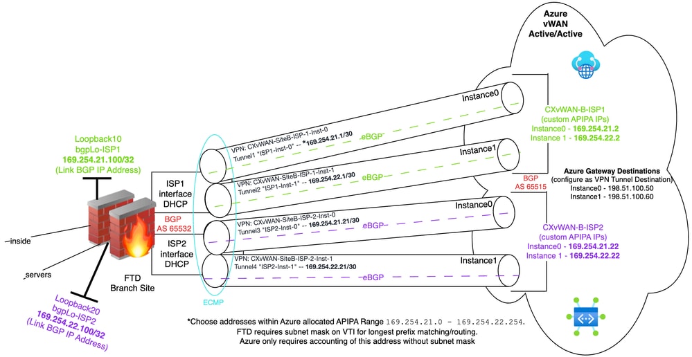 Dual Direct Internet Access Connectivity Topology
Configure
Phase 1: Azure vWAN VPN Site Configuration
Step 1: Create Azure vWAN VPN Site (Remote FTD Device)
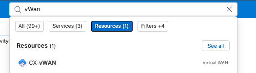
1) Search for vWAN in the Azure search field, click Virtual WANs to enter into the existing Azure vWAN Hub. Next, navigate to Connectivity > Hubs and click the existing Azure vWAN Hub.
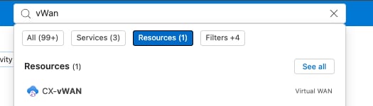 Search Query For Virtual WAN
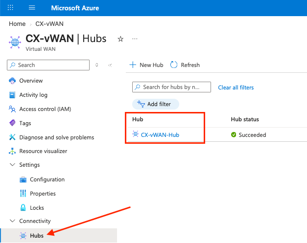 Select Existing Virtual WAN Hub
2) Click Connectivity > VPN (Site to site) and click + Create new VPN site
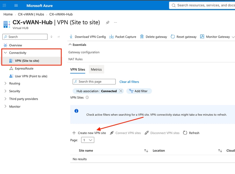 Create New Virtual WAN Site

Note: White space covering values in various fields in the images is intentional for the publishing of this document.
3) Enter the values in the required fields. When done, click Next: Links > to move forward.
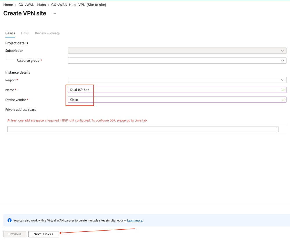 General VPN Site Configuration Settings
4) Enter the required link information. The Link BGP Address and the Link ASN are the inner-tunnel BGP Layer 3 destination address and BGP AS number on the branch side that the neighborship is formed with over the site-to-site tunnels. The Link BGP Address is a non-overlapping subnet address (/32) outside of the configured Hub private address space subnet, which Azure installs as a /32 route to reach as a BGP neighbor. Two loopback interfaces are created in later sections on the FTD to represent the Link BGP Address for each of the dual site links. The Link IP address/Fully Qualified Domain Name (FQDN) is the outer-header Layer 3 destination IP address of traffic going to the branch site necessary to provision IP Security (IPsec)/Internet Key Exchange version 2 (IKEv2) connectivity. Proceed to the next step when finished by clicking Next : Review + create >.
Note: Ensure to review specific Azure documentation if you are using addresses ranging from 169.254.21.0 to 169.254.22.255 for tunnel addresses: Choosing BGP APIPA addresses.
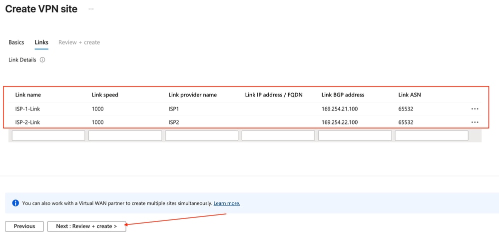 Configure Site Link Parameters
5) Once the information is confirmed as intended, click Create.
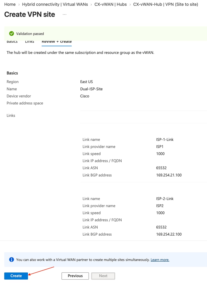 Review And Create New VPN Site
6) Once deployment of the VPN site completes, navigate back to the vWAN Hub configuration.
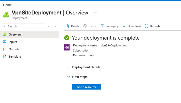 Virtual WAN Site Deployment Progress
 Search Query For Virtual WAN
Step 2: Configure Azure APIPA Gateway Parameters
Azure requires extra configuration for Automatic Private IP Addressing (APIPA) addresses within the 169.254.0.0/16 IPv4 address space.
1) Enter the existing hub via Connectivity > Hubs.
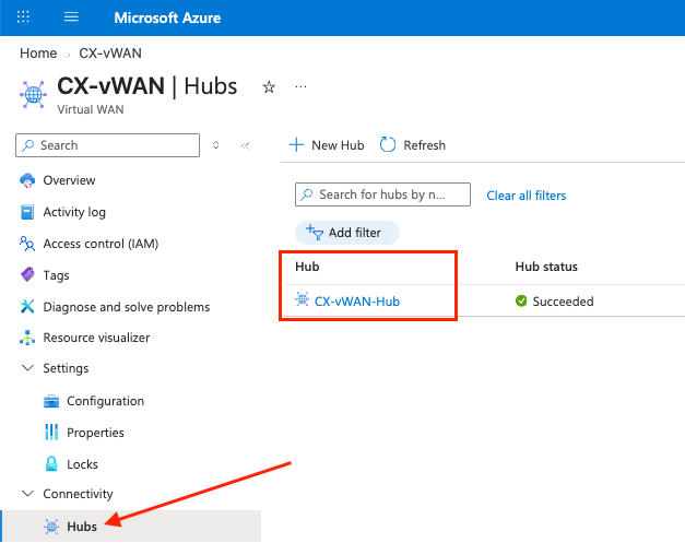 Navigate To Virtual WAN Hub Connectivity
2) Navigate once again to Connectivity > VPN (Site to site) and click the Gateway Configuration hyperlink.
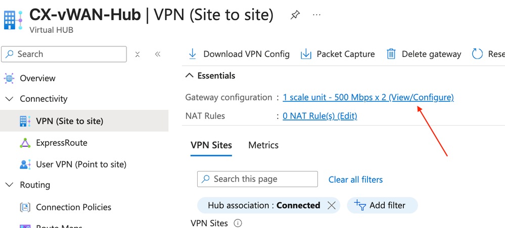 Access Gateway Configuration Hyperlink
3) A side panel appears to Edit VPN Gateway. Under VPN Gateway Instance0 and VPN Gateway Instance1, enter two unique custom BGP IP addresses that acts as neighbor IPs to each instance for BGP neighborships over the IPsec tunnels. This is necessary if you choose to use APIPA addressing within this topology. In the field labeled Peer Address, enter the BGP neighbor IP to use to reach the Azure Instances from the FTD. Azure does not attempt BGP establishment with the FTD if APIPA addressing is in use, hence the FTD attempts eBGP neighbor establishment over each tunnel with Azure.
The total comes out to 2 links x 2 implicit tunnels; one tunnel to Instance0 and Instance1 per ISP link; the total comes to four IPsec tunnels with BGP neighborships between Azure and the two FTD ISP interfaces.
These addresses must be unique, and in this demonstration, the second and final host address in the /30 subnets assigned to each tunnel is to be configured on the FTD for use. Once configured, click Edit.
Note: Ensure to review specific Azure documentation if you are using addresses ranging from 169.254.21.0 to 169.254.22.255 for tunnel addresses: Choosing BGP APIPA addresses
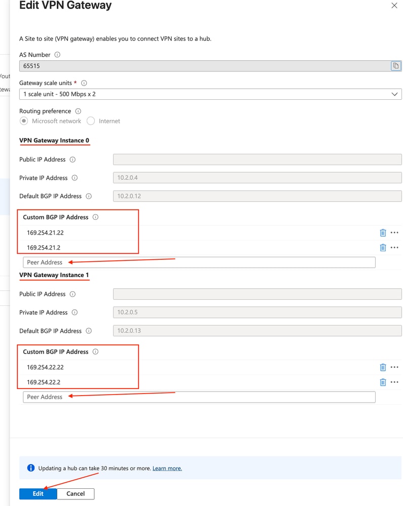 Edit VPN Gateway Custom BGP IP Addresses
Note: As Azure notes, it is possible for this to take up to 30 minutes or more to update.
Step 3: Configure Azure vWAN Site VPN Parameters
1) On the Connectivity > VPN (Site to site) page within the Azure vWAN Hub configruration, and click the X to clear the Hub Association: Connected filtering to view disconnected VPN sites.
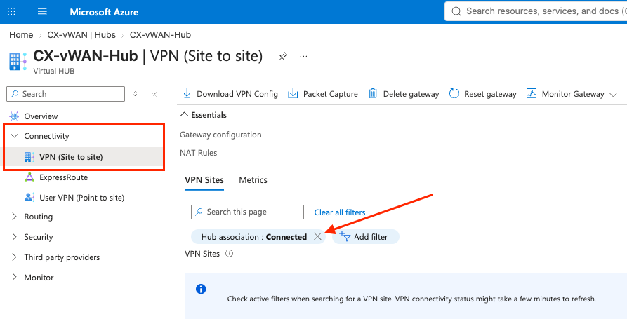 Clear Hub Association Connection Filters
2) Check the check box next to the recently provisioned VPN Site, and click Connect VPN Site.
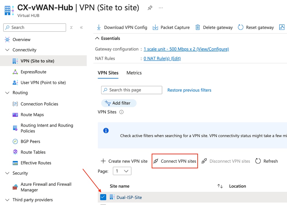 Connect VPN Site Action
3) Configure the desired Pre-Shared key (PSK), and configure desired IPsec parameters by clicking the Custom toggle option. These IPSec parameters must match on the FMC/FTD configuration in later steps. To save, click Connect.
Note: Diffie-Hellman (DH) Group 24 support was removed in FTD/FMC version 6.7.
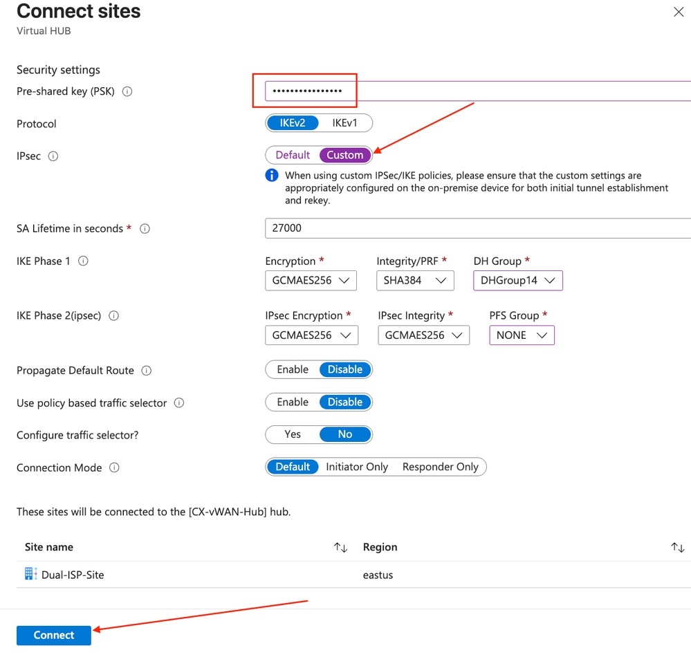 Configure Pre Shared Key And IPsec Parameters
4) Confirm VPN site provisioning completed successfully.
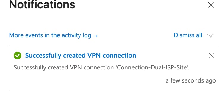 Confirm VPN Site Provisioning Status
Step 4: Enable and Activate Custom BGP APIPA on VPN Site Link Instances
1) Refresh the VPN (Site to site) page and confirm the Connection Provision status column indicates its success, which enables you to click on the ellipsis and allows you to click the Edit VPN connection to this hub drop-down menu item.
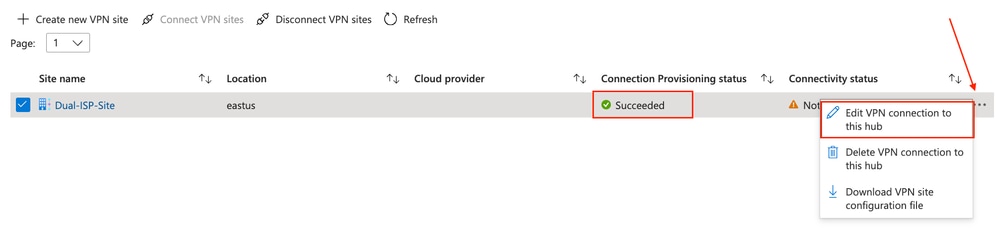 Validate Connection Sucess And Edit VPN Connection
2) Click to configure Link Connection 1 (ISP1) and enter the applicable Pre-Shared Key (PSK) again, and ensure that you click the Enable toggle next to the Custom BGP IP Address, and map what would be the remaining host address of the /30 subnets that are going to be the inner-tunnel destination IP address field values of the BGP IP header generated by the FTDs.
In essence, ISP1 VTI Tunnel1 to Azure Instance0 has an address assignment of 169.254.21.1/30, and the second ISP1 VTI Tunnel2 terminating on the FTD has an IP of 169.254.22.1/30 assigned for Instance1.
Click Next: Link Connection 2> to proceed to ISP 2 link parameters.
Note: It is possible that you need to re-enter your PSK and re-click the aligned PFS Group option in the drop-down menu in Azure.
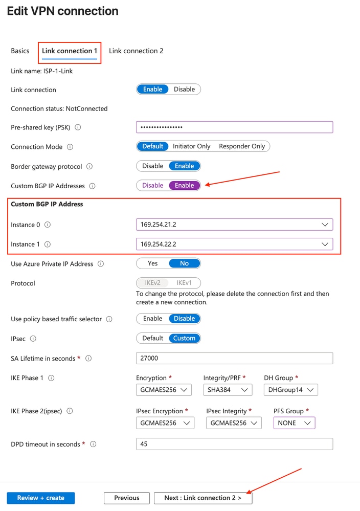 Configure Link Connection One Custom BGP Settings
3) Repeat the previous steps and apply the applicable parameters under Link Connection 2 (ISP2 link). Upon completion, click Create.
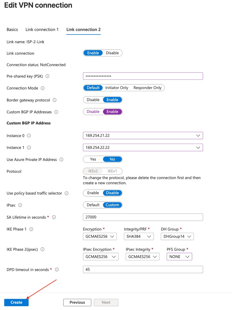 Configure Link Connection Two Custom BGP Settings
4) Notifications in Azure UI show the update task commencing.
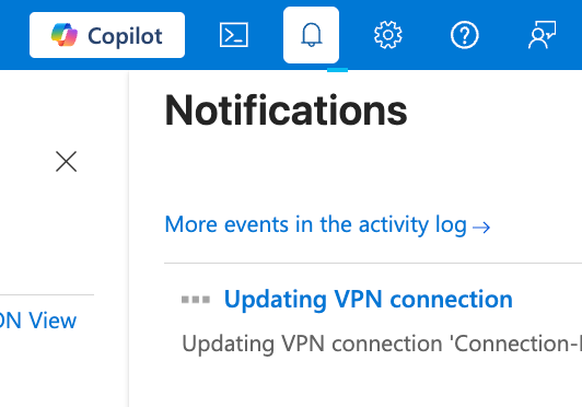 Azure Update Task Commencement Notification
Step 5: Download VPN Site Configuration File
1) In the same VPN (Site to site) page in Azure, choose the ellipsis icon on the far right of the configured VPN site and choose the Download VPN site configuration file option.
 Download VPN Site Configuration File Option
2) Click the Click here to download hyperlink.
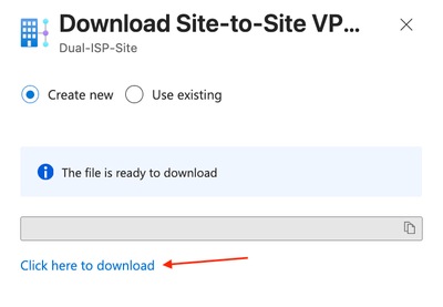 Download VPN Site Configuration File
Phase 2: Configure FTD for Dual ISP Connectivity to Azure vWAN
Step 1: Analyze the Downloaded VPN Configuration
1) Open the downloaded configuration file and a similar JavaScript Object Notation (JSON) output appears. The output shows one of the two objects written in the file. This information provides helpful context for FTD configuration.
Note: For enhanced focus, several irrelevant objects and key/value pairs are pruned for brevity.
Note: ISP-Link-1 JSON object ordering in the downloaded file is reversed. Ellipsis in the code output represents the ISP-2-Link object with its applicable configuration.
...
{
    "configurationVersion": {
      "LastUpdatedTime": "2026-09-25T20:20:26.7658453Z",
      "Version": "15221e61-4e2c-42f5-b9e4-96d674f5a9a3"
    },
    "vpnSiteConfiguration": {
      "Name": "Dual-ISP-Site",
      "IPAddress": "FTD_ISP1_WAN_IP",
      "BgpSetting": {
        "Asn": 65532,
        "BgpPeeringAddress": "169.254.21.100",
        "PeerWeight": 32768
      },
      "LinkName": "ISP-1-Link"
    },
    "vpnSiteConnections": [
      {
        "gatewayConfiguration": {
          "IpAddresses": {
            "Instance0": "Inst0IP",
            "Instance1": "Inst1IP"
          },
          "BgpSetting": {
            "Asn": 65515,
            "CustomBgpPeeringAddresses": {
              "Instance0": [
                "169.254.21.22",
                "169.254.21.2"
              ],
              "Instance1": [
                "169.254.22.22",
                "169.254.22.2"
              ]
            },
          }
        },
        "connectionConfiguration": {
          "IsBgpEnabled": true,
          "PSK": "PSK",
          "IPsecParameters": {
            "IpsecEncryption": "GCMAES256",
            "IpsecIntegrity": "GCMAES256",
            "IkeEncryption": "GCMAES256",
            "IkeIntegrity": "SHA384",
            "PfsGroup": "None",
            "DhGroup": "DHGroup14",
            "SALifeTimeInSeconds": 27000
          }
        }
      }
    ]
  }
]
Keep this output as reference as you complete the steps.
Step 2: Configure Link BGP Update Source Loopback Interfaces
BGP neighbor configuration entries under the FTD BGP process (configured in later steps on the FTD) need a stable source representing the corresponding Link BGP IP Addressin Azure Site Link configuration.
1) Navigate to Devices > Device Management.
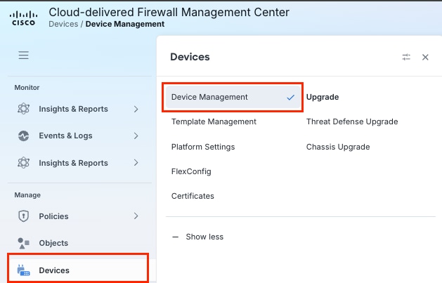 Navigate To Device Management On Firepower Management Center
Note: This lab uses cloud-delivered Firewall Management Center (cdFMC); however, the steps remain the same for on-premises FMC.
2) Click on the FTD you are configuring as the branch/site VPN device with dual ISP connectivity.
 Select The FTD For Configuration Deployment
3) Click the Add Interfaces drop-down menu, and click Loopback Interface.
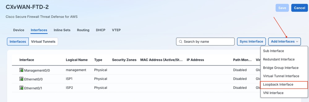 Add Loopback Interface To Device
4) Enter a Name of the loopback interface, ensure to check the Enabled check box, and enter a Loopback ID. Enter a Description if desired. Once complete, click the IPv4 tab.
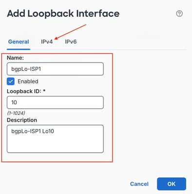 Configure Loopback Interface Information And IPv4 Address
5) Enter the loopback IP address to be the Link BGP IP address configured in earlier steps for the ISP1 site link in Azure. This IP is used as the BGP update source on the neighborships configured between the FTD and Azure Instances over ISP1.
Note: You can reference the value previously defined in the downloaded VPN config JSON under vpnSiteConfiguration.BgpSetting.BgpPeeringAddress for ISP1
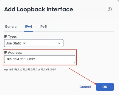 Enter Loopback IPv4 Address And Hit OK
6) Repeat sub-steps c-e in this sequence for the ISP2 BGP Loopback configuration.
 Create First And Second Loopback Interfaces
7) Save your configuration.
 Save Changes
Step 3: Configure Phase 1/Phase 2 Policy Objects
1) To configure matching IKEv2/IPsec configuration on the FMC to FTD VPN topologies, navigate to Manage > Objects, scroll in the navigation menu to VPN, and expand the sub menu. Configure the IKEv2 Phase 1 Policy by choosing IKEv2 Policy in the menu and clicking Add IKEv2 Policy.
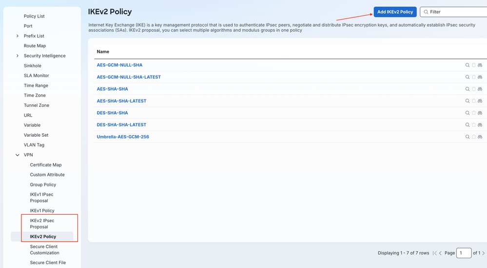 Create New IKEv2 Policy Object
2) Enter a name for the new IKEv2 Policy, choose Priority and/or Lifetime. Ensure the policy matches on both ends of the tunnel regarding Integrity, Encryption, Pseudo Random Function (PRF), and DH Group. Choose which Algorithm/Group elements to match with the Azure configuration, and click Add.
Note: You can reference these exact values within the downloaded configuration file at vpnSiteConnections[0].connectionConfiguration.IPsecParameters
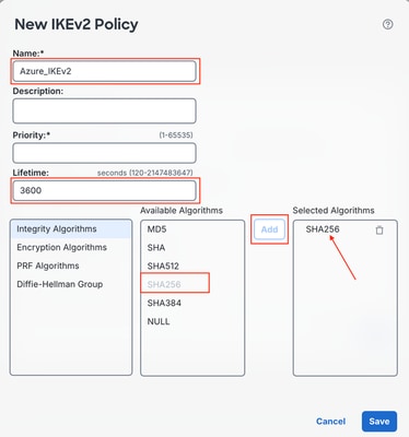 Create IKEv2 Policy
3) Once configuration is done, click Save.
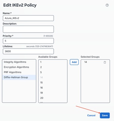 Save IKEv2 Policy
4) Configure Phase 2/IPsec parameters in the IKEv2 IPsec Proposal sub-menu and click Add IKEv2 IPsec Proposal.
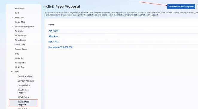 Create IKEv2 IPsec Proposal
5) Name the IKEv2 IPsec Proposal and ensure the same settings align. Once done, click Save.
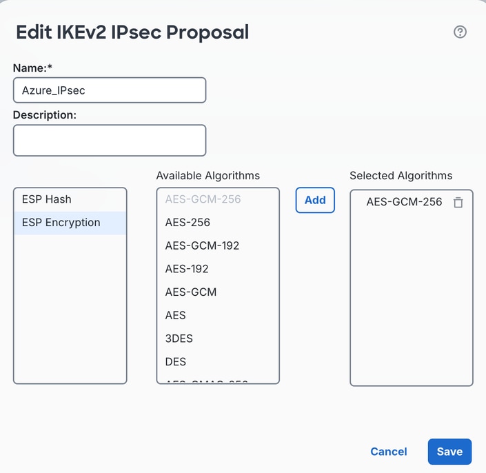 Name IKEv2 IPsec Proposal And Click Save
Step 4: Configure Virtual Tunnel Interfaces (VTI)
1) Navigate to Devices > Device Management.
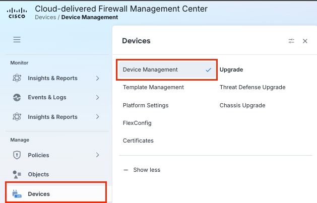 Navigate To Device Management On Firepower Management Center
2) Click the FTD you are configuring as the branch/site VPN device with dual ISP connectivity.
 Select The FTD For Configuration Deployment
3) Click the Add Interfaces drop-down menu and choose Virtual Tunnel Interface (VTI).
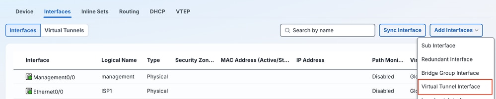 Create Virtual Tunnel Interface
4) Enter the tunnel information. Ensure the Enabled check box is checked, Name is entered (Description as well, if desired), and optional Security Zone is chosen. Align the correct parent ISP-facing interface to configure the VTI under, and configure the appropriate IP address for the inner-tunnel IPsec connectivity for the VTI. Hit OK when complete.

Tip: Reference diagram shows further context on potential VPN configuration for Azure dual-WAN connectivity with FTD.
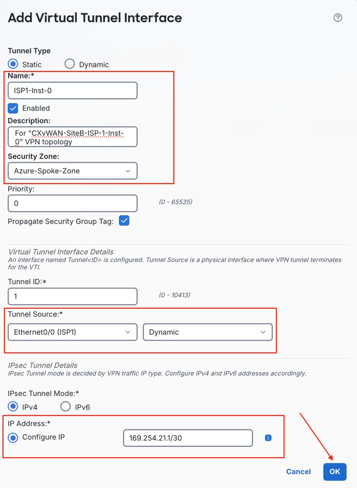 Create Virtual Tunnel Interface Settings
5) Configure 3 additional VTIs across parent ISP1 and ISP2 Interfaces.
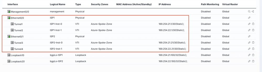 Configure Additional Virtual Tunnel Interfaces
f) Ensure to click Save to save your changes.
 Save Changes
Step 5: Provision IPsec VPN Topologies
1) Navigate to Manage > Secure Connections > Site-to-Site VPN & SD-WAN.
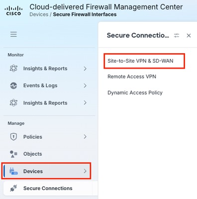 Manage Site To Site VPN And SD-WAN Connections
2) Click either the initial VPN Topology configuration hyperlink in the middle of the initial output, or click the Add button.
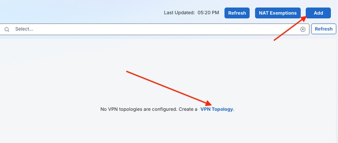 Add New VPN Topology Configuration
3) Enter a Topology name for the first tunnel over ISP1 link to Azure Instance0. Click the Route-Based VPN radio button, and click the Peer to Peer VPN topology type. Once completed, click Create.
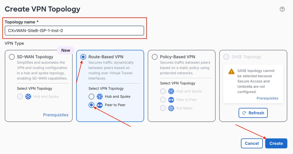 Configure Route Based VPN Topology Type
4) First, choose the Node A device and under the Device drop-down list signifying the FTD terminating the VPN tunnels from Azure. After the wizard fetches the available VTIs from the device, select the VTI appropriate to the parent interface and instance you are configuring from the drop-down menu. From the Node B Device menu, choose the Azure side to be the Extranet node in the VPN topology configuration. Ensure that you configure a friendly name for Node B, as well as ensuring to enter the appropriate Endpoint IP Address. Once complete, click the IKE tab to implement Phase 1 tunnel configuration.
Note: You can reference Instance Endpoint IP Address values in the downloaded configuration file at vpnSiteConnections[0].gatewayConfiguration.IpAddresses.Instance0 and vpnSiteConnections[0].gatewayConfiguration.IpAddresses.Instance1
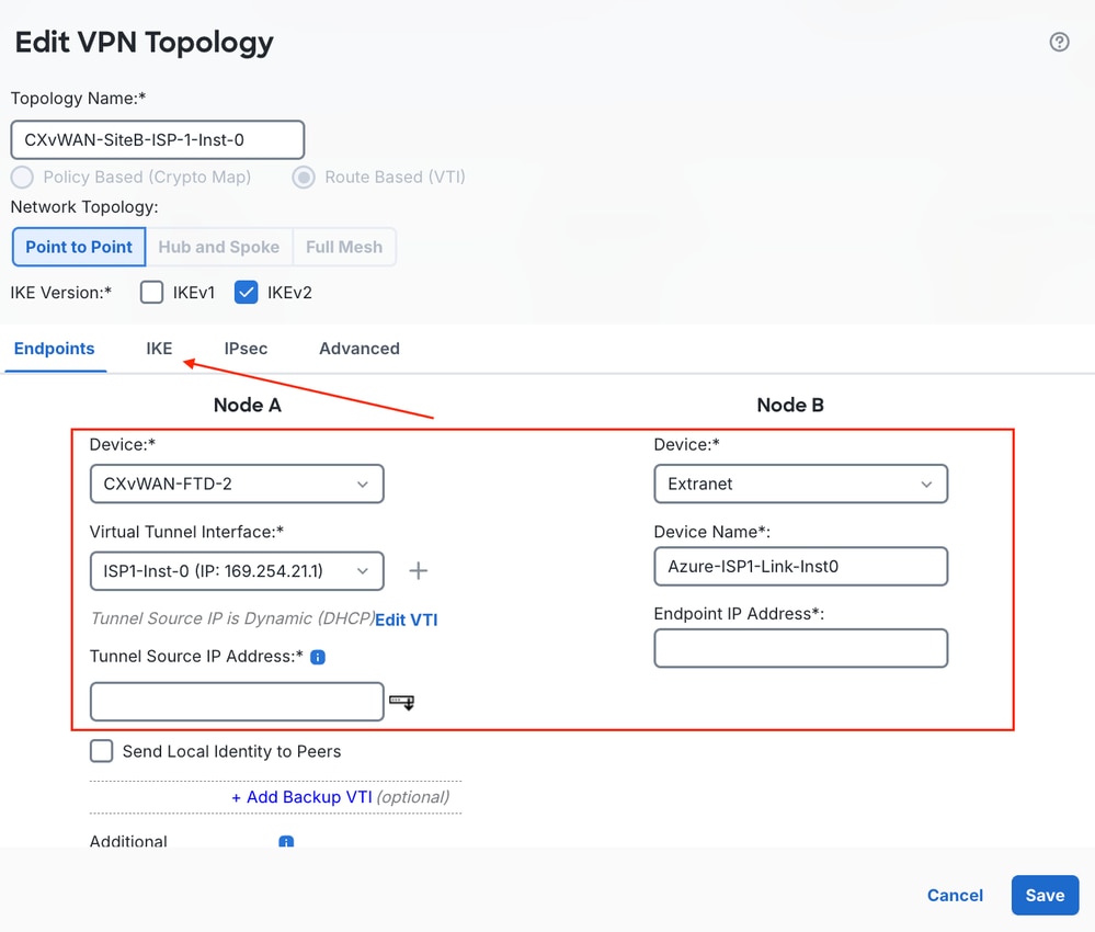 Define Node A And Node B Topology Endpoints
5) Scroll in the navigation menu to IKEv2 Settings and click the pencil icon to edit the policies to the recently configured IKEv2 Policy. Next, choose the Pre-shared Manual Key option from the Authentication Type drop-down menu, and enter the PSK previously configured in Azure. Once complete, click the IPsec tab to configure Phase 2 IPsec tunnel parameters.
Note: You can reference the pre-shared key in the downloaded configuration file at vpnSiteConnections[0].connectionConfiguration.IPsecParameters.PSK
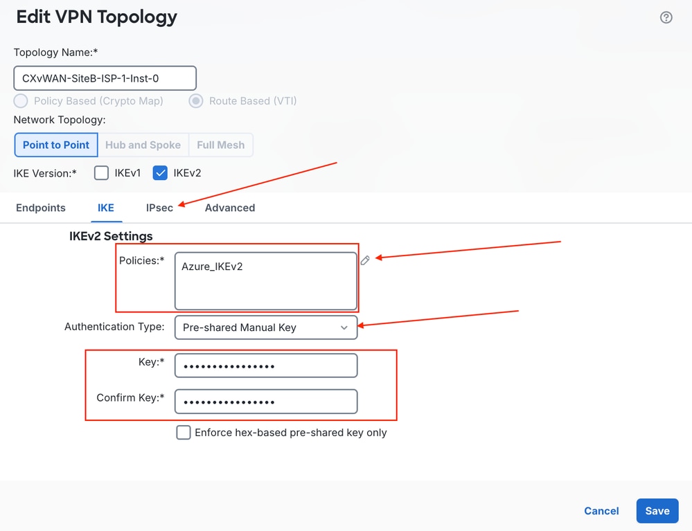 Edit IKEv2 Settings And Authentication Key
6) Click the pencil icon adjacent to the IKEv2 IPsec Proposal Transform Set, and choose the previously configured IPsec policy parameters. Ensure to change the Lifetime Duration value to match Azure vWAN VPN settings. Once configured information is confirmed, click Save.
Note: You can reference the Lifetime value in the downloaded configuration file at vpnSiteConnections[0].connectionConfiguration.IPsecParameters.SALifeTimeInSeconds
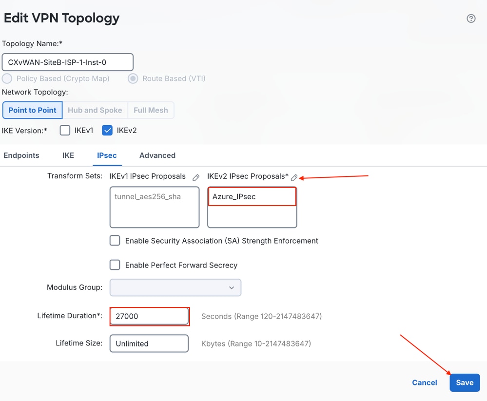 Configure IPsec Proposal Lifetime Duration
7) Repeat the previous sub-steps within Step 5 to create the other Azure Tunnels across ISP1 Instance1, ISP2 Instance0, and ISP2 Instance1.
 Create Additional Site To Site VPN Topologies
Step 6: Validate VPN Topologies
Enter into system support diagnostic-cli, type en and hit enter (read-only CLI).
1) Check IKE Phase 1 Tunnel connectivity.
`show crypto isakmp sa | i UP|READY`
2) Check IPsec Phase 2 connectivity.
show crypto ipsec sa | i int|current_peer|pkts
Note: When viewing IPsec Security Associations (SA) output and pkts decaps and pkts decrypt counters are incrementing, but pkts encaps and pkts encrypt are not, this is expected in this scenario. Azure is trying to form BGP neighborships over the Hub Private IP Space addresses, and Azure does not initiate negotiation if the neighboring end uses APIPA BGP addressing. It is the responsibility of the device connecting to Azure to initiate BGP negotiation when custom APIPA is used.
3) Check Layer 2 Connectivity.
show arp
4) Check IP Routing.
show route
5) Perform Capture on ISP1 and ISP2 interfaces.
capture isp1 interface ISP1 match udp any any eq 500
capture isp1 interface ISP1 match udp any any eq 4500
capture isp1 interface ISP1 match esp any any
...
show cap
show cap isp1
show cap isp2
6) Azure Verification - Navigate to vWAN Hub > Connectivity.> VPN Sites > Choose the site configured.
 Azure Link Connecivity Verification
Step 7: Configure ECMP
1) Navigate to Manage > Devices > Device Management and click the FTD.
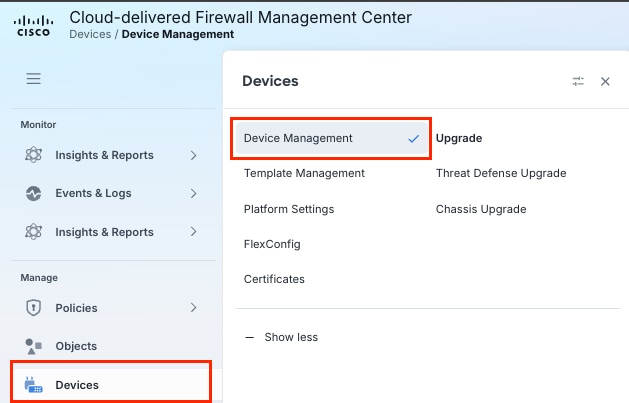 Navigate To Device Management On Firepower Management Center
 Select The FTD For Configuration Deployment
2) Click the Routing tab and choose ECMP.
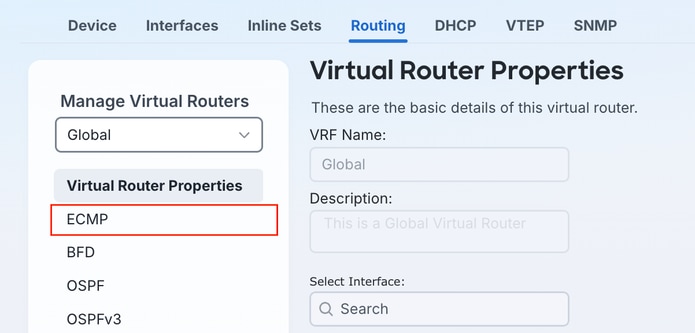 Equal Cost Multi Path Configuration Settings
3) Click Add.
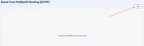 Add Equal Cost Multi Path Configuration Settings
4) Name the ECMP Zone, and click the available VTI Interfaces, then click the Add button to apply them to the Selected Interfaces column and click OK.
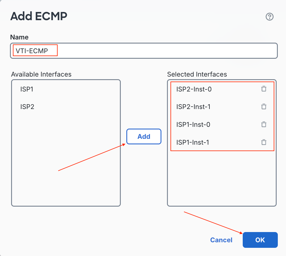 Select Interfaces For Equal Cost Multi Path Zone
5) Ensure to Save your changes.
 Save Changes
Step 8: Configure BGP
1) Enable BGP Process on the FTD under Routing > General Settings > BGP. Check the Enable BGP check box, and enter the AS number configured earlier in Phase 1, Step 1d. Navigate next to Routing > BGP > IPv4.
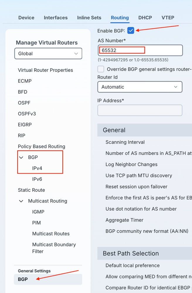 Enable Border Gateway Protocol Process Under General Settings
2) Ensure to check the Enable IPv4 checkbox for the BGP process, and click Neighbor to configure BGP neighbors in Azure.
 Enable IPv4 Border Gateway Protocol Process
3) Click + Add.
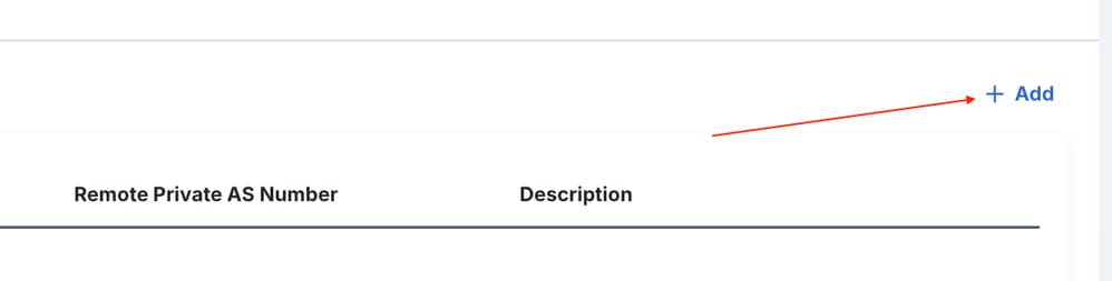 Add New Border Gateway Protocol Neighbor
4) Enter the ISP1 Instance0 BGP peering information, reference the noted BGP AS from the vWAN Hub and enter it as the Neighbor Remote AS, and add a Description if desired. Click Advanced.
Note: Ensure that you choose the BGP Update Source to reference the Loopback for VTI interfaces on the FTD mapped to the ISP1 Link configured in Azure.
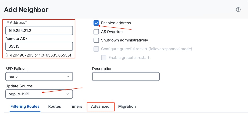 Configure Border Gateway Protocol Peering Information
5) Within the Advanced menu of BGP Neighbor configuration on FTD, you can change the number of Time To Live (TTL) hops from eBGP default of 1 hop to a variable number. Azure BGP endpoints are not directly connected over the tunnel into Azure infrastructure, and there tend to be more hops to the endpoint than the default eBGP TTL of 1 permits. Click OK.
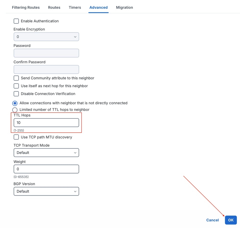 Advanced Border Gateway Protocol Neighbor Settings
6) Repeat sub-steps 3-5 to configure Tunnel2 for ISP1 Instance1.
7) Repeat sub-steps 3-5 twice to configure the ISP2 Instance0/Instance1 BGP peering information.
Note: Ensure that you choose the aligned BGP Update Source referencing the Loopback for VTI interfaces on the FTD mapped to the ISP2 Link configured in Azure.
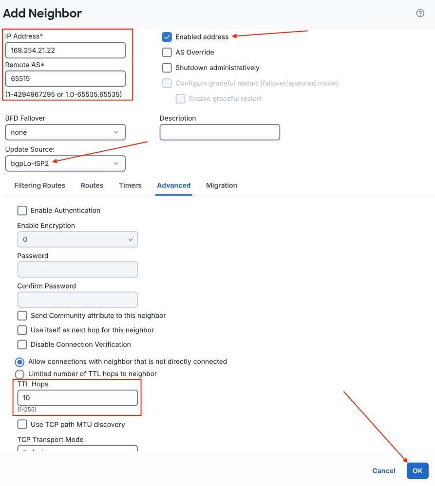 ISP2 Instance 1 BGP Neighbor Configuration
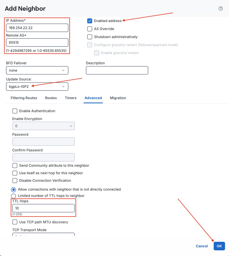 ISP 2 Instance 2 BGP Neighbor Configuration
 End BGP Neighbor Result Configuration
 Save Changes
By default, BGP installs only a single best path in the routing table, even though ECMP is configured across all VTIs to Azure. BGP multipath must be enabled separately so that both learned paths are installed and used at the same time.
Step 9: Configure eBGP Multipath
1) Navigate to Routing > BGP > IPv4, click the General tab, and click the pencil icon adjacent to Forward Packets Over Multiple Paths.
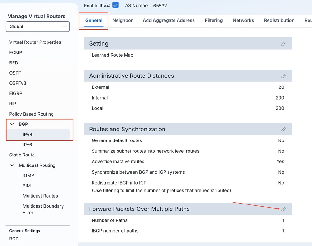 Forward Packets Over Multiple Paths Setting
2) Change the Number of Paths field default value from 1 to 4. Click OK.
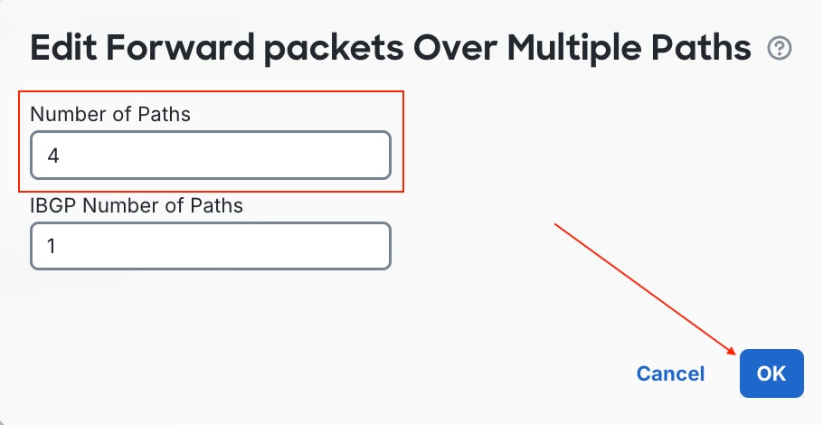 Change Forward Packets Over Multiple Paths Setting
3) Ensure that you Save and deploy the changes.
Verify/Troubleshoot
After the deployment completes, confirm that the FTD BGP process establishes neighbor adjacencies with both Azure instances on the respective tunnels, and that routes are learned, interfaces are up, and protocol connections are returned in the connection table.
Navigate to system support diagnostic-cli on FTD CLI as done in Phase 2, Step 7.
1) Once deployed, BGP neighbors are expected to come up and prefixes are received.
> system support diagnostic-cli
Attaching to Diagnostic CLI ... Press 'Ctrl+a then d' to detach.
Type help or '?' for a list of available commands.
ftd#
ftd#
ftd# show bgp summary
BGP router identifier 169.254.22.100, local AS number 65532
BGP table version is 29, main routing table version 29
2 network entries using 400 bytes of memory
8 path entries using 640 bytes of memory
2 multipath network entries and 8 multipath paths
1/1 BGP path/bestpath attribute entries using 208 bytes of memory
1 BGP AS-PATH entries using 24 bytes of memory
0 BGP route-map cache entries using 0 bytes of memory
0 BGP filter-list cache entries using 0 bytes of memory
BGP using 1272 total bytes of memory
BGP activity 4/2 prefixes, 16/8 paths, scan interval 60 secs

Neighbor V AS MsgRcvd MsgSent TblVer InQ OutQ Up/Down State/PfxRcd
169.254.21.2 4 65515 20 17 29 0 0 00:13:14 2
169.254.22.2 4 65515 20 20 29 0 0 00:13:22 2
169.254.21.22 4 65515 19 21 29 0 0 00:13:19 2
169.254.22.22 4 65515 20 19 29 0 0 00:13:17 2
ftd#
2) Check that routes received from Azure show as multipath routes.
ftd# show bgp

BGP table version is 29, local router ID is 169.254.22.100
Status codes: s suppressed, d damped, h history, * valid, > best, i - internal,
              r RIB-failure, S Stale, m multipath
Origin codes: i - IGP, e - EGP, ? - incomplete

   Network          Next Hop        Metric LocPrf Weight  Path
*m 10.2.0.0/16      169.254.21.2                       0  65515 i
*m                  169.254.22.22                      0  65515 i
*m                  169.254.21.22                      0  65515 i
*>                  169.254.22.2                       0  65515 i
*m 172.27.0.0       169.254.21.2                       0  65515 i
*m                  169.254.22.22                      0  65515 i
*m                  169.254.21.22                      0  65515 i
*>                  169.254.22.2                       0  65515 i
3) Check routing table population.
ftd# show route bgp

Codes: L - local, C - connected, S - static, R - RIP, M - mobile, B - BGP
       D - EIGRP, EX - EIGRP external, O - OSPF, IA - OSPF inter area
       N1 - OSPF NSSA external type 1, N2 - OSPF NSSA external type 2
       E1 - OSPF external type 1, E2 - OSPF external type 2, V - VPN
       i - IS-IS, su - IS-IS summary, L1 - IS-IS level-1, L2 - IS-IS level-2
       ia - IS-IS inter area, * - candidate default, U - per-user static route
       o - ODR, P - periodic downloaded static route, + - replicated route
       SI - Static InterVRF, BI - BGP InterVRF
Gateway of last resort is 172.31.3.33 to network 0.0.0.0

B        10.2.0.0 255.255.0.0 [20/0] via 169.254.22.22, 00:20:53
                              [20/0] via 169.254.22.2, 00:20:53
                              [20/0] via 169.254.21.22, 00:20:53
                              [20/0] via 169.254.21.2, 00:20:53
B        172.27.0.0 255.255.0.0 [20/0] via 169.254.22.22, 00:20:53
                                [20/0] via 169.254.22.2, 00:20:53
                                [20/0] via 169.254.21.22, 00:20:53
                                [20/0] via 169.254.21.2, 00:20:53
4) Check connection table for BGP sessions.
ftd# show conn all | include TCP|179
TCP ISP2-Inst-0  169.254.21.22:179 bgpLo-ISP2  169.254.22.100:1603, idle 0:00:10, bytes 1517, flags UIO
TCP ISP2-Inst-1  169.254.22.22:179 bgpLo-ISP2  169.254.22.100:41883, idle 0:00:01, bytes 1486, flags UIO
TCP ISP1-Inst-1  169.254.22.2:179 bgpLo-ISP1  169.254.21.100:3804, idle 0:00:53, bytes 1467, flags UIO
TCP ISP1-Inst-0  169.254.21.2:179 bgpLo-ISP1  169.254.21.100:61287, idle 0:00:04, bytes 1331, flags UIO
TCP bgpLo-ISP1  169.254.22.2:179 NP Identity Ifc  169.254.21.100:3804, idle 0:00:53, bytes 751, flags UI
TCP bgpLo-ISP2  169.254.21.22:179 NP Identity Ifc  169.254.22.100:1603, idle 0:00:10, bytes 844, flags UI
TCP bgpLo-ISP2  169.254.22.22:179 NP Identity Ifc  169.254.22.100:41883, idle 0:00:01, bytes 751, flags UI
TCP bgpLo-ISP1  169.254.21.2:179 NP Identity Ifc  169.254.21.100:61287, idle 0:00:04, bytes 639, flags UI
Revision History
| Revision | Publish Date | Comments |
|---|---|---|
1.0 |
15-Oct-2026
|
Initial Release |

 Feedback
Contact Cisco
- Open a Support Case

- (Requires a Cisco Service Contract)