Configure Secure Access with Secure Firewall with HA
Available Languages
Contents
Introduction
This document describes how to configure Secure Access with Secure Firewall with High Availability (HA).
Prerequisites
- Configure User Provisioning
- ZTNA SSO Authentication Configuration
- Configure Remote Access VPN Secure Access
Requirements
Cisco recommends that you have knowledge of these topics:
- Firepower Management Center 7.2
- Firepower Threat Defence 7.2
- Secure Access
- Cisco Secure Client - VPN
- Cisco Secure Client - ZTNA
- Clientless ZTNA
Components Used
The information in this document is based on:
- Firepower Management Center 7.2
- Firepower Threat Defence 7.2
- Secure Access
- Cisco Secure Client - VPN
- Cisco Secure Client - ZTNA
The information in this document was created from the devices in a specific lab environment. All of the devices used in this document started with a cleared (default) configuration. If your network is live, ensure that you understand the potential impact of any command.
Background Information
Cisco has designed Secure Access to protect and provide access to private applications, both on-premise and cloud-based. It also safeguards the connection from the network to the Internet. This is achieved through the implementation of multiple security methods and layers, all aimed at preserving the information as they access it via the cloud.
Network Diagram

Configure
Configure the VPN on Secure Access
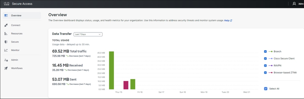
Navigate to the admin panel of Secure Access.
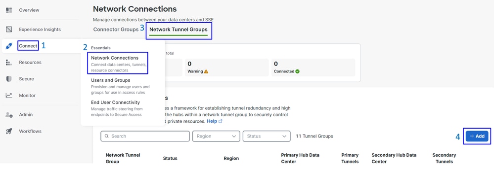
- Click on
Connect>Network Connections.
- Under
Network Tunnel Groupsclick on+ Add.
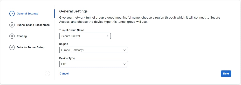
- Configure
Tunnel Group Name,RegionandDevice Type. - Click
Next.
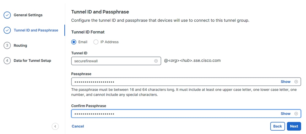
- Configure the
Tunnel ID FormatandPassphrase. - Click
Next.
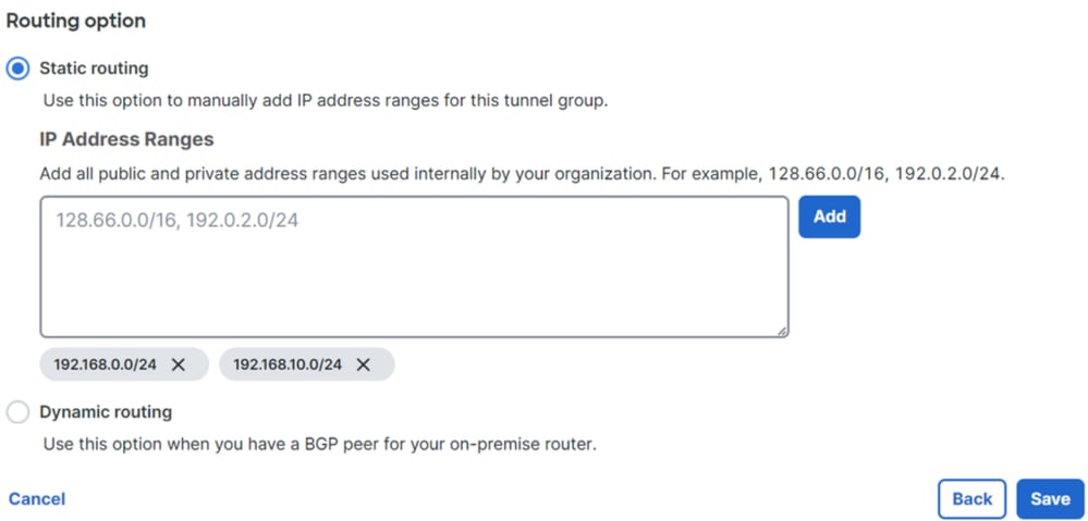
- Configure the IP address ranges or hosts that you have configured on your network and want to pass the traffic through Secure Access.
- Click
Save.
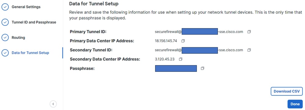
After you click Save, the information on the tunnel is displayed. Please save that information for the next step; Configure the tunnel on Secure Firewall.
Data for Tunnel Setup
Configure the tunnel on Secure Firewall
Configure the Tunnel Interface
For this scenario, you must use the Virtual Tunnel Interface (VTI) configuration on the Secure Firewall to achieve this goal; remember, in this case, you have a double ISP, and you want HA (High Availability) if one of your ISPs fails.
| INTERFACES |
ROLE |
| PrimaryWAN |
Principal Internet WAN |
| SecondaryWAN |
Secondary Internet WAN |
| PrimaryVTI |
Linked to send the traffic through the |
| SecondaryVTI |
Linked to send the traffic through the |

Note: 1. You need to add or assign a static route to the Primary or Secondary Datacenter IP to have both tunnels up.
Note: 2. If you have ECMP configured between interfaces, you do not need to create any static route to the Primary or Secondary Datacenter IP to have both tunnels up.
Based on this scenario, you have the PrimaryWAN and SecondaryWAN, which you must use to create the VTI interfaces.
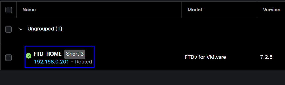
Navigate to your Firepower Management Center > Devices.
- Choose your FTD
- Choose
Interfaces

- Click on
Add Interfaces > Virtual Tunnel Interface
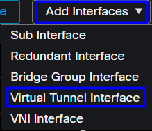
- Configure the Add Virtual Tunnel interface.
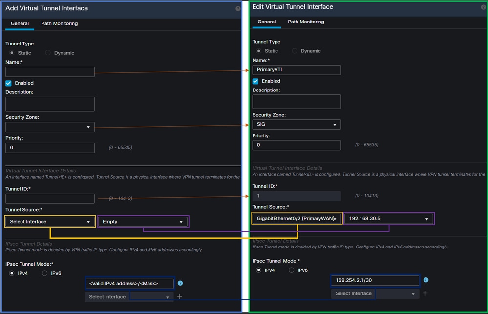
Name: Configure a name that refers to thePrimaryWAN interface.Security Zone: You can reuse anotherSecurity Zone, however, creating a new one for Secure Access traffic is best.Tunnel ID: Add a number for the Tunnel ID.Tunnel Source: Choose yourPrimaryWAN interfaceand select a private or public IP for your interface.IPsec Tunnel Mode: ChooseIPv4and configure a non-routable IP in your network with mask 30.
Note: For the VTI interface, you must use a non-routable IP; for example, if you have two VTI interfaces, you can use 169.254.2.1/30 for the PrimaryVTI and 169.254.3.1/30 for the SecondaryVTI.
After that, you must do the same for the SecondaryWAN interface. Now, your VTI High Available is set up, as a result your interface displays:
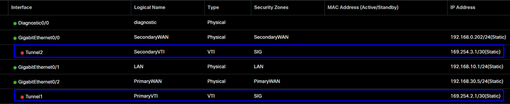
For this scenario, the IPs used are:
| Logical Name |
IP |
Range |
| PrimaryVTI |
169.254.2.1/30 |
169.254.2.1-169.254.2.2 |
| SecondaryVTI |
169.254.3.1/30 |
169.254.3.1-169.254.3.2 |
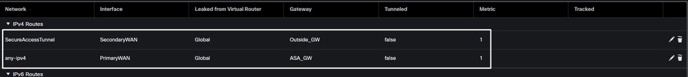
Configure Static Route for the Secondary Interface
To permit the traffic of the SecondaryWAN interface to reach the Secondary Datacenter IP Address you must configure a static route to the data center IP. You can configure it with a metric of one (1) to make it on top of the routing table; also, specify the IP as a host.

Caution: This is only required if you do not have an ECMP set up between the WAN channels; if you have an ECMP configured, you can move to the next step.
Navigate to Device > Device Management
- Click your FTD device
- Click on
Routing - Choose
Static Route > + Add Route

Interface: Choose the SecondaryWAN InterfaceGateway: Choose the SecondaryWAN GatewaySelected Network: Add the Secondary Data Center IP as a host, you can find the information when you configure the tunnel on the Secure Access step, Data for Tunnel SetupMetric: Use one (1)- Click
OKandSave, then deploy.
Configure the VPN to Secure Access in VTI Mode
To configure the VPN, navigate to your firewall:
- Click on
Devices > Site to Site - Click on
+ Site to Site VPN
Endpoints Configuration
To configure the endpoints step, you must use the information provided under the step, Data for Tunnel Setup.
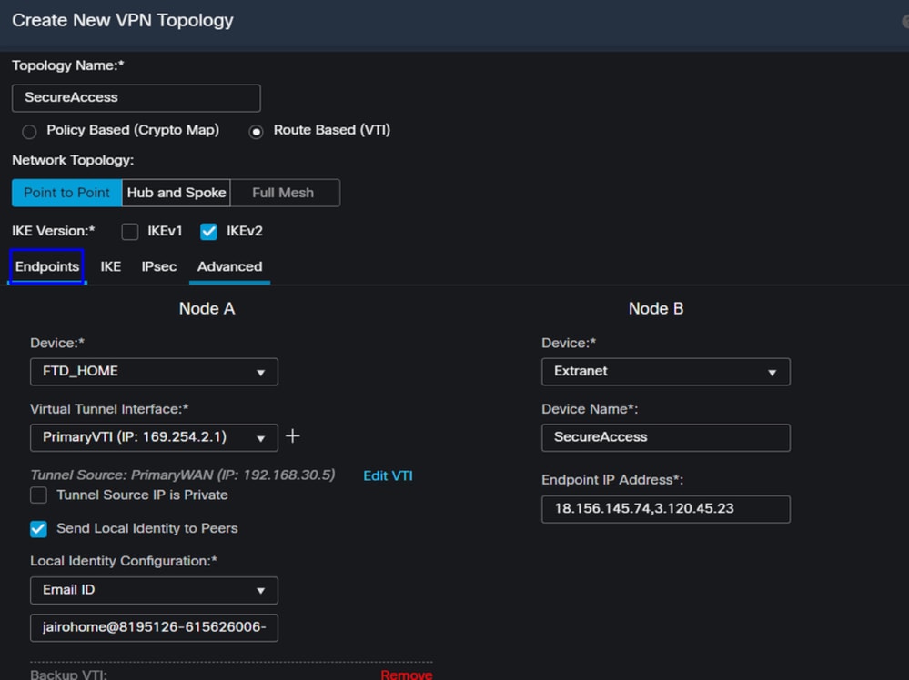
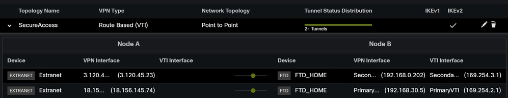
- Topology Name: Create a name related to the Secure Access integration
- Choose
Routed Based (VTI) - Choose
Point to Point IKE Version: Choose IKEv2
Note: IKEv1 is not supported for integration with Secure Access.
Under Node A, you must configure the next parameters:
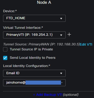
Device: Choose your FTD deviceVirtual Tunnel Interface: Choose the VTI related to thePrimaryWAN Interface- Mark the checkbox for
Send Local Identity to Peers Local Identity Configuration: Choose Email ID, and fill in the information based on thePrimary Tunnel IDprovided in your configuration on the step, Data for Tunnel Setup
After you configure the information on the PrimaryVTI click on + Add Backup VTI:
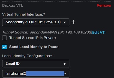
Virtual Tunnel Interface: Choose the VTI related to thePrimaryWAN Interface- Mark the checkbox for
Send Local Identity to Peers Local Identity Configuration: Choose Email ID, and fill in the information based on theSecondary Tunnel IDprovided in your configuration on the step, Data for Tunnel Setup
Under the Node B, you need to configure the next parameters:
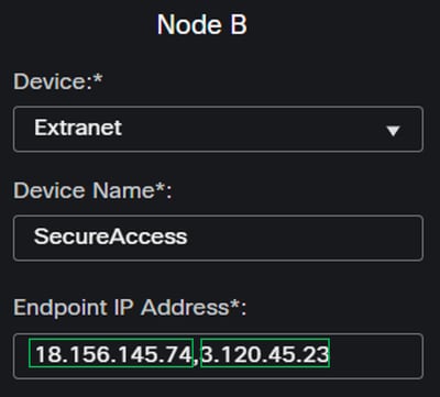
Device: ExtranetDevice Name: Choose a name to recognize the Secure Access as the destinationEndpoint IP Address: The configuration for primary and secondary must be PrimaryDatacenter IP,Secondary Datacenter IP, you can find that information in the step, Data for Tunnel Setup
After that, your configuration for Endpoints is completed.
IKE Configuration
To configure the IKE parameters, click on IKE.

Under IKE, you must configure the next parameters:
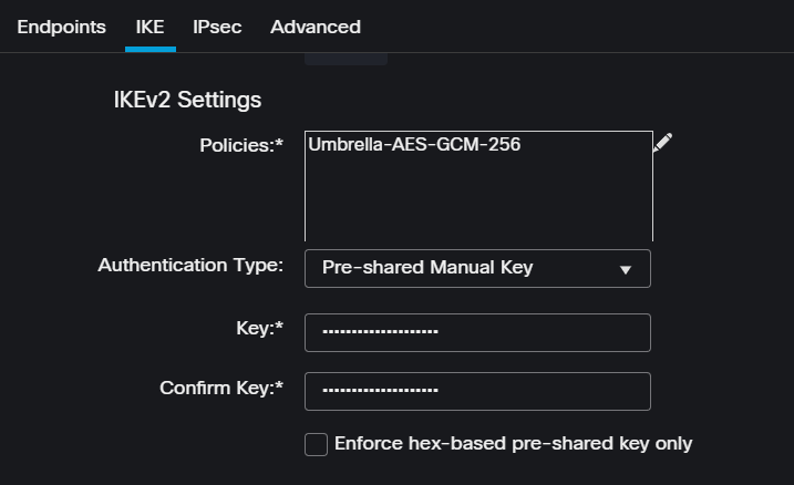
Policies: You can use the default Umbrella configurationUmbrella-AES-GCM-256or you can configure different parameters based on theSupported IKEv2 and IPSEC Parameters
Authentication Type: Pre-shared Manual KeyKeyandConfirm Key: You can find thePassphraseinformation in the step: Data for Tunnel Setup
After that, your configuration for IKE is completed, and you can now go to the step, IPSEC Configuration.
IPSEC Configuration
To configure the IPSEC parameters, click on IPSEC.

Under IPSEC, you must configure the next parameters:
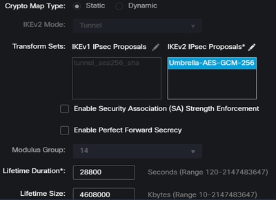
Policies: You can use the default Umbrella configurationUmbrella-AES-GCM-256or you can configure a different parameters based on theSupported IKEv2 and IPSEC Parameters
Note: Nothing else is required on IPSEC.
Now your configuration for IPSEC is completed.
Advanced Configuration
To configure the advanced parameters, click on Advanced.

Under Advanced, you must configure the next parameters:
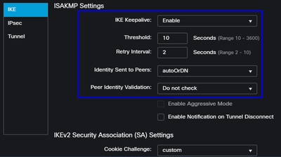
IKE Keepalive: EnableThreshold: 10Retry Interval: 2Identity Sent to Peers: autoOrDNPeer Identity Validation: Do not Check
Click on Save and Deploy.
Note: After a few minutes, the VPN is established for both nodes.
The configuration for the VPN to Secure Access in VTI Mode is completed, and you can go to step, Configure Policy Base Routing.

Warning: Traffic to Secure Access is forwarded only to the primary Tunnel when both tunnels are established; if the primary gets down, Secure Access allow the traffic to be forwarded through the secondary Tunnel.
Note: The failover on the Secure Access site is based on the DPD values documented on the user guide for Supported IPsec values.
Access Policy Configuration Scenarios
The access policy rules defined are based on:

| Interface |
Zone |
| PrimaryVTI |
SIG |
| SecondaryVTI |
SIG |
| LAN |
LAN |
Internet Access Scenario
To provide access to the Internet on all the resources you configure on the Policy Base Routing. You must configure some access rules and some policies in secure access.
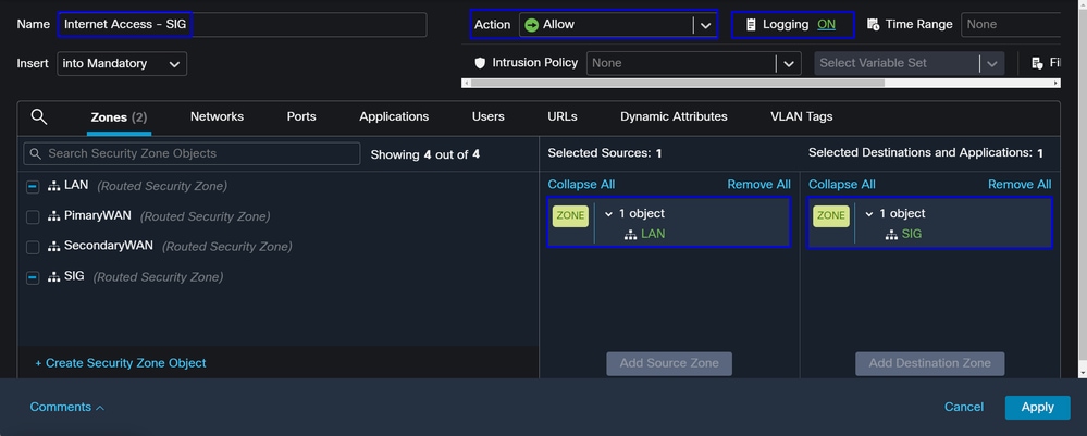
This rule provide access to the LAN on the Internet, and in this case, the Internet is SIG.
RA-VPN Escenario
To provide access from the RA-VPN users, you must configure it based on the range you assigned on the RA-VPN Pool.
Note: To configure your RA-VPNaaS policy, you can go through Manage Virtual Private Networks.
How do you verify the IP pool of your VPNaaS?
Navigate to your Secure Access Dashboard
- Click on
Connect>End User Connectivity - Click on
Virtual Private Network - Under
Manage IP Pools, then click onManage
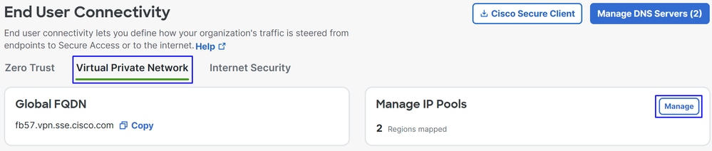
- You can see your pool under
Endpoint IP Pools.
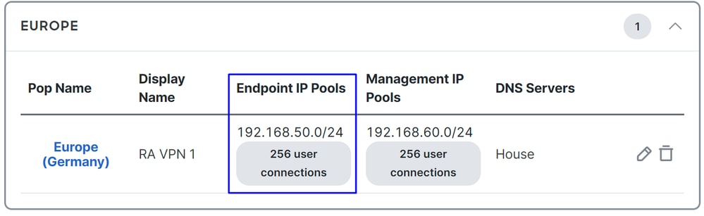
- You must permit this range under SIG, however, you must also add it under the ACL that you configured in your PBR.
Access Rule Configuration
If you are only configuring Secure Access to use it with the capabilities to access the private applications resources, your access rule can look like this:
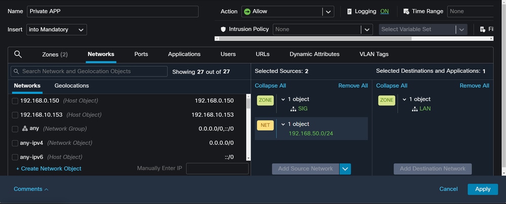
That rule permits traffic from the RA-VPN Pool 192.168.50.0/24 to your LAN; you can specify more if needed.
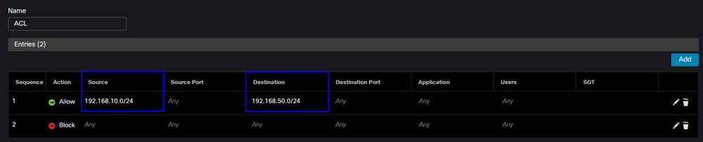
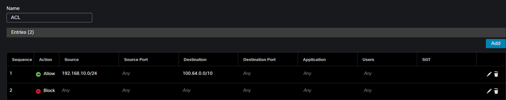
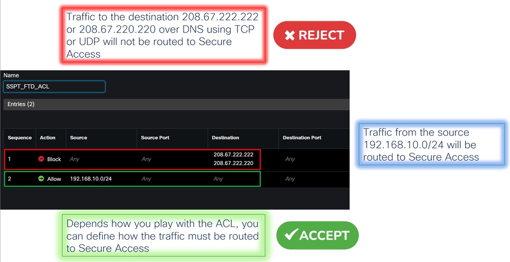
ACL Configuration
To permit the routing traffic from SIG to your LAN, you must add it under the ACL to make it work under the PBR.
CLAP-BAP ZTNA Escenario
You must configure your network based on the CGNAT range 100.64.0.0/10 to provide access to your network from the Client Base ZTA or Browser Base ZTA users.
Access Rule Configuration
If you are only configuring Secure Access to use it with the capabilities to access the private applications resources, your access rule can look like this:

This rule permits traffic from the ZTNA CGNAT Range 100.64.0.0/10 to your LAN.
ACL Configuration
To permit routing traffic from SIG using CGNAT to your LAN, you must add it under the ACL to make it work under the PBR.
Configure Policy Base Routing
To provide access to internal resources and the Internet through Secure Access, you must create routes via Policy Base Routing (PBR) that facilitate routing the traffic from the source to the destination.
- Navigate to
Devices > Device Management - Choose the FTD device where you create the route
- Click on
Routing - Choose
Policy Base Routing ClickAdd

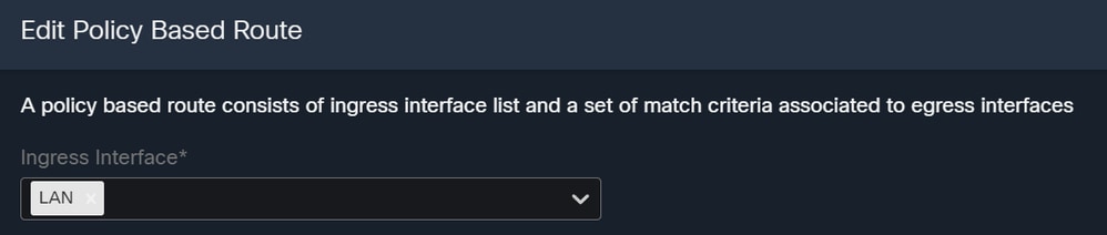
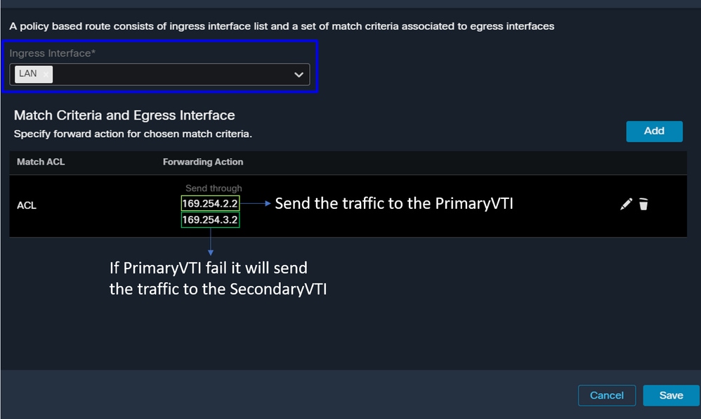
In this scenario, you select all interfaces you use as a source to route traffic to Secure Access or to provide user authentication to Secure Access using RA-VPN. client-based, or browser-based ZTA access to the Network internal resources:
- Under Ingress Interface, select all interfaces that send traffic through Secure Access:
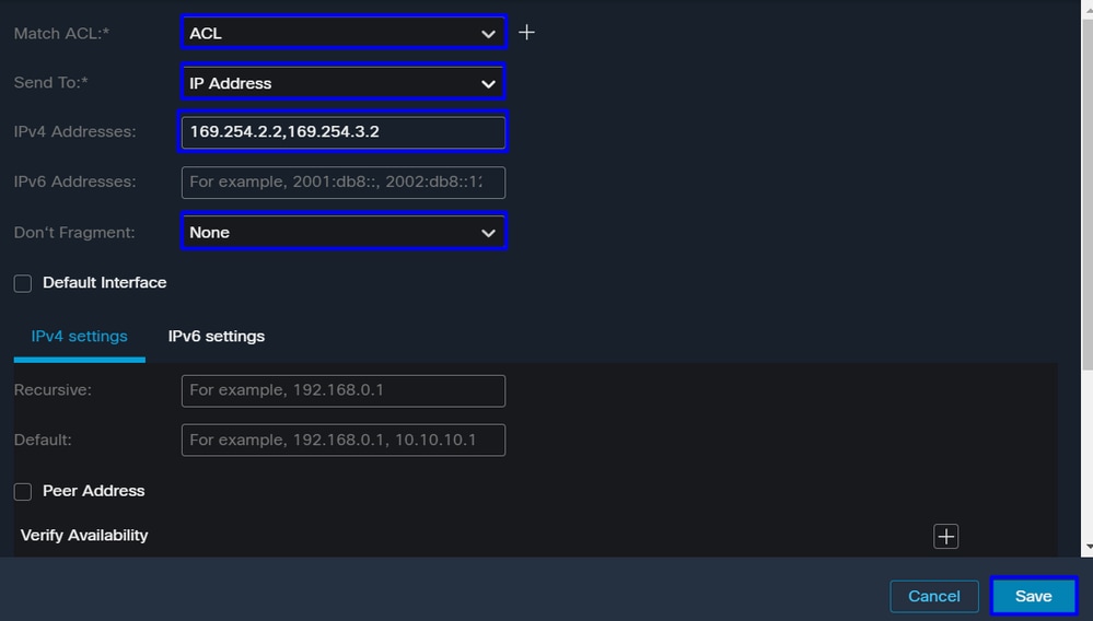
- Under Match Criteria and Egress Interface, you define the next parameters after you click
Add:

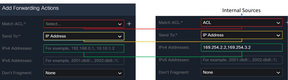
Match ACL: For this ACL, configure everything you route to Secure Access:
Send To: Choose the IP AddressIPv4 Addresses: You must use the next IP under the mask 30 that was configured on both VTIs; you can check that under the step: VTI Interface Config
| Interface |
IP |
GW |
| PrimaryVTI |
169.254.2.1/30 |
169.254.2.2 |
| SecondaryVTI |
169.254.3.1/30 |
169.254.3.2 |

Once configured, you have the next results, click Save:
After that, you need to Save it again, and you have it configured in the next way:
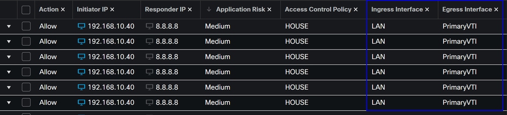
You can Deploy and you can see the traffic of the machines configured on the ACL routing the traffic to Secure Access:
From the Conexion Events in the FMC:
From the Activity Search in Secure Access:
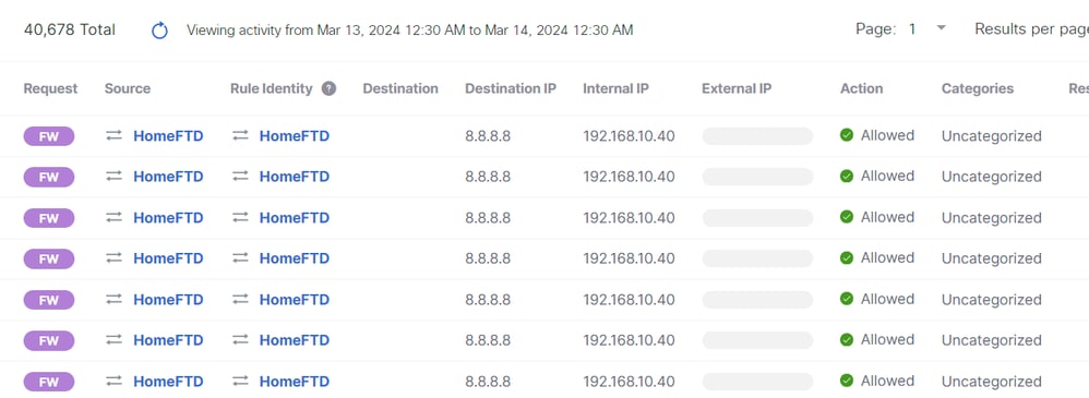
Note: By default, the Secure Access Policy allows traffic to the Internet. To provide access to private applications, you must create private resources and add them to the access policy for private resource access.
Configure Internet Access Policy on Secure Access
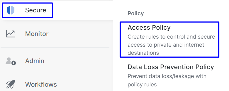
To configure Internet access, you must create the policy on your Secure Access Dashboard:
- Click on
Secure > Access Policy
- Click on
Add Rule>Internet Access
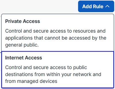
There, you can specify the source as the tunnel, and to the destination. You can choose any, depending on what you're configuring on the policy. Please review the Secure Access User Guide.
Configure Private Resource Access for ZTNA and RA-VPN
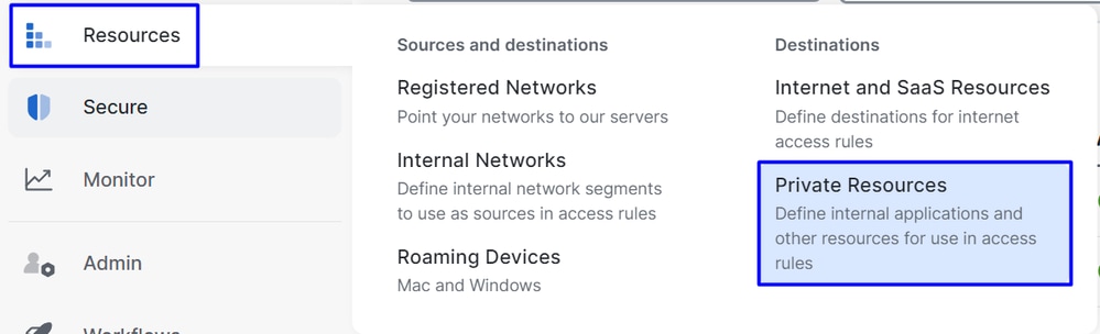
To configure access for private resources, you must create the resources first under the Secure Access Dashboard:
- Click on
Resources > Private Resources
- Then click
Add Under the configuration, you can find the next sections to configure:General, Communication with Secure Access Cloud and Endpoint Connection Methods.
General
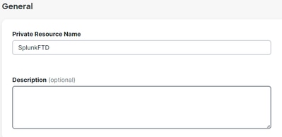
Private Resource Name: Create a name for the resource you are providing access through Secure Access to your network.
Endpoint Connection Methods
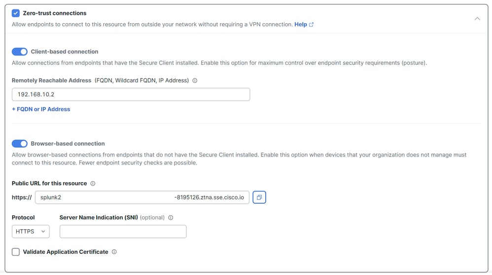
Zero Trust Connections: Mark the checkbox.Client-based connection: If you enable this, you can use the Secure Client - Zero Trust Module to enable access through client-base mode.Remote Reachable Address (FQDN, Wildcard FQDN, IP Address): Configure the resources IP or FQDN. if you configure FQDN, you must add DNS to resolve the name.Browser-based connection: If you enable this, you can access your resources via browser (please only add resources with HTTP or HTTPS communication).Public URL for this resource: Configure the public URL you use through your browser (Secure Access protects this resource).Protocol: Select the protocol (HTTP or HTTPS).

VPN Connection: Mark the checkbox to enable access via RA-VPNaaS.
Click Save and you can add that resource to the Access Policy.
Configure the Access Policy
When you create the resource, you must assign it to one of the Secure Access Policies:
- Click on
Secure > Access Policy

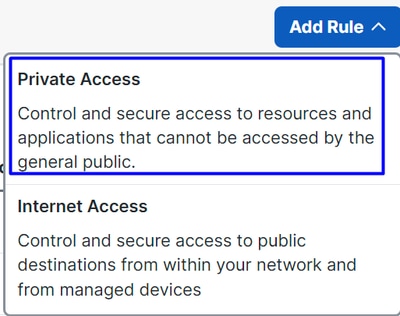
- Click
Add > Private Resource
For this Private Access rule, you must configure the default values to provide access to the resource. For more information about policy configurations, review the User Guide.
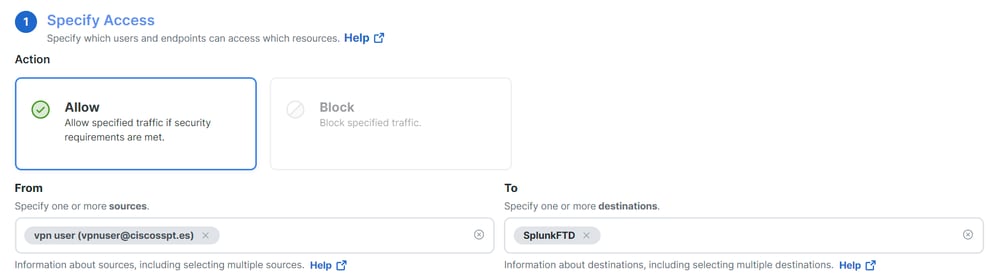
Action: Choose Allow to provide access to the resource.From: Specify the user that can be used to log in to the resource.To: Choose the resource that you want to access through Secure Access.

Zero-Trust Client-based Posture Profile: Choose the default profile for client base accessZero-Trust Browser-based Posture Profile: Choose the default profile for browser base access
Note: For more information about the posture policy, please review the user guide on Secure Access.
- Click
NextandSaveafter your configurations, and you can access your resources through RA-VPN, Client Base ZTNA, or Browser Base ZTNA.
Troubleshoot
To troubleshoot between Secure Firewall and Secure Access, you can verify if Phase1 (IKEv2) and Phase2 (IPSEC) are established between devices.
Verify Phase1 (IKEv2)
To verify Phase1, you must run the next command on the CLI of your FTD:
show crypto isakmp saIn this case, the desired output is two IKEv2 SAs established to the Data Center IPs of Secure Access and the desired status as READY:
There are no IKEv1 SAs

IKEv2 SAs:

Session-id:3, Status:UP-ACTIVE, IKE count:1, CHILD count:1

Tunnel-id Local                                               Remote                                     fvrf/ivrf     Status         Role
 52346451 192.168.0.202/4500                                  3.120.45.23/4500                        Global/Global      READY    RESPONDER
      Encr: AES-GCM, keysize: 256, Hash: N/A, DH Grp:20, Auth sign: PSK, Auth verify: PSK
      Life/Active Time: 86400/4009 sec
Child sa: local selector  0.0.0.0/0 - 255.255.255.255/65535
          remote selector 0.0.0.0/0 - 255.255.255.255/65535
          ESP spi in/out: 0xfb34754c/0xc27fd2ba

IKEv2 SAs:

Session-id:2, Status:UP-ACTIVE, IKE count:1, CHILD count:1

Tunnel-id Local                                               Remote                                     fvrf/ivrf     Status         Role
 52442403 192.168.30.5/4500                                   18.156.145.74/4500                      Global/Global      READY    RESPONDER
      Encr: AES-GCM, keysize: 256, Hash: N/A, DH Grp:20, Auth sign: PSK, Auth verify: PSK
      Life/Active Time: 86400/3891 sec
Child sa: local selector  0.0.0.0/0 - 255.255.255.255/65535
          remote selector 0.0.0.0/0 - 255.255.255.255/65535
          ESP spi in/out: 0x4af761fd/0xfbca3343
Verify Phase2 (IPSEC)
To verify Phase2, you must run the next command on the CLI of your FTD:
interface: PrimaryVTI
    Crypto map tag: __vti-crypto-map-Tunnel1-0-1, seq num: 65280, local addr: 192.168.30.5

      Protected vrf (ivrf): Global
      local ident (addr/mask/prot/port): (0.0.0.0/0.0.0.0/0/0)
      remote ident (addr/mask/prot/port): (0.0.0.0/0.0.0.0/0/0)
      current_peer: 18.156.145.74


      #pkts encaps: 71965, #pkts encrypt: 71965, #pkts digest: 71965
      #pkts decaps: 91325, #pkts decrypt: 91325, #pkts verify: 91325
      #pkts compressed: 0, #pkts decompressed: 0
      #pkts not compressed: 71965, #pkts comp failed: 0, #pkts decomp failed: 0
      #pre-frag successes: 0, #pre-frag failures: 0, #fragments created: 0
      #PMTUs sent: 0, #PMTUs rcvd: 0, #decapsulated frgs needing reassembly: 0
      #TFC rcvd: 0, #TFC sent: 0
      #Valid ICMP Errors rcvd: 0, #Invalid ICMP Errors rcvd: 0
      #send errors: 0, #recv errors: 0

      local crypto endpt.: 192.168.30.5/4500, remote crypto endpt.: 18.156.145.74/4500
      path mtu 1500, ipsec overhead 63(44), media mtu 1500
      PMTU time remaining (sec): 0, DF policy: copy-df
      ICMP error validation: disabled, TFC packets: disabled
      current outbound spi: FBCA3343
      current inbound spi : 4AF761FD

    inbound esp sas:
      spi: 0x4AF761FD (1257726461)
         SA State: active
         transform: esp-aes-gcm-256 esp-null-hmac no compression
         in use settings ={L2L, Tunnel,  NAT-T-Encaps, IKEv2, VTI, }
         slot: 0, conn_id: 2, crypto-map: __vti-crypto-map-Tunnel1-0-1
         sa timing: remaining key lifetime (kB/sec): (3916242/27571)
         IV size: 8 bytes
         replay detection support: Y
         Anti replay bitmap:
          0xFFFFFFFF 0xFFFFFFFF
    outbound esp sas:
      spi: 0xFBCA3343 (4224332611)
         SA State: active
         transform: esp-aes-gcm-256 esp-null-hmac no compression
         in use settings ={L2L, Tunnel,  NAT-T-Encaps, IKEv2, VTI, }
         slot: 0, conn_id: 2, crypto-map: __vti-crypto-map-Tunnel1-0-1
         sa timing: remaining key lifetime (kB/sec): (4239174/27571)
         IV size: 8 bytes
         replay detection support: Y
         Anti replay bitmap:
          0x00000000 0x00000001

interface: SecondaryVTI
    Crypto map tag: __vti-crypto-map-Tunnel2-0-2, seq num: 65280, local addr: 192.168.0.202

      Protected vrf (ivrf): Global
      local ident (addr/mask/prot/port): (0.0.0.0/0.0.0.0/0/0)
      remote ident (addr/mask/prot/port): (0.0.0.0/0.0.0.0/0/0)
      current_peer: 3.120.45.23


      #pkts encaps: 0, #pkts encrypt: 0, #pkts digest: 0
      #pkts decaps: 0, #pkts decrypt: 0, #pkts verify: 0
      #pkts compressed: 0, #pkts decompressed: 0
      #pkts not compressed: 0, #pkts comp failed: 0, #pkts decomp failed: 0
      #pre-frag successes: 0, #pre-frag failures: 0, #fragments created: 0
      #PMTUs sent: 0, #PMTUs rcvd: 0, #decapsulated frgs needing reassembly: 0
      #TFC rcvd: 0, #TFC sent: 0
      #Valid ICMP Errors rcvd: 0, #Invalid ICMP Errors rcvd: 0
      #send errors: 0, #recv errors: 0

      local crypto endpt.: 192.168.0.202/4500, remote crypto endpt.: 3.120.45.23/4500
      path mtu 1500, ipsec overhead 63(44), media mtu 1500
      PMTU time remaining (sec): 0, DF policy: copy-df
      ICMP error validation: disabled, TFC packets: disabled
      current outbound spi: C27FD2BA
      current inbound spi : FB34754C

    inbound esp sas:
      spi: 0xFB34754C (4214519116)
         SA State: active
         transform: esp-aes-gcm-256 esp-null-hmac no compression
         in use settings ={L2L, Tunnel,  NAT-T-Encaps, IKEv2, VTI, }
         slot: 0, conn_id: 20, crypto-map: __vti-crypto-map-Tunnel2-0-2
         sa timing: remaining key lifetime (kB/sec): (4101120/27412)
         IV size: 8 bytes
         replay detection support: Y
         Anti replay bitmap:
          0x00000000 0x00000001
    outbound esp sas:
      spi: 0xC27FD2BA (3263156922)
         SA State: active
         transform: esp-aes-gcm-256 esp-null-hmac no compression
         in use settings ={L2L, Tunnel,  NAT-T-Encaps, IKEv2, VTI, }
         slot: 0, conn_id: 20, crypto-map: __vti-crypto-map-Tunnel2-0-2
         sa timing: remaining key lifetime (kB/sec): (4239360/27412)
         IV size: 8 bytes
         replay detection support: Y
         Anti replay bitmap:
          0x00000000 0x00000001
In the last output, you can see both tunnels established; what is not desired is the next output under the packet encaps and decaps.
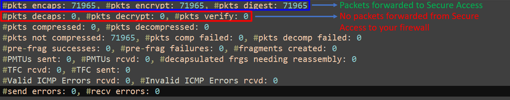
If you have this scenario, open a case with TAC.
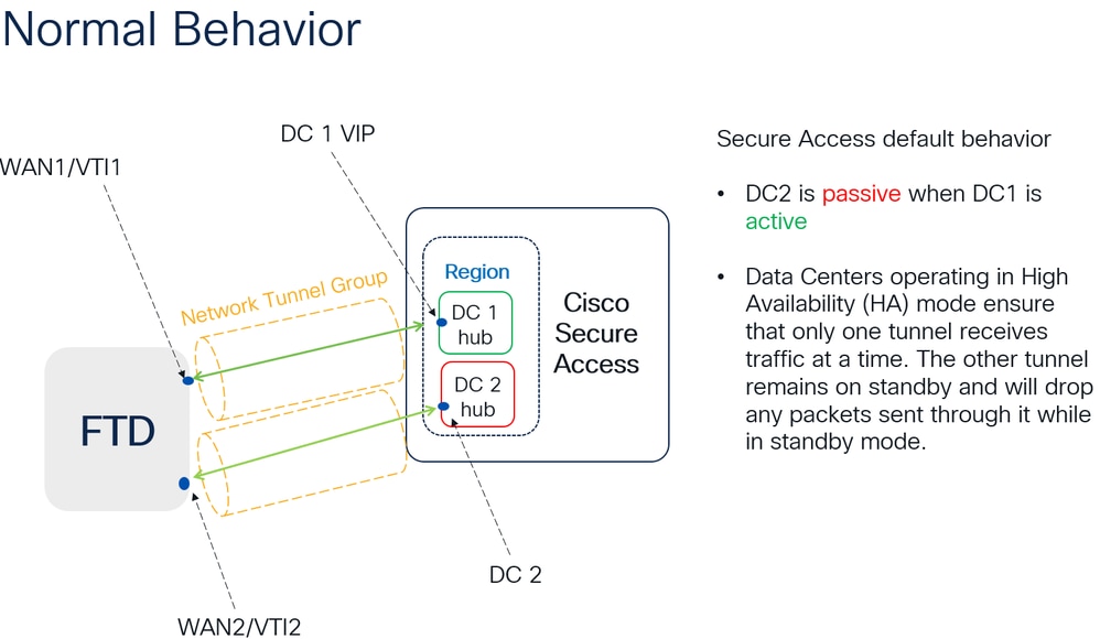
High Availability Function
The function of the tunnels with Secure Access communicating with the data center in the cloud Is active/passive, which means only the door for DC 1 is open to receive traffic; the door for DC 2 is closed until tunnel number 1 is down.

Verify Traffic Routing to Secure Access
In this example, the source machine on the firewall network used is:
- Source: 192.168.10.40
- Destination: 146.112.255.40 (Secure Access Monitoring IP)
Example:
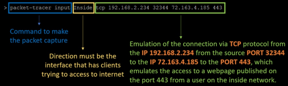
Command:
packet-tracer input LAN tcp 192.168.10.40 3422 146.112.255.40 80Output:
Phase: 1
Type: ACCESS-LIST
Subtype:
Result: ALLOW
Elapsed time: 14010 ns
Config:
Implicit Rule
Additional Information:
MAC Access list

Phase: 2
Type: PBR-LOOKUP
Subtype: policy-route
Result: ALLOW
Elapsed time: 21482 ns
Config:
route-map FMC_GENERATED_PBR_1707686032813 permit 5
 match ip address ACL
 set ip next-hop 169.254.2.2 169.254.3.2
Additional Information:
 Matched route-map FMC_GENERATED_PBR_1707686032813, sequence 5, permit
 Found next-hop 169.254.2.2 using egress ifc PrimaryVTI

Phase: 3
Type: OBJECT_GROUP_SEARCH
Subtype:
Result: ALLOW
Elapsed time: 0 ns
Config:
Additional Information:
 Source Object Group Match Count:       0
 Destination Object Group Match Count:  0
 Object Group Search:                   0

Phase: 4
Type: ACCESS-LIST
Subtype: log
Result: ALLOW
Elapsed time: 233 ns
Config:
access-group CSM_FW_ACL_ global
access-list CSM_FW_ACL_ advanced permit ip any ifc PrimaryVTI any rule-id 268434435
access-list CSM_FW_ACL_ remark rule-id 268434435: ACCESS POLICY: HOUSE - Mandatory
access-list CSM_FW_ACL_ remark rule-id 268434435: L7 RULE: New-Rule-#3-ALLOW
Additional Information:
 This packet will be sent to snort for additional processing where a verdict will be reached

Phase: 5
Type: CONN-SETTINGS
Subtype:
Result: ALLOW
Elapsed time: 233 ns
Config:
class-map class_map_Any
 match access-list Any
policy-map policy_map_LAN
 class class_map_Any
  set connection decrement-ttl
service-policy policy_map_LAN interface LAN
Additional Information:

Phase: 6
Type: NAT
Subtype: per-session
Result: ALLOW
Elapsed time: 233 ns
Config:
Additional Information:

Phase: 7
Type: IP-OPTIONS
Subtype:
Result: ALLOW
Elapsed time: 233 ns
Config:
Additional Information:

Phase: 8
Type: VPN
Subtype: encrypt
Result: ALLOW
Elapsed time: 18680 ns
Config:
Additional Information:

Phase: 9
Type: VPN
Subtype: ipsec-tunnel-flow
Result: ALLOW
Elapsed time: 25218 ns
Config:
Additional Information:

Phase: 10
Type: NAT
Subtype: per-session
Result: ALLOW
Elapsed time: 14944 ns
Config:
Additional Information:

Phase: 11
Type: IP-OPTIONS
Subtype:
Result: ALLOW
Elapsed time: 0 ns
Config:
Additional Information:

Phase: 12
Type: FLOW-CREATION
Subtype:
Result: ALLOW
Elapsed time: 19614 ns
Config:
Additional Information:
New flow created with id 23811, packet dispatched to next module

Phase: 13
Type: EXTERNAL-INSPECT
Subtype:
Result: ALLOW
Elapsed time: 27086 ns
Config:
Additional Information:
Application: 'SNORT Inspect'

Phase: 14
Type: SNORT
Subtype: appid
Result: ALLOW
Elapsed time: 28820 ns
Config:
Additional Information:
service: (0), client: (0), payload: (0), misc: (0)

Phase: 15
Type: SNORT
Subtype: firewall
Result: ALLOW
Elapsed time: 450193 ns
Config:
Network 0, Inspection 0, Detection 0, Rule ID 268434435
Additional Information:
Starting rule matching, zone 1 -> 3, geo 0 -> 0, vlan 0, src sgt: 0, src sgt type: unknown, dst sgt: 0, dst sgt type: unknown, user 9999997, no url or host, no xff
Matched rule ids 268434435 - Allow

Result:
input-interface: LAN(vrfid:0)
input-status: up
input-line-status: up
output-interface: PrimaryVTI(vrfid:0)
output-status: up
output-line-status: up
Action: allow
Time Taken: 620979 ns
There are many scenarios that can provide additional context on the set up under the PBR configuration to ensure traffic is routed correctly to Secure Access:
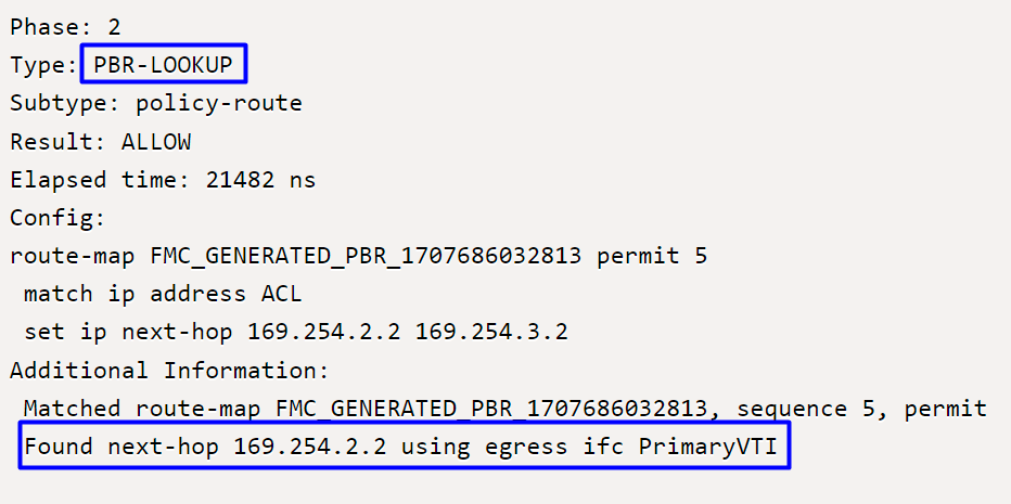
Phase 2 indicates that traffic is forwarded to the PrimaryVTI interface, which is correct based on the configurations in this scenario as the Internet traffic must be forwarded to Secure Access through the VTI.
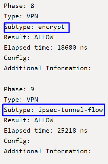
Phase 8 corresponds to the encryption stage in a VPN connection, where traffic is evaluated and authorized for encryption, ensuring data is securely transmitted. Phase 9 focuses on the specific management of the traffic flow within the VPN IPSec tunnel, confirming encrypted traffic is properly routed and allowed through the established tunnel.
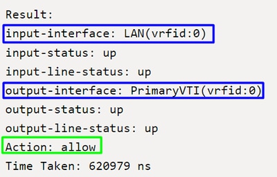
To finalize, at the end of the flow, you can see the traffic from the LAN to the PrimaryVTI forwarding traffic to Secure Access. This action confirms that traffic is routed without issue.
Related Information
- Cisco Technical Support & Downloads
- Cisco Secure Access Help Center
- Virtual Trusted Platform Module Overview
- Zero Trust Access Module
- Troubleshoot Secure Access Error "Enrollment Service Is Not Responding. Contact Your IT Help Desk"
Revision History
| Revision | Publish Date | Comments |
|---|---|---|
2.0 |
02-Jun-2026
|
Updated spelling, grammar, spacing, alt text, etc. |
1.0 |
28-Nov-2024
|
Initial Release |
 Feedback
Contact Cisco
- Open a Support Case

- (Requires a Cisco Service Contract)