Configure Secure Access IOS XE Tunnel via BGP and ECMP
Available Languages
Contents
Introduction
This document describes steps required to configure and troubleshoot IPSec VPN tunnel between Cisco Secure Access and Cisco IOS XE using BGP and ECMP.
Network Diagram
In this lab example, this scenario shows network 192.168.150.0/24 has LAN segment behind the Cisco IOS XE device, and 192.168.200.0/24 has IP pool used by RAVPN with users connecting to Secure Access headend.
The end goal is to utilize ECMP on VPN tunnels between the Cisco IOS XE device and Secure Access headend. To better understand the topology, refer to the diagram:


Note: This is an example packet flow you can apply the same principles to any other flow(s), and to Secure Internet Access from 192.168.150.0/24 subnet behind Cisco IOS XE router.
Prerequisites
Requirements
You must have knowledge of these topics:
- Cisco IOS XE CLI configuration and management
- Basic knowledge of IKEv2 and IPSec protocols
- Initial Cisco IOS XE Configuration (IP Addressing, SSH, License)
- Basic knowledge of BGP and ECMP
Components Used
This document is based on these software and hardware versions:
- C8000V running 17.9.4a software version
- Windows PC
- Cisco Secure Access Organization
The information in this document was created from the devices in a specific lab environment. All of the devices used in this document started with a cleared (default) configuration. If your network is live, ensure that you understand the potential impact of any command.
Background Information
Network Tunnels in Secure Access have a bandwidth limitation of 1 Gbps per single tunnel. If your upstream/downstream internet bandwidth is higher than 1 Gbps and you want to utilize it fully, you must configure multiple tunnels using the same Secure Access Data Center by grouping them in a single ECMP group.
When you terminate multiple tunnels with a single Network Tunnel Group (within a single Secure Access DC), by default they form a ECMP group from the Secure Access headend perspective. Once Secure Access headend sends traffic towards the on-premises VPN device, it load balances between the tunnels (assuming correct routes are received from BGP peers).
To achieve the same functionality with the on-premises VPN device, you must configure multiple VTI interfaces on a single router, and ensure proper routing configurations are applied. This article covers those scenarios with an explanation of each step.
Configure
Secure Access Configuration
There is are special configurations that must be applied on the Secure Access side to form an ECMP group from multiple VPN tunnels using the BGP protocol.
Configure the Network Tunnel Group:
- Create a new Network Tunnel Group (or edit existing one):

- Specify the Tunnel ID and passphrase:

- Configure the Routing options, specify the Dynamic Routing, and enter your internal AS number. In this lab scenario, the ASN is equal to 65000:
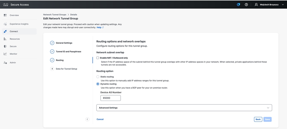
- Note the tunnel details from the Data for Tunnel Setup section.
Cisco IOS XE Configuration
This section covers CLI configuration that must be applied on the Cisco IOS XE router. To properly configure the IKEv2 tunnels, BGP neighborship, and ECMP load balancing across Virtual Tunnel Interfaces.
Each section is explained and most common caveats are mentioned.
IKEv2 and IPsec Parameters
Configure the IKEv2 Policy and IKEv2 Proposal, these parameters define which algorithms are used for IKE SA (Phase 1):
crypto ikev2 proposal sse-proposal
encryption aes-gcm-256
prf sha256
group 19 20

crypto ikev2 policy sse-pol
proposal sse-proposal
Note: Refer to the suggested and optimal parameters marked in bold in the Supported IPsec Parameters SSE Guide.
Define IKEv2 keyring that explains headend IP address and the pre-shared key used to authenticate with the SSE headend:
crypto ikev2 keyring sse-keyring
 peer sse
 address 35.179.86.116
 pre-shared-key local <boring_generated_password>
 pre-shared-key remote <boring_generated_password>
Configure Pair of IKEv2 Profiles
This defines the type of IKE identity to use, which matches the remote peer, and which IKE identity local router is sending to the peer. The IKE identity of the SSE headend is of IP address type and is equal to the Public IP of the SSE headend.

Warning: To establish multiple tunnels with the same Network Tunnel Group on the SSE side, they all must use the same local IKE identity. Cisco IOS XE does not support such scenarios, as it requires a unique pair of local and remote IKE identities per tunnel. To overcome this limitation, the SSE headend was enhanced to accept the IKE ID in the format of: <tunneld_id>+<suffix>@<org><hub>.sse.cisco.com
As discussed in the lab scenario, the tunnel ID was defined as: cat8k-dmz. In a normal scenario, you would configure the router to send the local IKE identity as: cat8k-dmz@8195165-622405748-sse.cisco.com.
However, to establish multiple tunnels with the same Network Tunnel Group, the local IKE IDs to be used: cat8k-dmz+tunnel1@8195165-622405748-sse.cisco.com and cat8k-dmz+tunnel2@8195165-622405748-sse.cisco.com.
The suffix added to each string: (tunnel1 and tunnel2).
Note: As mentioned previously, local IKE identities are examples used in this lab scenario. You can define any suffix you like, just ensure to meet the requirements.
crypto ikev2 profile sse-ikev2-profile-tunnel1
 match identity remote address 35.179.86.116 255.255.255.255
 identity local email cat8k-dmz+tunnel1@8195165-622405748-sse.cisco.com
 authentication remote pre-share
 authentication local pre-share
 keyring local sse-keyring
 dpd 10 2 periodic

crypto ikev2 profile sse-ikev2-profile-tunnel2
 match identity remote address 35.179.86.116 255.255.255.255
 identity local email cat8k-dmz+tunnel2@8195165-622405748-sse.cisco.com
 authentication remote pre-share
 authentication local pre-share
 keyring local sse-keyring
 dpd 10 2 periodic
Configure the IPSec transform set. This setting defines algorithms used for the IPsec Security Association (Phase 2):
crypto ipsec transform-set sse-transform esp-gcm 256
mode tunnel
Configure IPSec profiles that link IKEv2 profiles with Transform Sets:
crypto ipsec profile sse-ipsec-profile-1
set transform-set sse-transform
set ikev2-profile sse-ikev2-profile-tunnel1

crypto ipsec profile sse-ipsec-profile-2
set transform-set sse-transform
set ikev2-profile sse-ikev2-profile-tunnel2
Virtual Tunnel Interfaces
This section covers configurations of Virtual Tunnel Interfaces and Loopback interfaces used as tunnel sources. In the previously discussed lab scenario, you must establish two VTI interfaces with a single peer using the same public IP address. Also, the Cisco IOS XE device has only one egress interface GigabitEthernet1. The Cisco IOS XE does not support configurations of more than one VTI with the same tunnel source and tunnel destination.
To overcome this limitation, you can use the Loopback interfaces and define them as a tunnel source in the respective VTI.
There are a few options to achieve IP connectivity between Loopback and an SSE Public IP Address:
- Assign a publicly routable IP address to a Loopback interface (requires ownership of a public IP address space).
- Assign a private IP address to a Loopback interface and dynamically NAT traffic with a Loopback IP source.
- Use the VASI interface (not supported on many platforms, cumbersome to setup and troubleshoot).
In this scenario, the next steps discussed detail the second option.
Configure two Loopback interfaces and add the "ip nat inside" command under each.
interface Loopback1
ip address 10.1.1.38 255.255.255.255
ip nat inside
end

interface Loopback2
ip address 10.1.1.70 255.255.255.255
ip nat inside
end
Define the dynamic NAT Access-Control List and the NAT overload statement:
ip access-list extended NAT
10 permit ip 10.1.1.0 0.0.0.255 any

ip nat inside source list NAT interface GigabitEthernet1 overload
Configure the Virtual Tunnel Interfaces:
interface Tunnel1
ip address 169.254.0.10 255.255.255.252
tunnel source Loopback1
tunnel mode ipsec ipv4
tunnel destination 35.179.86.116
tunnel protection ipsec profile sse-ipsec-profile-1
end

!
interface Tunnel2
ip address 169.254.0.14 255.255.255.252
tunnel source Loopback2
tunnel mode ipsec ipv4
tunnel destination 35.179.86.116
tunnel protection ipsec profile sse-ipsec-profile-2
end
Note: As described in the lab scenario, the IP addresses assigned to VTIs are from non-overlapping subnets of 169.254.0.0/24. You can use other subnet spaces, however, there are certain requirements related to BGP, which requires address space.
BGP Routing
This section covers configuration steps that are required to establish BGP neighborship with SSE headend. The BGP process on the SSE headend listens on any IP from subnet 169.254.0.0/24. To establish BGP peering over both VTIs, there are two neighbors to define" 169.254.0.9 (Tunnel1) and 169.254.0.13 (Tunnel2). Also, you must specify the Remote AS value seen in the SSE dashboard.
Starting November 2025, all newly created Secure Access organizations must use the Public ASN 32644 by default for BGP peering in network tunnel groups. Existing organizations established prior to November 2025 can continue to use the Private ASN 64512 that was previously reserved for Secure Access BGP peers.
router bgp 65000
bgp log-neighbor-changes
neighbor 169.254.0.9 remote-as 32644
neighbor 169.254.0.9 ebgp-multihop 255
neighbor 169.254.0.13 remote-as 32644
neighbor 169.254.0.13 ebgp-multihop 255
!
address-family ipv4
network 192.168.150.0
neighbor 169.254.0.9 activate
neighbor 169.254.0.13 activate
maximum-paths 2
Note: Routes received from both peers must be exactly the same. By default, router installs only one in the routing table. To allow more than one duplicate route to be installed in the routing table (and enable ECMP), you must configure "maximum-paths <numer of routes>".
Verify
Secure Access Dashboard
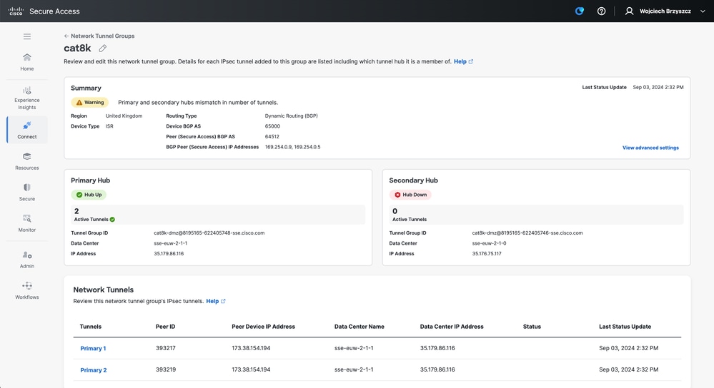
You must see two Primary tunnels in the SSE dashboard:
Cisco IOS XE Router
Verify both tunnels are in READY state from the Cisco IOS XE side:
wbrzyszc-cat8k#show crypto ikev2 sa
IPv4 Crypto IKEv2 SA

Tunnel-id Local          Remote             fvrf/ivrf Status
1         10.1.1.70/4500 35.179.86.116/4500 none/none READY
    Encr: AES-GCM, keysize: 256, PRF: SHA256, Hash: None, DH Grp:20, Auth sign: PSK, Auth verify: PSK
    Life/Active Time: 86400/255 sec
    CE id: 0, Session-id: 6097
    Local spi: A15E8ACF919656C5 Remote spi: 644CFD102AAF270A

Tunnel-id Local          Remote             fvrf/ivrf Status
6         10.1.1.38/4500 35.179.86.116/4500 none/none READY
    Encr: AES-GCM, keysize: 256, PRF: SHA256, Hash: None, DH Grp:20, Auth sign: PSK, Auth verify: PSK
    Life/Active Time: 86400/11203 sec
    CE id: 0, Session-id: 6096
    Local spi: E18CBEE82674E780 Remote spi: 39239A7D09D5B972
Verify the BGP neighborship is UP with both peers:
wbrzyszc-cat8k#show ip bgp summary
Neighbor V AS MsgRcvd MsgSent TblVer InQ OutQ Up/Down State/PfxRcd
169.254.0.9 4 32644 17281 18846 160 0 0 5d23h 15
169.254.0.13 4 32644 17281 18845 160 0 0 5d23h 15
Verify the router learns proper routes from BGP (and there are at least two next hops installed in routing table):
wbrzyszc-cat8k#show ip route 192.168.200.0
Routing entry for 192.168.200.0/25, 2 known subnets
B 192.168.200.0 [20/0] via 169.254.0.13, 5d23h
                [20/0] via 169.254.0.9, 5d23h
B 192.168.200.128 [20/0] via 169.254.0.13, 5d23h
                  [20/0] via 169.254.0.9, 5d23h

wbrzyszc-cat8k#show ip cef 192.168.200.0
192.168.200.0/25
    nexthop 169.254.0.9 Tunnel1
    nexthop 169.254.0.13 Tunnel2
Initiate traffic and verify both tunnels are utilized and you see encaps and decaps counters increasing for both of them:
wbrzyszc-cat8k#show crypto ipsec sa | i peer|caps

current_peer 35.179.86.116 port 4500
#pkts encaps: 1881087, #pkts encrypt: 1881087, #pkts digest: 1881087
#pkts decaps: 1434171, #pkts decrypt: 1434171, #pkts verify: 1434171

current_peer 35.179.86.116 port 4500
#pkts encaps: 53602, #pkts encrypt: 53602, #pkts digest: 53602
#pkts decaps: 208986, #pkts decrypt: 208986, #pkts verify: 208986
Optionally, you can collect packet captures on both VTI interfaces to ensure traffic is load balanced between VTIs. Refer to the Configure and Capture Embedded Packet on Software Guide to configure Embedded Packet Capture on Cisco IOS XE devices. In the example, the host behind the CIsco IOS XE router with the source IP of 192.168.150.1 was sending ICMP requests to multiple IPs from 192.168.200.0/24 subnet. As you see, the ICMP requests are equally load balanced between the tunnels.
wbrzyszc-cat8k#show monitor capture Tunnel1 buffer brief
----------------------------------------------------------------------------
#   size    timestamp    source    destination    dscp   protocol
----------------------------------------------------------------------------
   0   114   0.000000    192.168.150.1   ->   192.168.200.2   0   BE    ICMP
   1   114   0.000000    192.168.150.1   ->   192.168.200.2   0   BE    ICMP
  10   114   26.564033   192.168.150.1   ->   192.168.200.5   0   BE    ICMP
  11   114   26.564033   192.168.150.1   ->   192.168.200.5   0   BE    ICMP

wbrzyszc-cat8k#show monitor capture Tunnel2 buffer brief
----------------------------------------------------------------------------
#    size    timestamp    source    destination    dscp   protocol
----------------------------------------------------------------------------
   0   114   0.000000    192.168.150.1   ->   192.168.200.1   0   BE    ICMP
   1   114   2.000000    192.168.150.1   ->   192.168.200.1   0   BE    ICMP
  10   114   38.191000   192.168.150.1   ->   192.168.200.3   0   BE    ICMP
  11   114   38.191000   192.168.150.1   ->   192.168.200.3   0   BE    ICMP
Note: There are multiple ECMP load balancing mechanisms on Cisco IOS XE routers. By default, per-destination load balancing is enabled, which ensures traffic to the same destination IP always takes the same path. You can configure per-packet load balancing, which randomly load balances traffic even for the same destination IP.
Related Information
- Secure Access User Guide
- How to Collect Embedded Packet Capture
- Technical Support & Documentation - Cisco Systems
Revision History
| Revision | Publish Date | Comments |
|---|---|---|
3.0 |
10-Jul-2026
|
Updated title, introduction, spelling, grammar, sentence structure, spacing, alt text, and CCW alerts. |
1.0 |
21-Oct-2024
|
Initial Release |

 Feedback
Contact Cisco
- Open a Support Case

- (Requires a Cisco Service Contract)